manuals.online logo
Brands
  1. Home
  2. •
  3. Brands
  4. •
  5. Toa
  6. •
  7. Handset
  8. •
  9. Toa RS-140 User manual

Toa RS-140 User manual

INSTALLATION MANUAL
3P removable terminal plug
(supplied with the Substation
interface unit)
Substation interface unit
2-core shielded cable
High-impedance speaker
(Impedance: 600 Ω or more)
Switch panel
(Figure shows the RS-140.)
Brown (A)
Red (B)
Orange (C)
Yellow (C+)
Green (B+)
Blue (A+)
Blue (COM)
Green (HOT)
N.C.Purple (H)
Brown
Red
Orange
To the substation connection terminal
1. GENERAL DESCRIPTION
The RS-140, RS-143, and RS-144 are substations to be connected to the 2-Core Shielded Substation Interface
Unit. The RS-141, designed exclusively for indoor-use in combination with the RS-140, RS-143, or RS-144, is an
option handset to make handset conversations.
For operation of the units, refer to the N-8000 series instruction manual.
Warning
This is a class A product. In a domestic environment this product may cause radio interference in which case
the user may be required to take adequate measures.
2. APPEARANCE
RS-140, RS-143, RS-144
RS-141
SWITCH PANELS
OPTION HANDSET
Note
Cut out the unused Wire (purple) to
avoid short-circuiting.
3. CONNECTIONS
3.1. Switch Panel Connections (When the Option Handset is not used)
[RS-140] [RS-143]
[RS-144]
[RS-141]
Substation interface unit
3P removable terminal plug
(supplied with the Substation
interface unit)
High-impedance speaker
(Impedance: 600 Ω or more)
Switch panel
(Figure shows the RS-140)
RS-141
N.C.
2-core shielded cable
Brown (A)
Red (B)
Orange (C)
Yellow (C+)
Green (B+)
Blue (A+)
Blue (COM)
Green (HOT)
Purple (H)
Brown (A)
Red (B)
Orange (C)
Yellow (C+)
Green (B+)
Blue (A+)
Purple (H)
Brown
Red
Orange
To the substation connection terminal
4. INSTALLATION
4.1. Switch Panel Installation
4.1.1. Dimensional diagram
[RS-140] [Mounting bracket (Supplied with the RS-140/143/144
)]
70
12.3
Unit: mm
16.3
200 or less
68.5
115
83.5
Note: The dimensions of RS-143 and RS-144 are the same as above.
Note
Cut out unused wires to avoid short-circuiting.
3.2. Switch Panel and Option Handset Connections
Note
When using the PA paging function, keep the switch panel as far away from the PA paging speaker as possible
to avoid acoustic feedback.
4.1.2. In-wall mounting using an electrical box
Mount the RS-140/143/144 to the YC-801 Flush-mount box mounted in the wall.
83.5 mm
YC-801
Flush-mount box
Wall surface
Mounting bracket
(supplied with the RS-140/143/144)
Machine screw M4 x 30
(supplied with the RS-140/143/144)
UNC No. 6-32 × 18
(supplied with the RS-140/143/144)
Switch panel
(Figure shows RS-140.)
Accessory screws
The RS-140/143/144 comes with 2 types of screws to match
the box screw threads: M4 x 30 and UNC No. 6-32 x 30.
For the electrical box provided with unified threads, use the
UNC No. 6-32 x 30.
4.1.3. On-wall mounting using a wall-mount box
Attach the RS-140/143/144 to the YC-802 Wall-mount box installed on a wall.
83.5 mm
YC-802
Wall-mount box
Wall surface
Mounting bracket
(supplied with the RS-140/143/144)
Machine screw M4 x 30
(supplied with the RS-140/143/144)
UNC No. 6-32× 18
(supplied with the RS-140/143/144)
Switch panel
(Figure shows RS-140.)
Accessory screws
The RS-140/143/144 comes with 2 types of screws to match the
box screw threads: M4 x 30 and UNC No. 6-32 x 30.
For the electrical box provided with unified threads, use the
UNC No. 6-32 x 30.
Traceability Information for Europe
Manufacturer:
TOA Corporation
7-2-1, Minatojima-Nakamachi, Chuo-ku, Kobe, Hyogo, Japan
Authorized representative:
TOA Electronics Europe GmbH
Suederstrasse 282, 20537 Hamburg, Germany
URL: http://www.toa.jp/
Model Number RS-140 RS-143 RS-144
Call Button 1 Momentary (CALL) Momentary(EMERGENCY)
Call Button 2
-
Momentary (NORMAL)
Privacy Button Latching (PRIVACY)
-
Call Indicator Flashing red
-
Conversation Indicator Lit red
-
Privacy Indicator Lit red
-
Wiring 2-core shielded cable
Transmission Distance 0.5 km/ø0.5 mm (AWG24), 800 m/ø0.65 mm (AWG22),1300 m/ø0.9 mm (AWG19)
Operating Temperature 0 to +40°C
Finish Panel Stainless steel, hairline
Call Button 1 Resin, red
Call Button 2
-
Resin, white
Privacy Button Resin, white
-
Dimensions 70 (w) x 115 (h) x 28.6 (d) mm
Weight 80 g
Accessory Mounting bracket ... 1, No. 6-32 UNC x 18 ... 2, Machine screw M4 x 30 ... 2,
No. 6-32 UNC x 30 ... 2
Applicable Box Flush-mount box: YC-801 (option)
Wall-mount box: YC-802 (option)
Model Number RS-141
Handset Receiver Dynamic type
Handset Transmitter Electret condenser type
Wiring 2-core shielded cable
Handset Receiver
Volume Control
Slide Volume
Maximum control level: 12 – 18 dB
Operating Temperature 0 to +40°C
Finish ABS resin, pale white
Dimensions 116 (w) x 220 (h) x 71 (d) mm
Weight 350 g
Accessory No. 6-32 UNC x 18 ... 4, Machine screw M4 x 25 ... 4
Applicable Box 2-gang electrical box: YC-302 (option)
5. SPECIFICATIONS
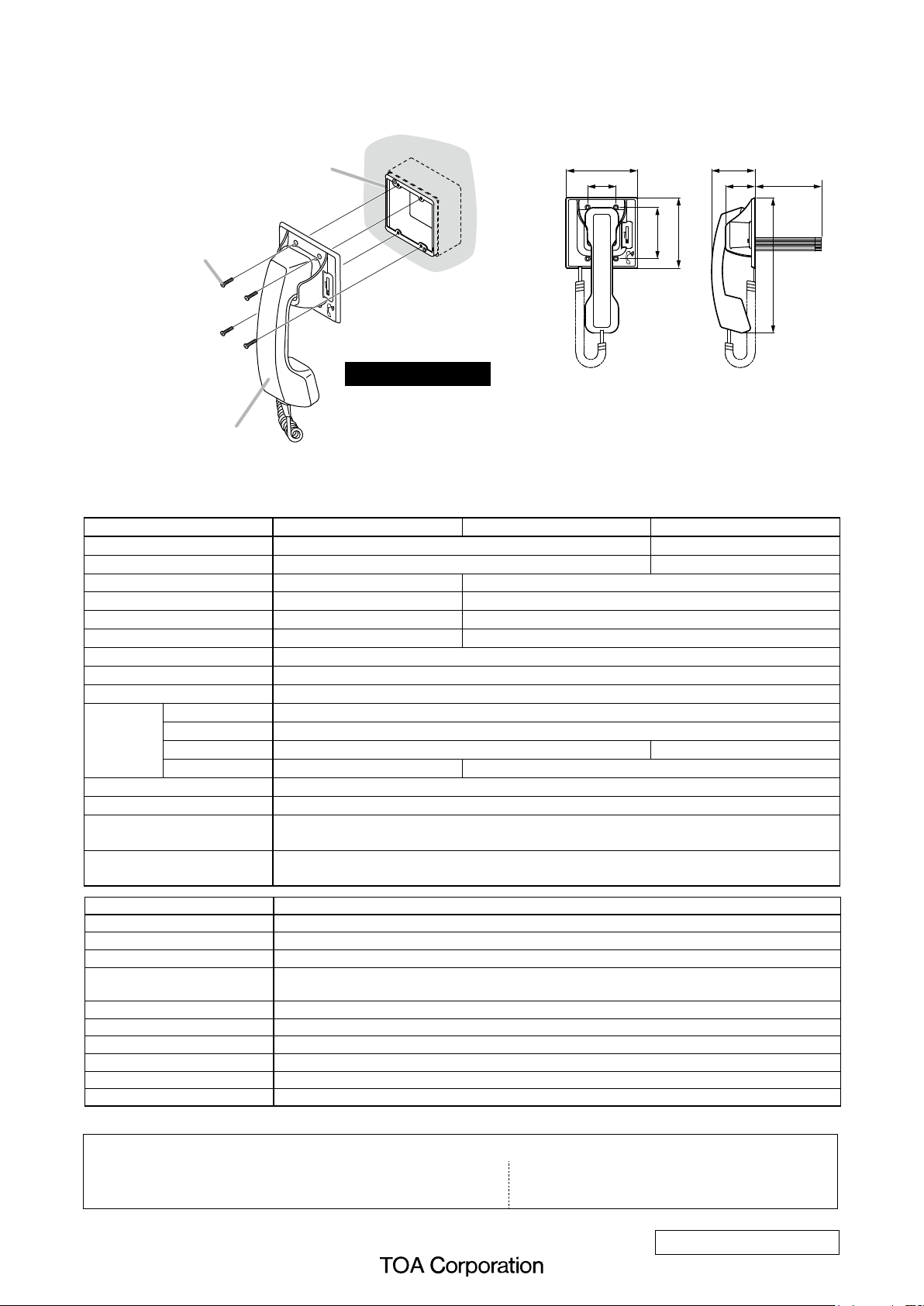
4.2. Option Handset Installation
Mount the option handset to an electrical box mounted in the wall.
116 71
46 48 200 or less
Unit: mm
83.5
115
220
RS-141
[Dimensional diagram]
YC-302
2-gang electrical box
(option)
Machine screw M4 x 25
(supplied with the RS-141)
Wall surface
Accessory screws
The RS-141 comes with 2 types of screws: M4 x 25 and UNC
No. 6-32 x 18.
For the electrical box provided with unified threads, use the
UNC No. 6-32 x 18.
Note: The design and specications are subject to change without notice for improvement.
133-06-00029-00

This manual suits for next models

3

Other Toa Handset manuals

Toa RS-190 User manual

Toa

Toa RS-190 User manual

Toa RS-110 User manual

Toa

Toa RS-110 User manual

Toa RS-191 User manual

Toa

Toa RS-191 User manual

Popular Handset manuals by other brands

Siemens Hicom 150 E optiset E basic operating instructions

Siemens

Siemens Hicom 150 E optiset E basic operating instructions

Aiphone LAR-1 Field installation guide

Aiphone

Aiphone LAR-1 Field installation guide

HOLMCO N40 Series RECOMMENDED OPERATION PRACTICES

HOLMCO

HOLMCO N40 Series RECOMMENDED OPERATION PRACTICES

Radio Shack 43-144 user guide

Radio Shack

Radio Shack 43-144 user guide

Uniden DCX170 Manual para el usuario

Uniden

Uniden DCX170 Manual para el usuario

Motorola L4 - DECT Cordless Handset quick start guide

Motorola

Motorola L4 - DECT Cordless Handset quick start guide

Avaya 4145E user guide

Avaya

Avaya 4145E user guide

Gigaset G2000C manual

Gigaset

Gigaset G2000C manual

Panasonic KX-TGP550 Quick reference guide

Panasonic

Panasonic KX-TGP550 Quick reference guide

Bpt YKP/200 Instructions for use and installation

Bpt

Bpt YKP/200 Instructions for use and installation

GE 27950 user guide

GE

GE 27950 user guide

SW Comms DK280 quick guide

SW Comms

SW Comms DK280 quick guide

Metrack MVT600 user guide

Metrack

Metrack MVT600 user guide

LG-Ericsson GDC-400H user guide

LG-Ericsson

LG-Ericsson GDC-400H user guide

Panasonic KX-TGA101C installation manual

Panasonic

Panasonic KX-TGA101C installation manual

Mitel 5602 user guide

Mitel

Mitel 5602 user guide

Tynetec 7202 Operator's guide

Tynetec

Tynetec 7202 Operator's guide

Panasonic KX-TGA470 installation manual

Panasonic

Panasonic KX-TGA470 installation manual

manuals.online logo
manuals.online logoBrands
  • About & Mission
  • Contact us
  • Privacy Policy
  • Terms and Conditions

Copyright 2025 Manuals.Online. All Rights Reserved.