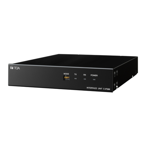
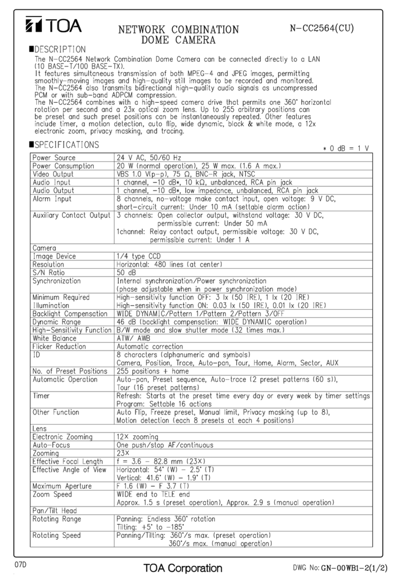
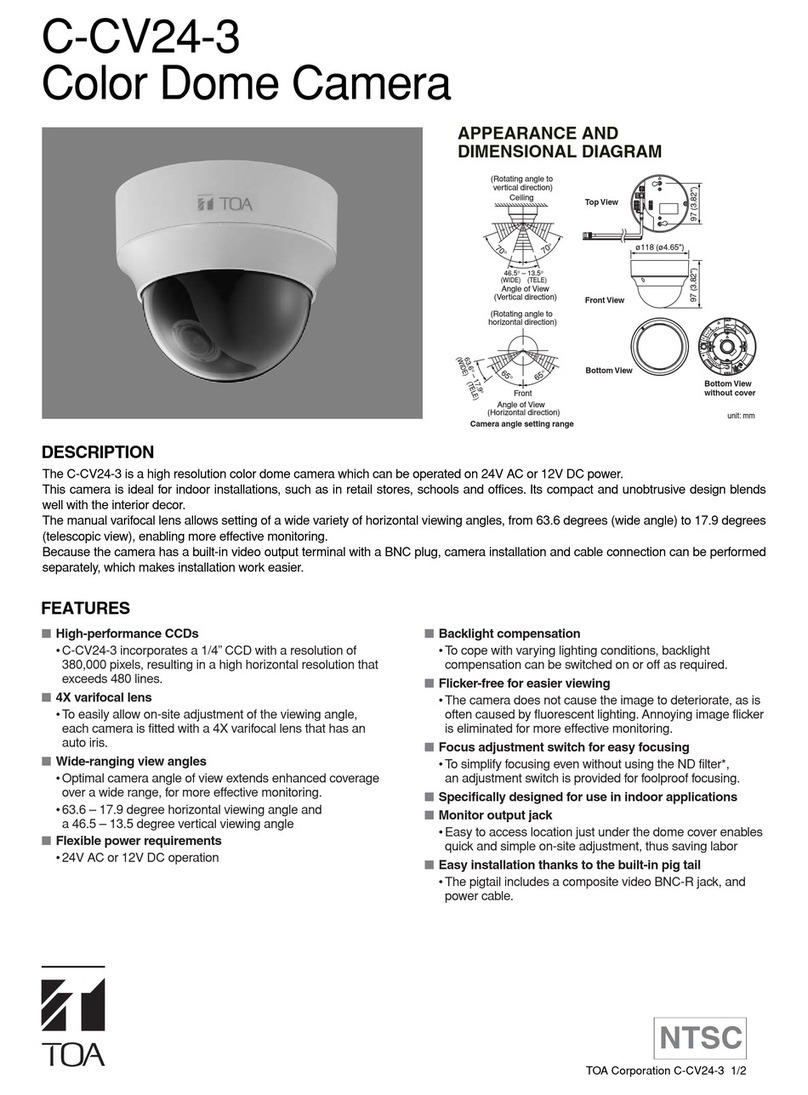
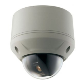
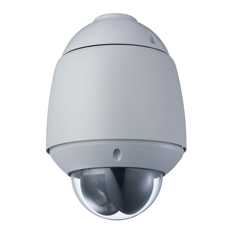
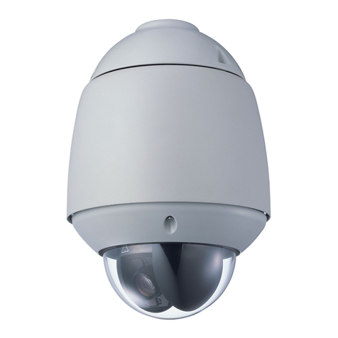
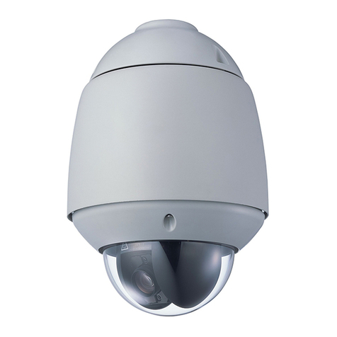
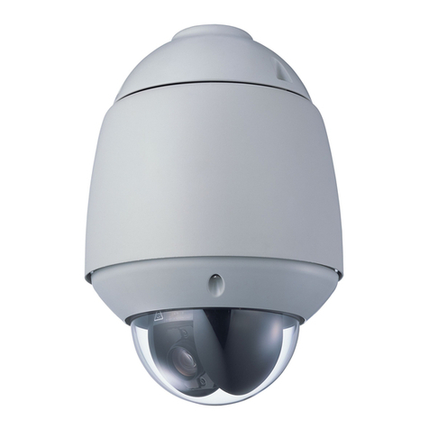
Toa C-CC704 CU User manual

COMBINATION CAMERA C-CC704 CU
For details regarding camera setting procedure, refer to the setting manual in the
manual CD supplied with the unit.
INSTALLATION MANUAL
Thank you for purchasing TOA’s Combination Camera. Please carefully follow the instructions in this
manual to ensure long, trouble-free use of your equipment.

2
TABLE OF CONTENTS
1. SAFETY PRECAUTIONS ............................................................................... 3
2. GENERAL DESCRIPTION ............................................................................. 6
3. FEATURES .......................................................................................................... 6
4. HANDLING PRECAUTIONS .......................................................................... 6
5. NOMENCLATURE ............................................................................................. 8
6. INSTALLATION PRECAUTIONS
6.1. Dip Switch Settings ........................................................................................... 9
6.1.1. Camera address setting switch (No. 1 – No. 6)...................................... 9
6.1.2. Communication method selector switch (No. 7)..................................... 9
6.1.3. Communication speed setting switch (No. 9).......................................... 9
6.1.4. Termination switch (No. 10).................................................................... 9
7. CONNECTIONS
7.1. Composite Cable Specifications ..................................................................... 11
7.1.1. Wiring specification ............................................................................... 11
7.2. Note on Camera Installation ........................................................................... 12
7.3. Camera Control Cable Connection ................................................................. 12
8. INSTALLATION
8.1. Cable Routing from the Ceiling ....................................................................... 13
8.2. Open Wring from the Camera's Side .............................................................. 17
9. SYSTEM EXAMPLES
9.1. Connection Example to the Digital Video Recorder ........................................ 18
9.2. Connection Example to the Multi-switcher ...................................................... 18
10. SPECIFICATIONS ............................................................................................. 19
Accessories ............................................................................................................. 20
Optional Products .................................................................................................... 20

3
Indicates a potentially hazardous situation which, if mishandled, could
result in death or serious personal injury.
WARNING
When Installing the Unit
• This is a class A product. In a domestic environment this product may cause radio interference in which case
the user may be required to take adequate measures.
• Use the unit only with the voltage specified on the unit. Using a voltage higher than that which is specified
may result in fire or electric shock.
• Do not cut, kink, otherwise damage nor modify the power supply cord. In addition, avoid using the power
cord in close proximity to heaters, and never place heavy objects -- including the unit itself -- on the power
cord, as doing so may result in fire or electric shock.
• Avoid installing or mounting the unit in unstable locations, such as on a rickety table or a slanted surface.
Doing so may result in the unit falling down and causing personal injury and/or property damage.
• Install the unit only in a location that can structurally support the weight of the unit and the mounting bracket.
Doing otherwise may result in the unit falling down and causing personal injury and/or property damage.
• Only use the unit's dedicated mounting hardware. The use of mounting hardware not designated could result
in the unit falling and possibly causing personal injury.
• Do not install the unit in the following locations to avoid a traffic accident or personal injury:
· Locations which block the driving of a car.
· Locations where the unit can strike your body or catch your cloth when getting on or down the car.
• To prevent lightning strikes, install the unit at least five meters away from a lightning rod, and yet within the
protective range (angle of 45°) of the lightning conductor. Lightning strikes may cause a fire, electric shock
or personal injury.
• Owing to the unit's size and weight, be sure that at least two persons are available to install the unit. Failure
to do so could result in personal injury.
• Do not use other methods than specified to mount the bracket. Extreme force is applied to the unit and the
unit could fall off, possibly resulting in personal injuries.
• Attach the safety wire to the unit. If not attached, the unit could fall off, resulting in personal injury.
• Use nuts and bolts that are appropriate for the ceiling's or wall's structure and composition. Failure to do so
may cause the unit to fall, resulting in material damage and possible personal injury.
1. SAFETY PRECAUTIONS
• Before installation or use, be sure to carefully read all the instructions in this section for correct and safe
operation.
• Make sure to observe the instructions in this manual as the conventions of safety symbols and messages
regarded as very important precautions are included.
• We also recommend you keep this instruction manual handy for future reference.
Safety Symbol and Message Conventions
Safety symbols and messages described below are used in this manual to prevent bodily injury and property
damage which could result from mishandling. Before operating your product, read this manual first and
understand the safety symbols and messages so you are thoroughly aware of the potential safety hazards.
Do not expose the unit to rain or an environment where it may be
splashed by water or other liquids, as doing so may result in fire or
electric shock.
WARNING
4
When Installing the Unit
• Tighten each nut and bolt securely. Ensure that the bracket has no loose joints after installation to prevent
accidents that could result in personal injury.
• Avoid installing the unit in locations exposed to sea breeze or corrosive gas. The unit or its mounts may be
subject to corrosion, that might cause it to fall or result in other accidents.
• Do not mount the unit in locations exposed to constant vibration. The mounting screws and/or bolts may be
loosened by excessive vibration, potentially causing the unit to fall, which could result in personal injury.
When the Unit is in Use
• If any of the following irregularities occurs, immediately switch off the power, and inform the shop from where
the unit was purchased. Further using the unit may result in fire or electric shock.
· If you detect smoke or a strange smell coming from the unit.
· If water or any metallic object gets into the unit.
· If the unit falls, or the unit case breaks.
· If the power supply cord is damaged (exposure of the core, disconnection, etc.)
· If nothing is displayed on the screen even when the ambient temperature exceeds 0 °C.
• To prevent a fire or electric shock, never open nor remove the unit case as there are high voltage
components inside the unit. Refer all servicing to qualified service personnel.
• Do not insert nor drop metallic objects or flammable materials in the ventilation slots of the unit's cover, as
this may result in fire or electric shock.
• Do not touch the unit during thunder and lightning, as this may result in electric shock.
Indicates a potentially hazardous situation which, if mishandled, could
result in moderate or minor personal injury, and/or property damage.
CAUTION
When Installing the Unit
• To avoid electric shock, be sure to switch off the power before power supply wiring work.
• Leave the installation of the unit to your TOA dealer because the installation requires expert experience and
skills. The unit may fall off if incorrectly installed, resulting in possible personal injury.
When the Unit is in Use
• Do not stand or sit on, nor hang down from the unit as this may cause it to fall down or drop, resulting in
personal injury and/or property damage.
• Switch off the power, and unplug the power supply plug from the AC outlet for safety purposes when
cleaning or leaving the unit unused for 10 days or more. Doing otherwise may cause a fire or electric shock.
• Have the unit checked periodically by the shop from where it was purchased. Failure to do so may result in
corrosion or damage to the unit or its mounting bracket that could cause the unit to fall, possibly causing
personal injury.
• Contact your TOA dealer as to the cleaning. If dust is allowed to accumulate in the unit over a long period of
time, a fire or damage to the unit may result.

5
Note
This equipment has been tested and found to comply with the limits for a Class A digital device,
pursuant to Part 15 of the FCC Rules. These limits are designed to provide reasonable protection
against harmful interference when the equipment is operated in a commercial environment.This
equipment generates, uses, and can radiate radio frequency energy and, if not installed and used in
accordance with the instruction manual, may cause harmful interference to radio communications.
Operation of this equipment in a residential area is likely to cause harmful interference in which case the
user will be required to correct the interference at his own expense.
Modifications
Any modifications made to this device that are not approved by TOA Corporation may void the authority
granted to the user by the FCC to operate this equipment.
CU version complies with Part 15 of the FCC Rules.

6
2. GENERAL DESCRIPTION
The dome-type color camera allows 360-degree horizontal rotation and combines with a high speed camera
drive that permits 200-degree horizontal rotation and vertical tilting per second and a 10x optical zoom lens.
Up to 64 arbitrary positions can be preset and such preset positions can be instantaneously repeated.
It also offers functions such as a 12x electronic zoom, trace, and tour.
3. FEATURES
• Digital signal processing realizes high resolution and high picture quality. The unit also features the video
memory that increases the electronic sensitivity up to 64 times and enables electronic zooming.
• Up to 64 camera positions can be preset.
• It is in full conformity with IP66 waterproof and dust-proof standards (provided that the optional Wall
Mounting Bracket C-BC704W and Pendant Adapter C-BC704PB are used in combination).
• Since the camera unit is constructed of die-cast aluminum alloy and its dome cover is made of
polycarbonate, the C-CC704 ensures high resistance to strong impacts.
4. HANDLING PRECAUTIONS
• Noise may appear on the monitor or preset camera positions may deviate with prolonged camera use. In
such cases, use the camera's refresh function to automatically refresh contacts and reestablish the home
position once a day, thus allowing any position deviation to be corrected. When correcting manually, execute
an initialization operation "Initialize" by the Remote Controller.
• It is recommended that the unit be installed in locations where the temperature is under 40°C, as the aging
of parts may shorten the product life with prolonged unit use under high temperature and high humidity.
• Since the airtightness of unit structure is high enough, moisture could get inside the camera, causing the
inside of the dome cover to fog. Ensure that the camera is installed under low humidity conditions.
• Be sure to use the unit with its power continuously kept on when the ambient temperature is under 0°C.
Turning the power on from off at temperatures below 0°C causes the unit to malfunction.
• Do not direct the camera lens to the sun, strong lighting, or reflected light. If strong light enters the lens, this
may cause the CCD's internal color filter to deteriorate, leading to image discoloration.
• When the subject in the horizontal direction is viewed in telephoto mode, it may not come into focus
smoothly.
• Do not install the unit in locations exposed to constant vibration. The unit is not designed for vehicle use. Do
not install the unit in a vehicle nor ship.
• Mount the unit to a concrete wall or robustly constructed wall surface that can sufficiently withstand the total
weight of the unit and bracket. When mounting the unit to a pole, pay special attention to the sway and
strength of the pole, and mount it securely at an appropriate height that will not cause the pole to sway and
possibly weaken it. Moreover, avoid mounting the unit to a pole on which other objects susceptible to wind
are also mounted.
• Bolts and nuts used to fix the unit to a ceiling, a wall or a pole are not included. Prepare those appropriate
for the materials and the strength of installation location, and strong enough to withstand the total weight of
the unit and bracket.
• Do not give the unit a great shock or vibration, as this will cause the unit to fail or break, or water to
penetrate into the unit.

7
• Avoid installing the unit on sea or shore, in dusty locations, or in locations exposed to corrosive gas,
herbicides or other sprayed liquid chemicals such as pools, or extraordinary combustible conditions.
• To prevent camera unit fall, connect the supplied safety wire to the case when installing the camera unit to
the case.
• The dome camera is designed solely for suspended installations. The camera or dome must be suspended
vertically with its dome facing downward. Use special care not to suspend it at a tilted angle.
• The unit is not equipped with a power switch. Perform power construction work so that the camera power
can be turned on and off remotely.
• When cleaning the unit, be sure to switch off the power. Wipe with a soft dry cloth. If it gets very dirty, use
the soft cloth slightly moistened in neutral cleanser. Never use thinner, benzene, or chemically processed
towels as the unit's resin or other parts may be deformed or discolored.
• When cleaning the dome cover, wipe lightly with a soft cloth. In this event, the cover could be scratched and
damaged if the dome is covered in dust or sand. When the cover is extremely dirty, it is highly recommended
that the cover be removed and that its outside surface be washed lightly with water. Since alcohol-based
detergents can turn the dome cover whitish, avoid using them, as camera picture quality could be severely
affected.
• When dust has settled on the unit's lens, lightly clean using a commercial camera blower or cleaning paper.

8
[Back side of the case ]
[Top view of the camera unit ]
5. NOMENCLATURE
Case
Camera unit
Dome cover
Input/output connector
Power supply connector
DIP switch
Pipe receptacle cover

9
ON
12345678910
6.1. Dip Switch Settings
To control the unit, the address number and communication parameters must be set by the DIP switch on top
of the camera unit.
Camera address setting switch 1
Camera address setting switch 2
Camera address setting switch 3
Camera address setting switch 4
Camera address setting switch 5
Camera address setting switch 6
Communication method selector switch
Unused
No.1
No.2
No.3
No.4
No.5
No.6
No.7
No.8
Communication speed setting switch
No.9
Termination switch
No.10
6.1.1. Camera address setting switch (No. 1 – No. 6)
Sets the camera address for use in connection to the Remote Controller. Set the address number to be the
same as the channel number of the switcher to be connected. For the relationship between the switch settings
and camera addresses, refer to the table on p. 10. (Factory preset: Only No. 1 is set to ON.)
6.1.2. Communication method selector switch (No. 7)
Used to select RS-485 communication method. Allows changing between Type A and Type B.
OFF: Type A, ON: Type B (Factory preset: ON)
6.1.3. Communication speed setting switch (No. 9)
Check to make sure that this speed is set identical to the communication speed set to
the Remote Controller. When changing the communication speed, change settings for
all the cameras and Remote Controllers within the system. (Factory preset: 38,400 bps)
6.1.4. Termination switch (No. 10)
Set this switch to the ON position for the camera which is terminated in the end of the RS-485's control line.
(Factory preset: OFF)
No.9 bps
OFF 38,400
O N 9,600
Notes
• Mount the unit to a heavy-duty ceiling surface (such as concrete ceiling).
• When installing the camera in the ceiling to hide it as much as possible, use the optional C-BC704U Flush
Ceiling Mount bracket.
• When mounting the camera to a wall, use the optional C-BC704W Wall Mounting Bracket.
• When suspending the camera from a ceiling, attach it to the suspension pipe using the optional C-BC704PB
Pendant Adapter.
• When mounting the camera to a pole, use the optional C-BC704W Wall Mounting Bracket in conjunction
with the optional C-BC771PM Pole Mounting Bracket.
6. INSTALLATION PRECAUTIONS
The unit weighs 1.8 kg. Select the heavy-duty mounting surface that
can structurally support the total weight of the unit and bracket. Doing
otherwise may result in the unit falling and possibly causing personal
injury.
WARNING

10
ON
12345678910
ON
12345678910
ON
12345678910
ON
12345678910
ON
12345678910
ON
12345678910
ON
12345678910
ON
12345678910
ON
12345678910
ON
12345678910
ON
12345678910
ON
12345678910
ON
12345678910
ON
12345678910
ON
12345678910
ON
12345678910
ON
12345678910
ON
12345678910
ON
12345678910
ON
12345678910
ON
12345678910
ON
12345678910
ON
12345678910
ON
12345678910
ON
12345678910
ON
12345678910
ON
12345678910
ON
12345678910
ON
12345678910
ON
12345678910
ON
12345678910
ON
12345678910
ON
12345678910
ON
12345678910
ON
12345678910
ON
12345678910
ON
12345678910
ON
12345678910
ON
12345678910
ON
12345678910
ON
12345678910
ON
12345678910
ON
12345678910
ON
12345678910
ON
12345678910
ON
12345678910
ON
12345678910
ON
12345678910
ON
12345678910
ON
12345678910
ON
12345678910
ON
12345678910
ON
12345678910
ON
12345678910
ON
12345678910
ON
12345678910
ON
12345678910
ON
12345678910
ON
12345678910
ON
12345678910
ON
12345678910
ON
12345678910
ON
12345678910
1173349
2183450
3193551
4203652
5213753
6223854
7233955
8244056
9254157
10 26 42 58
11 27 43 59
12 28 44 60
13 29 45 61
14 30 46 62
15 31 47 63
16 32 48
DIP switch DIP switch DIP switch DIP switch
No. No. No. No.
[Camera address setting switch: 1 – 63 ]

11
Power input terminal
Connect this terminal to 24 V AC. (50/60 Hz)
Video output terminal (No. 1 and No. 2)
Connect to the video input terminal of the monitor,
digital video recorder, or multi-switcher.
Alarm input terminal (No. 6 – No. 9)
Connect to the sensor with no-voltage make contact output or
the external equipment that provides an contact control output.
Camera control terminal (No. 3 and No. 4)
Connect to the RS-485 control line from the Remote Controller
or the other camera.
1
2
3
4
5
6
7
8
9
VIDEO
GND
RS485 +
RS485
-
GND
AL1
AL2
AL3
AL4
Terminal name
[ Power supply connector ]
[ Input/output connector ]
7.1. Composite Cable Specifications
Video output cable
Power supply cable
Camera control cables
Alarm input cables
Input/output connector
Power supply connector
Input/output connector
Terminal No. Terminal name Cable color Terminal
treatment
1 VIDEO Yellow BNC jack
2 GND Shield
3 RS485 + Green Bare end
4 RS485
-
Blue Bare end
5 GND White Bare end
6 AL1 Brown Bare end
7 AL2 Purple Bare end
8 AL3 Orange Bare end
9 AL4 Gray Bare end
Power supply connector
Terminal No. Terminal name Cable color Terminal
treatment
1 24 V AC Red AC adapter
jack
2 24 V AC Black
Note
A ground common to AL1 – AL4 (terminal No. 6 – No. 9)
is assigned to Terminal No. 5, GND terminal (white cable)
of the Input/Output terminal. Pair each of AL1 – AL4 with
Terminal No.5 for connection of the alarm input.
7.1.1. Wiring specification
7. CONNECTIONS

12
7.3. Camera Control Cable Connection
• Connect camera control terminals "+" and "
-
" (RS-485)of the Remote Controller or the Interface Unit to the
camera's camera control terminals "+" and "
-
", respectively.
• Sequentially connect the camera's camera control terminals "+" and "
-
" to the next camera's camera control
terminals "+" and "
-
."
• Connect the GND cable in the figure below to the Camera Input/Output Connector Terminal No. 5, GND
terminal (white cable).
Notes
• The maximum number of units connectable to a pair of RS-485 lines (from termination to termination)is 32
units including the Remote Controller. The maximum cable length connecting each terminal is 1.2 km in
total.
• The camera may not operate correctly if 32 or more units are connected or the total cable distance exceeds
1.2 km. In such cases, split or extend wiring using the C-IF500 Interface Unit.
Shield twisted pair cable
Camera control
cable
Connect to the next
camera's camera
control terminal.
Connect to Remote
Controller's camera
control terminal.
Camera control
cable
GND
GND
7.2. Note on Camera Installation
• Be sure to seal and insulate each connection of the video output cable, power supply cable, control cable,
and alarm cable with each corresponding cable from the other equipment using the waterproof tape. Perform
the wiring paying attention not to touch the peripheral metal parts.
Monitor, Digital video recorder
Remote controller
AC adapter
Insulate each cable with the waterproof tape.
• Avoid installing the camera cables in close proximity to fluorescent lamps or other electrical appliances.
Failure to do this can downgrade the picture quality.
• If there is a strong electric or magnetic field near the camera, such as television transmission antennas,
motors or transformers, this may distort or roll the monitor picture. In such cases, run the entire wiring route
through metal conduit tubing.
• Before applying the power to the camera, be sure to complete all connections between the camera and
related equipment.

13
8. INSTALLATION
8.1. Cable Routing from the Ceiling
Note: Be sure to switch off the power when installing the camera.
1. Make a hole in the ceiling panel, then pull out the cable through it.
2. Run the cables extending from the ceiling through the cable entry hole on the upper side of the case, then
secure the case to the ceiling.
Use screws with a nominal diameter of 4 mm and a length of over 25 mm.
Notes
• When installing the camera, ensure that ceiling is strong enough to withstand the camera load.
• Mounting screws are not supplied with the unit. Separately prepare the screws that are strong enough to
withstand the camera load depending on the installation conditions.
• The 4 camera mounting points must be waterproofed with silicone sealant.

14
Buffer material
Camera Unit
Composite cable
3. When installing the camera, ensure that ceiling is strong enough to withstand the camera load.
Note: Be sure to seal and insulate each connection of the cable with waterproof tape.
4. Remove the buffer material for transportation from the camera unit.

15
Safety wire
Dome cover fixing screw
(accessory)
Camera unit
Dome cover
5. Attach the dome cover to the camera unit.
6. Perform DIP switch settings.
For switch settings, refer to p. 9.
7. Connect the safety wire secured to the camera unit to the case.

16
TORX wrench
Align the positioning marks.
Composite cable
8. Connect the composite cable connected to the cables extended from the ceiling to the camera unit.
9. Secure the camera section (camera unit + dome cover)to the case using the supplied TORX wrench.
Align the positioning marks on both rear sides.

17
Detach
Attach
Approx. 100 mm
Sealing tape
Pipe
8.2. Open Wiring from the Camera's Side
1. Detach the pipe receptacle cover on the camera side, then attach it to the case's top surface.
2. Wrap two or more turns of sealing tape around the pipe's threaded section, then screw the pipe into the
camera's threaded receptacle.
• Sealing tape must be wrapped around the pipe's threaded part.
• The pipe receptacle thread is compatible with NPT3/4 as specified in ANSI/ASME B1.20.1 (The American
Standard Taper Pipe Threads).
3. Run the cables through the pipe, pull them out from the case opening, then secure the case to the ceiling.
Use screws with a nominal diameter of 4 mm and a length of over 25 mm. For the details of the mounting
holes, refer to p. 13. Join the pipe mounted to the camera to an extension pipe using a coupling.
Notes
• Mounting screws are not supplied with the unit. Separately prepare the screws that are strong enough to
withstand the camera load depending on the installation locations.
• The 4 camera mounting points must be waterproofed with silicone sealant.
4. As the mounting methods of the camera unit and the dome cover are the same as those when routing the
cable from the ceiling, refer to p. 14.

18
Monitor
Digital video recorder
Remote controller
Combination camera
Combination camera
Monitor
Multi-switcher
Remote controller
Combination camera
Combination camera
9. SYSTEM EXAMPLES
9.1. Connection Example to the Digital Video Recorder
Note
It is possible to use the Combination Cameras in any combination.
When using the Combination Cameras in combination with the fixed cameras, only screen control is possible
by the switcher as for the fixed camera channels.
9.2. Connection Example to the Multi-switcher

19
10. SPECIFICATIONS
Power Source 24 V AC, 50/ 60 Hz
Power Consumption 11 W
Control RS-485 communications system (applicable protocol: Type A , Type B)
Video Output VBS 1.0 V(p-p), 75 Ω
Camera Control Terminal RS-485 camera control connector
Alarm Input 4-channels, no-voltage make contact input, open voltage: 5 V DC,
short-circuit current: 8 mA or less (settable alarm action)
Synchronization Internal synchronization
ID 8 characters (alphanumeric and symbols), Camera, Position, Trace, Auto-pan, Tour, Sector
No. of Preset Positions 64
Automatic Operation Auto-pan, Auto-trace (8 preset patterns (120 s)), Tour (8 preset patterns)
Timer Refresh: Starts at the preset time every day by timer settings
Language English, Japanese
Camera
Image Device 1/4 type CCD
Resolution Horizontal: 470 lines (at center)
Number of Effective Pixels 768 (H)x 494 (V)(
380,000 pixels)
Scanning System 2 : 1 interlace
Scanning Frequency Horizontal: 15.734 kHz, Vertical: 59.94 Hz
S/N Ratio 50 dB
Minimum Illumination High-sensitivity function OFF: 2 lx (50 IRE), 0.4 lx (20 IRE)
High-sensitivity function ON: 0.1 lx (50 IRE), 0.03 lx (20 IRE)
Backlight Compensation ON/ OFF
High-Sensitivity Function Slow shutter mode (64 times max.)
White Balance ATW/ AWB
Iris Automatic
Flicker Reduction Automatic correction
Electronic Zooming 12 x zooming
Auto-Focus Stop AF
Lens
Zooming 10 x
Effective Focal Length f = 3.8
-
38 mm (10 x)
Effective Angle of View Horizontal: 50.7° (W)
-
5.4° (T), Vertical: 39.1° (W)
-
4.1° (T)
Maximum Aperture F 1.8 (W)
-
2.4 (T)
Zoom Speed WIDE end to TELE end, Approx. 2.1 s (preset operation), Approx. 2.1 s (manual operation)
Pan/Tilt Head
Rotating Range Panning: Endless 360° rotation, Tilting: +2° to
-
90°
Rotating Speed Panning/ Tilting: 200°/s max. (preset operation), 200°/s max. (manual operation)
Operating Temperature
-
10°C to +50°C (14°F to 122°F)
(The power needs to be continuously kept on under 0°C (32°F))
Operating Humidity 90%RH or less (no condensation)
Application Indoors
Dust/Water Protection IP66 (*1)
Finish Case, decorative frame:, Die-cast aluminum, light gray, paint
Dome cover: PC resin (transparent)
Dimensions Camera section external diameter: ø157 x 159 (H)mm (ø6.18" x 6.26" (H))
Dome external diameter: ø99 mm (ø3.90")
Weight 1.8 kg (3.97 lb)
(*1) Provided that the optional C-BC704W and C-BC704PB are used in combination.
Note: The design and specifications are subject to change without notice for improvement.

• Accessories
CD-R (Instruction manual in PDF)............. 1
Dome cover fixing screw M4 x 10 .............. 3
Composite cable ........................................ 1
TORX wrench ............................................. 1
Sealing tape ............................................... 1
• Optional products
Wall Mounting Bracket: C-BC704W
Pole Mounting Bracket: C-BC771PM
Flush Ceiling Mounting Bracket: C-BC704U
Pendant adapter: C-BC704PB
Mounting Band: YS-60B
133-22-209-4C
URL: http://www.toa.jp/
Other manuals for C-CC704 CU
1
Table of contents
Other Toa Security Camera manuals

Toa
Toa C-CV202-3 CU User manual

Toa
Toa Q-CV24VP-3 User manual

Toa
Toa C-CC514 NT User manual

Toa
Toa C-CC364 User manual

Toa
Toa C-CV454D-9 CU User manual

Toa
Toa C-CC364 User manual

Toa
Toa C-CV14-CS User manual

Toa
Toa C-CV854D-3 CE User manual

Toa
Toa C-CV44-3 NTSC User manual

Toa
Toa Netcansee N-CC2564 User manual

Toa
Toa Netcansee N-CC2360 User manual

Toa
Toa C-CV24-3 User manual

Toa
Toa C-CC704 Operating and installation instructions

Toa
Toa C-CV24-2 NTSC User manual

Toa
Toa C-CV102-CS User manual

Toa
Toa N-VT1010 L User manual

Toa
Toa C-CC704 CU User guide

Toa
Toa Netcansee N-CC2564 Guide

Toa
Toa Netcansee N-CC2564 User manual

Toa
Toa C-CC364 NT User guide