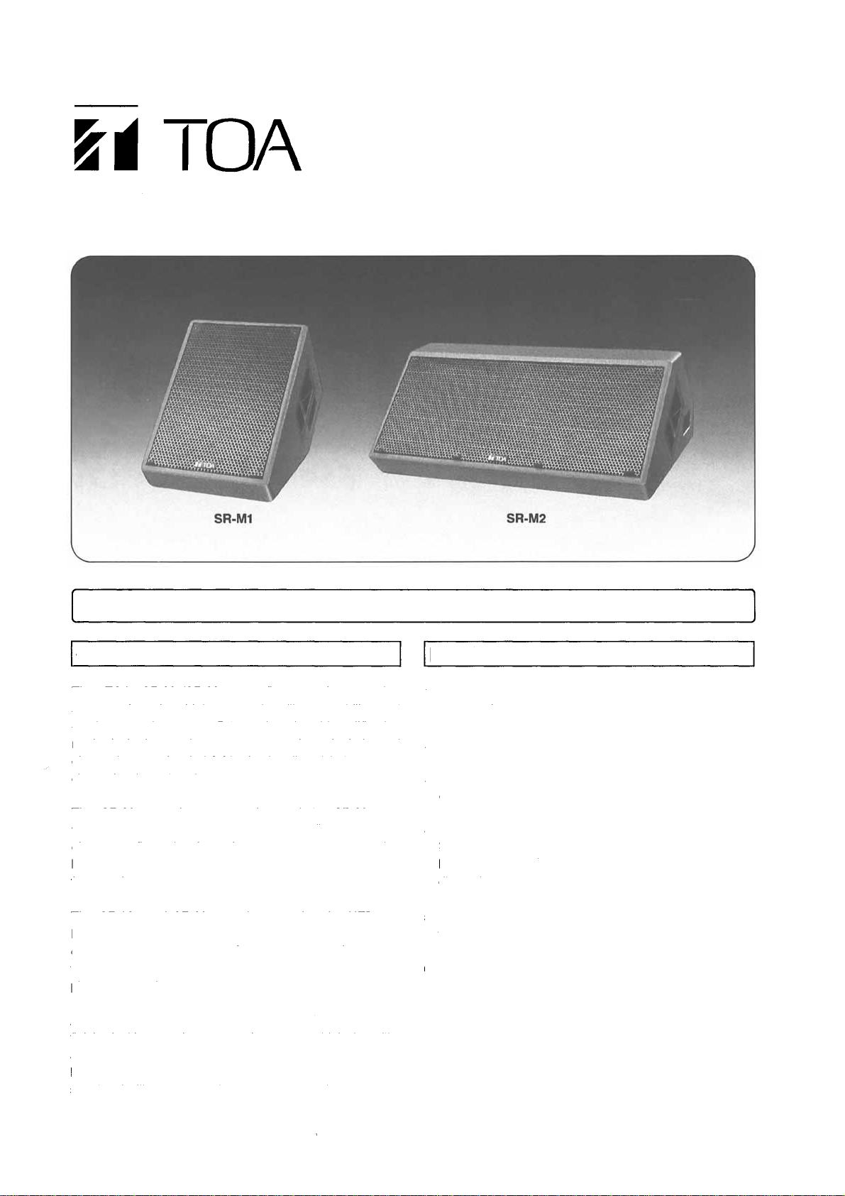
manuals.online logo
Brands
  1. Home
  2. •
  3. Brands
  4. •
  5. Toa
  6. •
  7. Speakers System
  8. •
  9. Toa SR-M1 User manual

Toa SR-M1 User manual

INSTRUCTION MANUAL
SR-M1
SR-M2
FLOOR MONITOR SPEAKER SYSTEMS
The AC-M1 electronic control unit (optional) is required when using the SR-M1 or SR-M2 speaker syste .
GENERAL DESCRIPTION FEATURES
The TOA SR-M1/SR-M2 are floor onitor speaker
syste s featuring high power handling capability and
quality sound output. Driven by the bia plification
ethod, both speaker syste s need a dual-channel
electronic control unit AC-M1 (optional) which features a
channel dividing function.
The SR-M1 contains one woofer, and the SR-M2 two
woofers. The woofer e ploys a 20 c (7.9") agnet that
gives a flux density of 16,200 gauss, assuring
highly-efficient, quick-response reproduction of low
frequencies.
The SR-M1 and SR-M2 speakers e ploy the HFD-652
high-power driver unit with a titaniu diaphrag , and the
constant directivity horn (40° horizontal by 40° vertical),
the co bination of which provides unifor distribution of
pleasant sound.
Apiton plywood enclosure (18 , 0.7" in thickness)
finished with rugged epoxy coating ensures high durability
and excellent acoustic characteristics. Also, Neutrik's
NL4MPR input connectors located on both sides of the
speaker facilitate a cascade speaker connection.
1.High power handling capability and heavy-duty
construction.
2. Bia plification syste .
3. Highly efficient 30c (12') woofer e ploying a 200
(7.9") dia eter agnet.
4. Large, high-power driver with a titaniu diaphrag for
high-range coverage. A constant directivity horn (40°
horizontal by 40° vertical) ensures a unifor sound
dispersion pattern.
5. Apiton plywood enclosure (18 , 0.7" in thickness)
with rugged epoxy coating.
6. Two Neutrik NL4MPR input connectors.
TOA Corporation
INPUT CONNECTORS
Two Neutrik NL4MPR connectors are provided on both sides of the speaker. Because they are internally
parallel-connected, you can use either of the two.
Each contact of the connector is wired as shown in the following table.
The LOW input i pedance is 8 oh s for both the SR-M1 and SR-M2. (In the SR-M2, two 16 oh woofers
are internally parallel-connected at the LOW input.)
Applicable cable connector: Neutrik NL4FC
CONNECTION
Basic Connection B ock Diagram
Power amp ifier types to use
With the bia plification syste being e ployed, dual-channel power a plifiers ust be used to drive the
SR-M1 or SR-M2. Be sure to use a 300W (at 8 oh load) or ore powerful a plifier per channel. If
s aller-power a plifiers are used, the speaker's original perfor ance will suffer.
Para e connection of two speakers
Two speakers can be connected in parallel using the input connectors on both sides of each speaker, as
shown below. To connect two speakers in parallel, the a plifier output power ust be 450W or ore (at 4
oh load).
Parallel-connection of two SR-M1
Parallel-connection of two SR-M2
Contact nu ber
1 +
1 -
2 +
2 -
SR-M1/SR-M2
LOW +
LOW -
HIGH
+
HIGH
-
Mixer/
Preamp ifier
INPUT 1
Mixer/
Preamp ifier
INPUT 2
(CH1)
(CH2)
LOW SENSE 1
LOW OUT 1
HIGH OUT 1
HIGH SENSE 1
LOW SENSE 2
LOW OUT 2
HIGH OUT 2
HIGH SENSE 2
AC-M1
POWER AMP
POWER AMP
LOW
HIGH
LOW
HIGH
SR-M1 or SR-M2
SR-M1 or SR-M2
Connection precaution
Neither the SR-M1 or SR-M2 has an internal circuit to protect a high-range driver. If the LOW signal is input
to the high-range driver due to wrong connection, the driver ay be da aged. To avoid this, carefully check
for proper connection before use.
INSTALLATION
The SR-M1 and SR-M2 are designed for installation on flat floor.
SR-M1
SR-M2
The AC-M1 electronic control unit has an internal equalizer to ensure the opti u sound output when the
speaker is installed as shown above. In addition, the control unit is equipped with the FC (Floor Correction)
switch to ini ize the influence of reflected waves produced when the speaker is directly installed on the
floor. (For ore details, refer to the AC-M1 Instruction Manual.) Usually, set the FC switch to IN.
AC-M1
e ectronic
contro
unit
(optiona )
The optional AC-M1 control unit features the following functions for the best possible sound reproduction
fro the SR-M1 and SR-M2 speakers:
Channel divider
Phase atching /ti e align ent
Equalizer
Li iter
Floor correction
CHARACTERISTIC
DIAGRAMS
(1/3
Octave
Pink
Noise)
SR-M1 (1/4 W input/1 m, at 2 kHz of HIGH frequency)
SR-M2 (1/4 W input/1 m, at 2 kHz of HIGH frequency)
SPECIFICATIONS
Mode
Enclosure
Speaker
Low Frequency
High Frequency
No inal I pedance
Sensitivity
Frequency Response
Crossover Frequency
Power Handling
Capacity
Low Frequency
High Frequency
Input Connector
Enclosure Material
Weight
Di ensions (W
Finish
Accessories
SR-M1
SR-M2
Bass reflex type
30 c (12") dia. cone speaker × 1
30 c (12") dia. cone speakers x 2
CD horn (40° horizontal × 40° vertical) fitted with co pression driver
Low frequency : 8
High frequency : 16
Low frequency : 99 dB (1W/1 ) (*1)
High frequency : 109 dB (1W/1 ) (*2)
70 ~ 20,000 Hz (when AC-M1 is used)
Low frequency : 82, parallel-connection)
High frequency : 1
Low frequency : 102 (1W/1 ) dB (*1)
High frequency : 109 (1W/1 ) dB (*2)
45 ~ 20,000 Hz (when AC-M1 is used)
1 kHz (when AC-M1 is used)
Continuous pink noise : 120 W RMS (*3)
Continuous progra : 360 W RMS
Continuous pink noise : 80 W RMS (*4)
Continuous progra : 240 W RMS
Continuous pink noise : 240 W RMS (*3)
Continuous progra : 720 W RMS
Continuous pink noise : 80 W RMS (*4)
Continuous progra : 240 W RMS
Neutrik NL4MPR × 2
APITON plywood (thickness: 18 or 0.7")
Approx. 32 kg (71 Ib.)
390 × 439 × 662 (15.4" × 17.3" × 26.1 ")
Approx. 56kg (123lb.)
902 x 346 x 618 (35.5 " × 13.6 " × 24.3")
Enclosure : Epoxy paint (black)
Front grille : Acrylic paint (black)
Instruction anual ×1
Warranty card ×1
*1 Band Li ited (200 to 1,000 Hz) Pink noise signal
*2 Band Li ited (1,000 to 5,000 Hz) Pink noise signal
*3 Band Li ited (50 to 1,000 Hz) Pink noise signal (24 hours)
*4 Band Li ited (1,000 to 20,000 Hz) Pink noise signal (24 hours)
* Specifications are subject to change without notice.
APPEARANCE
SR-M1
SR-M2
TOA Corporation
PRINTED IN JAPAN
133-01-365-80
(16 ×

This manual suits for next models

1

Other Toa Speakers System manuals

Toa BS-20 User manual

Toa

Toa BS-20 User manual

Toa CS-64 User manual

Toa

Toa CS-64 User manual

Toa F-505W User manual

Toa

Toa F-505W User manual

Toa F-2000BTWP User manual

Toa

Toa F-2000BTWP User manual

Toa FB-120B User manual

Toa

Toa FB-120B User manual

Toa SF-60 User manual

Toa

Toa SF-60 User manual

Toa F-2322C2 User manual

Toa

Toa F-2322C2 User manual

Toa SM-60 User manual

Toa

Toa SM-60 User manual

Toa F-1300B User manual

Toa

Toa F-1300B User manual

Toa SR-F04 User manual

Toa

Toa SR-F04 User manual

Toa 22-ME-AV User manual

Toa

Toa 22-ME-AV User manual

Toa F-122C User manual

Toa

Toa F-122C User manual

Toa SM-25A User manual

Toa

Toa SM-25A User manual

Toa PJ-304 User manual

Toa

Toa PJ-304 User manual

Toa F-505 User manual

Toa

Toa F-505 User manual

Toa F-500WP User manual

Toa

Toa F-500WP User manual

Toa SR-C8L User manual

Toa

Toa SR-C8L User manual

Toa F-1000WTWP EB-Q User manual

Toa

Toa F-1000WTWP EB-Q User manual

Toa F-122CU2 User manual

Toa

Toa F-122CU2 User manual

Toa HS-212 User manual

Toa

Toa HS-212 User manual

Toa F-1000BTWP EB-Q User manual

Toa

Toa F-1000BTWP EB-Q User manual

Toa SR-F08 User manual

Toa

Toa SR-F08 User manual

Toa 30-SD User manual

Toa

Toa 30-SD User manual

Toa F-5 US User manual

Toa

Toa F-5 US User manual

Popular Speakers System manuals by other brands

JVC 0405MWMMDWBET instructions

JVC

JVC 0405MWMMDWBET instructions

Pioneer S-4EX operating instructions

Pioneer

Pioneer S-4EX operating instructions

APOGEE ACOUSTICS Diva Owner's manual and assembly instructions

APOGEE ACOUSTICS

APOGEE ACOUSTICS Diva Owner's manual and assembly instructions

Kogan KASBD513MA user guide

Kogan

Kogan KASBD513MA user guide

Vizio SB4451-C0 quick start guide

Vizio

Vizio SB4451-C0 quick start guide

Microlab FC360 5.1 user manual

Microlab

Microlab FC360 5.1 user manual

Bose L1 Model II owner's guide

Bose

Bose L1 Model II owner's guide

Speco SP6MAT Specification sheet

Speco

Speco SP6MAT Specification sheet

Somogyi SAL PAB25A instruction manual

Somogyi

Somogyi SAL PAB25A instruction manual

Yamaha NS 125F - Bass-Reflex Tower Speakers owner's manual

Yamaha

Yamaha NS 125F - Bass-Reflex Tower Speakers owner's manual

Bose Acoustimass 15 Series II Guide

Bose

Bose Acoustimass 15 Series II Guide

JAMO C 401 instructions

JAMO

JAMO C 401 instructions

Alpine PSU-300ACD installation manual

Alpine

Alpine PSU-300ACD installation manual

Samsung HW-J450-TK user manual

Samsung

Samsung HW-J450-TK user manual

auna multimedia Areal Bar 460 manual

auna multimedia

auna multimedia Areal Bar 460 manual

Onkyo SKW-501 instruction manual

Onkyo

Onkyo SKW-501 instruction manual

MartinLogan Motion Vision X quick start guide

MartinLogan

MartinLogan Motion Vision X quick start guide

Philips MMS 506 Instructions for use

Philips

Philips MMS 506 Instructions for use

manuals.online logo
manuals.online logoBrands
  • About & Mission
  • Contact us
  • Privacy Policy
  • Terms and Conditions

Copyright 2025 Manuals.Online. All Rights Reserved.