manuals.online logo
Brands
  1. Home
  2. •
  3. Brands
  4. •
  5. TOHATSU
  6. •
  7. Outboard Motor
  8. •
  9. TOHATSU M 70C User manual

TOHATSU M 70C User manual

Other TOHATSU Outboard Motor manuals

TOHATSU MFS 30B User manual

TOHATSU

TOHATSU MFS 30B User manual

TOHATSU MFS 8A3 User manual

TOHATSU

TOHATSU MFS 8A3 User manual

TOHATSU M 6B User manual

TOHATSU

TOHATSU M 6B User manual

TOHATSU M 4C User manual

TOHATSU

TOHATSU M 4C User manual

TOHATSU BFT 250A User manual

TOHATSU

TOHATSU BFT 250A User manual

TOHATSU MFS 2.5B User manual

TOHATSU

TOHATSU MFS 2.5B User manual

TOHATSU 5 B User manual

TOHATSU

TOHATSU 5 B User manual

TOHATSU MD 40B2 User manual

TOHATSU

TOHATSU MD 40B2 User manual

TOHATSU MFS 2.5B User manual

TOHATSU

TOHATSU MFS 2.5B User manual

TOHATSU 2 Stroke 9.9D2 User manual

TOHATSU

TOHATSU 2 Stroke 9.9D2 User manual

TOHATSU M 40D2 User manual

TOHATSU

TOHATSU M 40D2 User manual

TOHATSU BFT 150A User manual

TOHATSU

TOHATSU BFT 150A User manual

TOHATSU M 115A2 User manual

TOHATSU

TOHATSU M 115A2 User manual

TOHATSU MFS 25C User manual

TOHATSU

TOHATSU MFS 25C User manual

TOHATSU MFS 15C User manual

TOHATSU

TOHATSU MFS 15C User manual

TOHATSU M 4C User manual

TOHATSU

TOHATSU M 4C User manual

TOHATSU 9.9 User manual

TOHATSU

TOHATSU 9.9 User manual

TOHATSU 2.5 User manual

TOHATSU

TOHATSU 2.5 User manual

TOHATSU MFS 25d User manual

TOHATSU

TOHATSU MFS 25d User manual

TOHATSU BFT 200D Quick start guide

TOHATSU

TOHATSU BFT 200D Quick start guide

TOHATSU BFT 115A User manual

TOHATSU

TOHATSU BFT 115A User manual

TOHATSU MFS 6C User manual

TOHATSU

TOHATSU MFS 6C User manual

TOHATSU BFT 115A User manual

TOHATSU

TOHATSU BFT 115A User manual

TOHATSU MFS 9.9E Series User manual

TOHATSU

TOHATSU MFS 9.9E Series User manual

Popular Outboard Motor manuals by other brands

Yamaha VF150 owner's manual

Yamaha

Yamaha VF150 owner's manual

Sleipner SEP-IP30 installation guide

Sleipner

Sleipner SEP-IP30 installation guide

Suzuki DF 40 Service manual

Suzuki

Suzuki DF 40 Service manual

SELVA MARINE Corse owner's manual

SELVA MARINE

SELVA MARINE Corse owner's manual

KONRAD Series 600B Maintenance manual

KONRAD

KONRAD Series 600B Maintenance manual

Mercury 8 Bigfoot 4-Stroke Installation operation maintenance warranty manual

Mercury

Mercury 8 Bigfoot 4-Stroke Installation operation maintenance warranty manual

Sleipner E-Vision Electric Thruster E300 installation guide

Sleipner

Sleipner E-Vision Electric Thruster E300 installation guide

Suzuki DF40A manual

Suzuki

Suzuki DF40A manual

IST 18.BF200D manual

IST

IST 18.BF200D manual

Side-Power SP 155 TC i Installation and user manual

Side-Power

Side-Power SP 155 TC i Installation and user manual

Mercury 40 FourStroke Operation and maintenance manual

Mercury

Mercury 40 FourStroke Operation and maintenance manual

Quick BTR250 user manual

Quick

Quick BTR250 user manual

Yamaha VF90 owner's manual

Yamaha

Yamaha VF90 owner's manual

Yamaha D150H owner's manual

Yamaha

Yamaha D150H owner's manual

Yanmar ZT350 series Operation manual

Yanmar

Yanmar ZT350 series Operation manual

MotorGuide X3-40 Operation and maintenance manual

MotorGuide

MotorGuide X3-40 Operation and maintenance manual

Mercury 30 - 60 HP installation manual

Mercury

Mercury 30 - 60 HP installation manual

Yamaha 20D owner's manual

Yamaha

Yamaha 20D owner's manual

manuals.online logo
manuals.online logoBrands
  • About & Mission
  • Contact us
  • Privacy Policy
  • Terms and Conditions

Copyright 2025 Manuals.Online. All Rights Reserved.

M70C
Disassembling & Reassembling procedure
TOHATSU Corporation Japan
Service Div.
□M70C Open Packing ~PDI
<Open Packing of carton box ~ PDI>
Open the packing
Check the carton box breakage and damage surface of the packing before open the carton box.
Check the contents
Open the carton box and check the contents
Main part : Out board motor
Enclosed parts : Propeller, Fuel tank, Fuel hose, Tools, Owner’s manual, Transom bolts,
Spark plugs (2 pcs.), Emergency starter rope, and Tiller handle
PDI (abbreviation of Pre-Delivery Inspection)
Check and confirm about following items, using Pre-Delivery Inspection Check Sheet.
PDI sheet is as next page.
CHECK BEFORE OPERATION
CHECK DURING OPERATION
CUSTOMER DELIVERY CHECK LIST
[The procedure before PDI work]
It hangs to the stand an outboard motor using a hoist, then tighten transom bolts
(It is careful when carrying out hooking of the outboard motor.)
Install Tiller handle.
Check the external confirmation of scratches and cracks, according to a PDI sheet.
[Break- in]
Install test propeller (confirm to no free gap on the test propeller on the drive shaft.)
You must do break-in the engine by operating it for initial 10hours with mixing ratio by 25:1.
エラー!
When installing an outboard motor on a test tank, secure tighten bolts and fix to transom.
It tames and operation gives the familiarity nature of the inside parts of engine.
It is quite important procedure to extend the long term of the usage.
Please be sure to perform first time operation according to the owner's manual.
It makes a test run and each operation situation is checked.
Refer to the PDI sheet for each part check points.
It becomes the delivery to a customer after all operation checked.
*Necessity of the PDI
The outboard motors of Tohatsu are produced in a factory and confirm each adjustment by driving
before shipment.
Temperature or the humidity is different globally by a country and an area. The check before shipping
an outboard motor is necessary for these different places.
Naturally, the factory shipment is not done in a state to meet all countries and the area.
In addition, need to confirm if damage is not happen or not.
It is necessary to perform PDI before it is delivered an outboard motor to a customer by distributor
and/or dealers.
Trained personnel should check that the unit has been pre-delivered in accordance with the relevant To h a t s u
Outboard Manual. The following points must be confirmed at pre-delivery and during the water test.
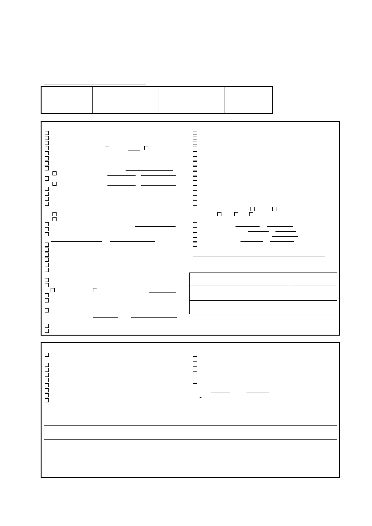
RefNo:
MODEL PRIMARY ID (Port) PRIMARY ID (Starboard) HULL ID NUMBER (HIN)
BOAT MAKER/MODEL IGNITION KEY NUMBER (Port) IGNITION KEY NUMBER (Starboard) TRAILER NUMBER
CHECKBEFOREOPERATION CHECKDURINGOPERATION
All Standard Items Supplied (Defect, Breakage, Missing parts)
Engine Mounting (High, Width, Proper hardware, Secured)
Harness and hoses installation (Secured and Properly Dressed)
Main Wire Harness installation Extended ft No Extended
Multifunction Gage Dip Switch Setting for Application
Instrument Operation/Connections
Tiller Handle Installation/Secure
RemoteControlOperation/Adjustments Type:
CableStrokeandRouting Length: m Min.radius: cm
Shift Throttle Operation
CableStrokeandRouting Length: m Min.radius: cm
MechanicalSteeringOperation/Installation Maker:
HydraulicSteeringOperation/Bleed Maker:
Primer Pump Installed Properly (Arrow pointing up)
Fuel Line/Tank Installation/Connections Routing Sealed/Secured
InnerDiameter: m
Length: m Height: m
BoatFuelFilter Type
FuelVacuumTestResult: kPa@WOT rpm(over 50ps)
BatteryMeets/ExceedsEngineSpecifications Type:
Battery Charged/Secured/Connections Tight
Battery Cable Installation and Routing
BatteryCableType: CableLength:
Battery S/W installation (Secured, Properly Connections)
Manual Tilt Operation
Power Trim/Tilt Operation
Lower Unit Oil Level
Overheat Warning System (Ground sensor lead on applicable models)
Visual Inspection of Engine
<2-Stroke Fuel and Oil Setup>
Break-InPremixRatio(ExceptTLDImodels) 25 : 1
Oil in Remote and Marine Engine Tank
To h a t s u TCW3 EquivalentQualityOilBrand:
Breed Oil Injection Pump / No air oil Injection Lines
Electric Oil Pump Function
<4-Stroke Oil Setup>
Check Engine Oil Level (Ensure unit is not overfilled)
Engine Oil Classification: Brand:
<Carburetion: 2 and 4-Stroke models>
Manual/Electric Choke Operation
Electric Starter Operation (Start in gear protection functions)
Manual/Electric Choke Operation
Neutral Switch function
Stop Switch/Emergency Switch Operation
Steering Operation
Throttle Operation/Friction Adjustment Neutral/Cruising
Proper Shift Cable Adjustment/Operation (F-N-R)
Cooling System Water Flow
Fuel/Oil/Water/Exhaust leaks
Oil Warning system Check (Equipped models)
Indicator Lamp and Buzzer
Oil and Temperature Warning functions (Equipped models)
Engine reaches operating temperature
Power Trim/Tilt Operation
Instrument Operation
Trim Tab Adjustment (retorque after operation)
Propeller Selection: Brand: To h a t s u Other:
Material: SUS AL Plastic
Model: Dia: Pitch:
IdleRPM Single/P: rpm S: rpm
IngearidleRPM Single/P: rpm S: rpm
Factory-recommendedW.O.T.RPMRange: rpm
W.O.T.RPM Single/P: rpm S: rpm
No Cavitations/Ventilation
Remarks:
Inspector’s signature Date
Dealer name Phone number
Dealership address
CUSTOMER DELIVERY CHECKLIST
Operation of Equipment/Boat Accessories Explained
(Proper Trim and Tilt operation demonstrated)
Operation/Orientation Ride with Dealership Personnel
Warranty/Owner’s Manual and Keys Given to Customer by Dealer.
Customer Introduced to Service Manager/Writer
Return-to-Port Operations (Oil System, RPM Reduction)
Gauge Operation/Warning Symbols Explained
2-Stroke: Use of To h a t s u 2 stroke/TC-W3 or Equivalent Rated Oil
4-Stroke: Use of To h a t s u 4 stroke or Equivalent Rated Oil
4-Stroke: Show Customer Proper Checking Procedures and Proper Level of
Engine Oil
Engine Break-in Procedure Explained
Maintenance/Care Schedule Explained
Advised of First Scheduled Maintenance
Warranty Coverage Explained to Customer’s Satisfaction,
Including Customer Responsibilities
Customer questions answered by Dealership Personnel
Break-in Time Placed on Engine by Dealership Personnel
hours: Minutes:
Customer name Phone number
Customer address
Customer signature Date
Date of Issue : / /2007 ORIGINAL TO BE HELD BY DEALER/COPY TO CUSTOMER
TOHATSU OUTBOARD MOTOR
Pre-Delivery Inspection Check List 2 and 4-Stroke Models
The above
materia
l
has been explained and/or provided to me by dealership
p
ersonne
l
.
My questions were answered and explained to my satisfaction.
6
□M70C Maintenance section
Engine
<Disassembly>
Remove each terminal of harness from the power head.
CDI unit harness
Charge coil harness
Ignition coil harness
Lanyard stop switch harness
Each ground wire
Carburetor and throttle linkage connections
Shift linkage connection
Throttle and advance arm connection
Choke linkage connection
7
Fuel hose to fuel filter (In side)
Pilot hose connection
After removing each connection, remove an apron and engine attachment bolts.
Remove carburetors and inlet manifold.
Loose flywheel nut using special tool (Flywheel Puller kit 3C7-72211-1)
Remove flywheel from crankshaft using special tool (Flywheel Puller).
Remove oil re-circulation hose.
Remove, crank case mounting bolts and crankshaft from crankcase.
(Be careful not to damage the piston and piston ring)
8
Check the balance of crankshaft. Crank shaft Deflection Limit: 0.05mm
Inspection of power head cooling water passage
Remove thermostat cover and thermostat.
Remove cylinder head cover and exhaust cover.
Check corrosion and remove clogs and debris from cooling water passage.
Check thermostat, replace if the thermostat valve is open even a little at ambient temperature.
9
Engine
<Assembling>
Assembling engine reverse of their disassemble steps.
*Notes
(1) Install the crankshaft
When install crankshaft ass’y to cylinder, be careful not to apply excessive load to a piston and
a piston ring, and put in a piston in a sleeve.
Check the position of piston ring directions.
Check the dowel pin as allows for positioning upper main bearing.
The crankshaft of an attachment state
Check each position of main bearing and labyrinth packing between #1 and #2 cylinder, #2 and
#3 cylinder.
Size x Q'ty 1 st 2 nd
Cylinder head M8 x 14 1.2-1.5kg.m 3.0-3.5kg.m
Cylinder head cover M6 x 17 0.47-0.64kg.m
Exhaust cover M6 x 14 0.4-0.6kg.m 0.8-1.0kg.m
Intake manihold 0.4-0.6kg.m 0.8-1.0kg.m
Air silencer 0.27-0.36kg.m
8mm 1.2-1.5kg.m 2.4-2.6kg.m
10mm 1.7-2.3kg.m 3.8-4.2kg.m
Flywheel magneto 14.0-16.0kg.m
Carburetor bolt 0.47-0.64kg.m
Crankcase
10
Check the position of lower main bearing located bottom of crankshaft.
Put certainly crankshaft thrust washer in the cylinder grooves.
(2) Apply sealing gasket to crank case
Degrease crank case and cylinder mating faces.
Apply sealing gasket (LOCTITE 518) to crankcase’s mating surface.