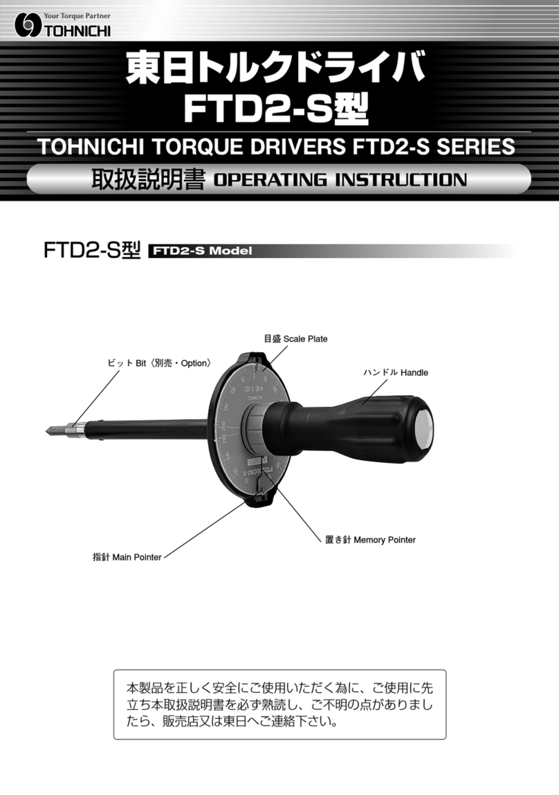
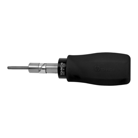
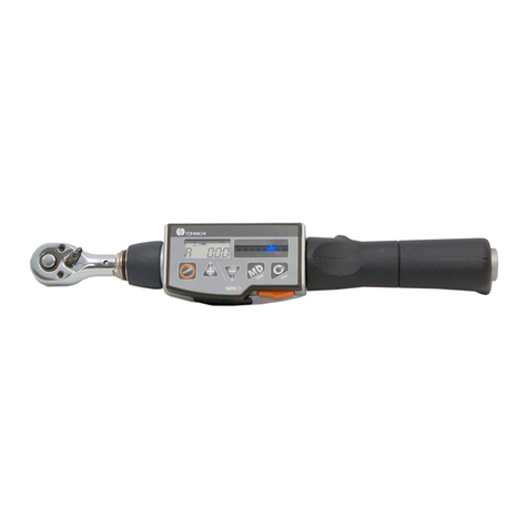
Tohnichi T-BLE User manual

2016/06/14
Solar Powered Wireless Signal
Torque Wrench System
BLseries
Operation Manual
Tohnichi Mfg. Co., Ltd.


1
Safety Precautions
To customers: Before using this product, please read this operating instruction carefully to use it
properly. If you have any question, please contact your nearest distributor or TOHNICHI MFG. CO.,
LTD. This operating instruction should be stored in a safe place.
Signal Words
The signal words are the headers which indicate the level of hazard that should be known for
human safety and in handling devices. The signal words for safety are "Danger", "Warning" and
"Caution" depending on the level of hazard to human. The signal words are used with the safety
symbol to indicate the following situations.
The receiver can be operated only with the power voltage of DC18V to 36V specified in this
operating instruction.
Do not drop water or oil on this instrument. Do not use this instrument in an atmosphere of
flammable gas and steam. Use in such an atmosphere may result in fire.
Avoid shock or vibration to this instrument. It may cause a damage or failure.
Before use, make a pre-operation inspection and check the settings.
Be sure to conduct a periodic inspection of torque wrenches.
Use a torque wrench within the measurement range specified in the operating instruction.
Disconnect from power supply if the product needs to be stored for a long period of time.
Avoid using the instrument in a place where there are metal structures around it.
Avoid using the instrument near welding machines, electric discharge machines or machines
producing electromagnetic noise such as PC.
Before wiring, check power supply off.
Contact your nearest distributor or Tohnichi if any trouble.
Safety Symbol
This symbol is used for drawing attention to "safety precautions". If you see this
symbol in this operating instruction, attention should be paid to safety. Take
preventative actions according to the description and conduct "safety operations
and proper control".
“Danger" Indicates an imminently hazardous situation which, if not avoided, will result in
death or serious injury.
"Warning" Indicates a potentially hazardous situation which, if not avoided, could result
in death or serious injury.
"Caution" Indicates a potentially hazardous situation which, if not avoided, may result in
minor or moderate injury.
Warning

2
INDEX
1 Outline 4
2 Feature 4
3 Components 4
4 Specifications 5
5 External View
5-1 BLE, European and China model 6
5-2 BLA, US model 7
5-3 BL, Japan model 8
5-4 Receiver Display and RS232C 9
5-5 Input and Output terminal 10
6 Preparation for Use
6-1 Solar Cell 11
6-2 Receiver 12
6-3 Antenna 15
6-4 Error on BL receiver 15
6-5 RS232C 16
7 Setting Receiver
7-1 Setting Procedure 17
7-2 Setting Procedure 18
8 Mounting Method of BL transmitter onto LS torque wrench 21
9 Trouble 23
10 Optional Item 23
11 Regulations 24

3
1 Outline
Tohnichi BL series torque wrenches send tightening completion signals by radio waves. The Solar
Panel eliminates need for battery maintenance and costs associated. R-BL receiver models capture
signals from BL wrenches and transfer to external equipment, such as a count checker CNA-4mk3,
Poka-Patrol. The receiver can transfer Completion signals and transmitter serial number to external
equipment. Miss-tightening prevention system can be established with PC or PLC.
2 Feature
•World’s first solar power transmitter
•Create up to 4 contact-free outputs in one receiver
•DC24V power source
•Available AC100V - 240V with optional BA-8 AC adapter
•Upgrading LS type torque wrench to BL type is possible
•Quick communication setting with one click
3 Components
Receiver
Wireless
Wired
PC / PLC
Option
・
RS232C
・
ID/8-digit
Up to 10 torque wrench
Wired

4
4 Specifications
Model T-BLE R-BLE T-BLA R-BLA T-BL R-BL
Description Transmitter Receiver Transmitter Receiver Transmitter Receiver
Frequency 868.3Mhz 902.875Mhz 928.35Mhz
Modulation
System FSK
Rate 125kbps
ID Fixed 8 digit
LED Light #1 LED Light #1 #1
Power Solar Cell DC24V #2 Solar Cell DC24V #2 Solar Cell DC24V #2
Antenna Helix Antenna Dipole
Antenna Whip Antenna Dipole
Antenna Helix Antenna Dipole
Antenna
Temperature 0 – 40 degree Celsius
Distance 10 – 20 m, 30 – 60 feet #3
Wireless
Certificate EU, China USA, Canada Japan
#1 4 Contact Signal Outputs and 6 RS232C Outputs, LAN Output by Request
#2 Connected directly to DC18-36V or with Optional, AC Adapter BA-8, 100 – 240V
#3 Radio frequency communication errors may be caused by electronic noise or a shield placed
between the transmitter and receiver. In addition, radio waves reflected by metal, concrete,
etc. may interfere with radio waves directly sent to the antenna of the receiver and dead
point occurs, resulting in communications errors.

5
5 External View and Each Part Name
5-1 BLE, European and China model

6
5-2 BLA, US model

7
5-3 BL, Japan model

8
5-4 Receiver Display and RS232C
RS232C Pin Assignment
Pin Number Signal Description Direction
1
2 TXD Transmitted Data Signal
3
RXD
Received Data Signal
4
5
GND
Ground
6
7 CTS Clear to Send Signal
8 RTS Request to Send Signal
9
R-BL to PC/PLC
R-BL
PC/PLC D-Sub9S
Pin #
Signal
Description
Pin #
Signal
Description
1
1
DCD
N/A
2
TXD
Transmitted Data Signal
2
TXD
Transmitted Data Signal
3
RXD
Received Data Signal
3
RXD
Received Data Signal
4
4
DTR
N/A
5
GND
Ground
5
GND
Ground
6
6
DSR
N/A
7
CTS
Clear to Send Signal
7
CTS
Clear to Send Signal
8
RTS
Request to Send Signal
8
RTS
Request to Send Signal
9
9
NC
N/A
Frame
Shield
Frame
Shield
Indicating “ID”
Preference on mode setting
Indicating ID # when received signal
Status on mode setting

9
5-5 Input / Output Receiver
Terminal Block
Terminal # Description Features
1 OUT1 Output non-voltage contact signal and LED1 is lit When receiving
completion signal from BL transmitter #1. There is no polarity.
2
3 OUT2 Output non-voltage contact signal and LED2 is lit When receiving
completion signal from BL transmitter #2. There is no polarity.
4
5 RESET Contact terminal to reset “outputting non-voltage contact signal”
and “auto-reset”. Required to input pulse, more than 0.1 second.
6
7 OUT3 Output non-voltage contact signal and LED3 is lit When receiving
completion signal from BL transmitter #3. There is no polarity.
8
9 OUT4 Output non-voltage contact signal and LED4 is lit When receiving
completion signal from BL transmitter #4. There is no polarity.
10
11 LS IN When BL torque wrench is down, LS torque wrench can be wired
to LS-IN and COM for back-up.
12
LED light
LED light

10
6 Precautions for Use
6-1 Solar Cell
Charge the battery before first use and after long periods of nonuse.
BL has available 3000 uses within 8 hours under 500 lux illuminance and 9.6 sec.
communication cycle.
BL can perform 300 uses on a full charge under 0 lux illuminance, No Light Conditions.
A fully charged battery will lose power after approx. 4 days if under no light conditions, 0 lux.
It is recommended to have sufficient light on the line/station to continually recharge the
internal battery cell.
There is no battery level indicator.
Keep the solar panel clean. A dirty panel decreases power generation efficiency.
Do not use a solvent such as paint thinner when you clean up the solar panel.
Recharge to full within 1 and half years even if you do not use BL to prevent the battery from
dying.
Table 1. Measure of the solar cell charging time
Illuminance
lux
Activity Charging time
for available one use
Charging time for fully charge
200 - Approx. 3 min. Approx. 144 hours
500 Standard factory Approx. 1.5 min. Approx. 72 hours
1000 Under 60 to 70 cm
of fluorescent light, 30W Approx. 44 sec. Approx. 35 hours
2000 Under 40 cm
of fluorescent light, 30W Approx. 22 sec. Approx. 17 hours
1 Above table is an estimate only. It is when BL is being charged under continuous light conditions.
2 BL charges as you are using it, therefore it is not a requirement for to have a fully charged battery
before use.
Table 2. Measure of illuminance by the available uses
Illuminance
lux
No pre-charge 30 min. pre-charge 1 hour pre-charge
Available
Uses
Communication
Cycle /s
Available
Uses
Communication
Cycle/s
Available
Uses
Communication
Cycle/s
200 1500 19.2 1594 18.1 1688 17.1
500 3000 9.6 3188 9.0 3375 8.5
1000 6140 4.7 6524 4.4 6908 4.2
2000 12278 2.3 13045 2.2 13813 2.1
3 Available uses means when BLA is charged under continuous light under each level of illuminance, lux.
4 "No pre-charge" not include the time of available one use on Table 1.
5 "Communication cycle" means 8 hours, 28,800 sec. divided by available uses.

11
6-2 R-BL, Receiver
a Power Source
Use the Receiver R-BLA within the range of DC24V.
Make sure to connect DC24V and GND to respective terminal.
The tightening torque of the terminal block is T=50cN.m.
b Operating environment
Use the device in an environment where no metal structure exits nearby wherever possible.
Do not set the antenna for the receiver close to any metal pole, wire or iron pipe. The BL
receiver antenna is arranged parallel to pipes, the communication status may be worsened.
Do not use the device around welding machines, electric discharge machines or any machine
producing electromagnetic noise such as PC.
c Connection with other equipment
Before wiring, check that the power of the device to be connected with the receiver is in the
OFF position.
Use a solder-less terminal of the size as shown below.
The tightening torque of the terminal block screw is T=50cN.m.
5.8mm or less
5.8mm or less
R-BL, Receiver
GND
DC24V

12
d Connecting “RESET”and “LS IN”
If you would like to connect to the "RESET" and "LS IN" terminal please use a non-contact
voltage switch. Example, LS torque wrench, relay, etc.
Do not feed the external power to input circuit to prevent damage.
EMI filter
EMI filter
Internal circuit
RESET
Vcc
LS-IN
Photocouple
r
Photocoupler Non-voltage
contact switch
Non-voltage
contact switch
e Relay output from OUT1, OUT2, OUT3 and OUT4.
Relay
Relay
Internal circuit
OUT
1
OUT
4
Load
External power
Load
External power
・・・・
Set the load of the contact output within the rated load. Relay output rating: DC30V 1A, AC125V
0.5A. The above rated contact capacity is according to resistance load. Some kinds of loads have a
big difference between the steady-state current and the inrush current. Typical loads and inrush
currents are as follows:
Kind of Load Inrush Current
Resistive Load
1 time as large as the steady-state current
Solenoid Load
10 to 20 times as large as the steady-state current
Motor Load
5 to 10 times as large as the steady-state current
Incahdescent Lamp
10 to 15 times as large as the steady-state current
Mecury Vapor Lamp
About 3 times as large as the steady-state current
Sodium Vapor Lamp
1 to 3 times as large as the steady-state current
Capacitor Load
20 to 40 times as large as the steady-state current
Trans Load
5 to 15 times as large as the steady-state current

13
f Contact Protection Circuit
When the inductive load is opened or closed, a counter-electromotive voltage is generated
and causes a heavy damage to the contact, resulting in a significant shortening of operating
life. Therefore, a contact protection circuit is required. The examples of contact protection
circuits are as shown in the table below.
AC DC
If this circuit is used for timer
loads, leakage current flowing
through cr cause faulty operation.
*If used with AC voltage,
impedance of the load should be
○ ○
D
i
o
d
e
t
y
p
e
×
○
Energy stored in the coil is
discharged to the coil by flow of
current by the diode connected in
parallel to the load and is
consumed by joule heat of the
resistance of the inductive
Use a diode with a peak inverse
voltage 10 times higher than the
circuit voltage and a forward current
as high as or higher than the load
current. In an electronic circuit
where the circuit voltage is not so
high, a diode with a peak inverse
voltage about 2 to 3 times higher
Selection of element
Circuit example
C
R
t
y
p
e
※
△
○
The standard c and r are as follows:
c:0.5 to 1 (μF) per contact current
(1A)
r:0.5 to 1(Ω) per contact vaolage
(1V)
The above values vary depending on
the property of load or variations in
relay characteristic. Considering that
the capacitor "c" has the effect of
controlling the discharge when the
contactes are open and the resistor
"r" plays the role fo controlling the
current at the next power-on, check
through experiments is required.
Normally, use a capacitor with a
If the load is a relay or solenoid, the
reset time is delayed. It is effective
to connect between the loads when
the power supply voltage is 24 or
48V and to connect between the
contacts when the power supply
voltage is 100 to 200V
Applicability
Features/others
rc
Relay contact
I
n
d
u
c
t
i
v
e
l
o
a
d
r
c
Relay contact
I
n
d
u
c
t
i
v
e
l
o
a
d
Relay contact
Diode
In
d
u
c
tiv
e
lo
a
d

14
6-3 BL Antenna
Refer to below drawing when mounting or dismounting an antenna on R-BL receiver. Do not
turn antenna itself. Hold the antenna and turn the notched end of the antenna.
6-4 Error on R-BL receiver
When following Error codes are indicated on R-BL receiver, cancel each error condition.
Code Description Solution
ERR6 Flow Control Error
CTS, Clear to Send signal is undetected.
Make sure CTS/RTS flow control.
Check if the connector cable is properly connected.
ERR8 Memory Abnormality Memory data is defected. Reset all.
Contact Tohnichi for repairing.
ERR13 Overlapping The ID has been registered to a different output already.
Remove it and register again.
Hold the antenna not to rotate
Rotate the jagged part

15
6-5 RS232C
Description
Factory Default
Baud Rate
Selectable 2400/4800/9600/19200/38400/115200bps
115200bps
Parity
Selectable None/Even/Odd
None
Data Length
Selectable 7 or 8 bit
8bit
Stop Bit Selectable 1 or 2 bit 1bit
Flow Control
Selectable ON/OFF, CTS-RTS
off
Output Format, non registered ID
R E , * * * * * * * * CR LF
Output Format, registered OUT1 to 4
R E , * * * * * * * * , O U T * CR LF
Output Format, registered RS1 to 6
R E , * * * * * * * * , R S * CR LF
Output Format when input LS-IN
R E CR LF
Reset Command Format
A T 1 3 0 CR LF
Input Contact terminal to reset “outputting non-voltage contact signal” and “auto-reset”.

16
7 Setting Receiver
7-1 Setting Receiver
As a default setting, BL Receiver receives all signals of BL Transmitter, T-BLA to R-BLA, T-BLE to
R-BLE and T-BL to R-BL. Refer to 7-2, Setting Procedure. ID registered receiver does not receive any
other ID signal. Up to 10 Transmitters can be registered to one receiver. Total 4 IDs output as
non-voltage contact signal and RS232C output. Other 6 IDs output through RS232C only.
OUT1 to OUT4 Register IDs on OUT1 to OUT4
OUT1 to OUT4 outputs ID through contact output and RS232C.
RS1 to RS6 Register IDs on RS1 to RS6
RS1 to RS6 outputs ID through RS232C
Flow Control Select ON/OFF of CTS, RTS control
Baud Rate Select one from 2400, 4800, 9600, 19200, 38400, and 115200bps
Parity Select one from NONE, ODD, and EVEN
Data Length Select one between 7 and 8bit
Stop Bit Select one between 1 and 2bit
Buzzer Sound Select ON/OFF of buzzer sound
Auto Reset Timer Select between 0.0~9.9 seconds
Since R-BL does not receive any signal during the auto reset process, this
function also can be used as double count prevention
Auto reset function will be disabled if set as 0.0 second. In this case, reset can be done only
through reset input or through reset command.
Factory Default
Item
OUT1
to
OUT4
RS1
To
RS6
Flow
Control Baud Rate Parity Data
Length Stop Bit Buzzer
Auto
Reset
Timer
Status Off 115200bps NONE 8bit 1bit ON 0.1 Sec

17
7-2 Setting Procedure
Turn on the power switch while pressing SET key to start mode setting.
Status lamp flashes red and blue when you are in Mode Setting.
In Mode Setting, select BL preference by press “SET” key, from OUT1 to the End.
OUT1-OUT2-OUT3-OUT4-RS1-RS2-RS3-RS4-RS5-RS6-Flow-Baud-Parity-Length-Stop-Buzz-Auto-End
Setting OUT1 to OUT4
“ - - - - -“ is displayed on status screen when no tool is
registered.
Registered 8 digit number of Transmitter ID is displayed.
Select Switch
Set Switch
Power Switch

18
Press The “SELECT” key to choose between “ENTRY”or
“CLEAR”. Select “ENTRY” by pressing the “SET” key.
“READY” appears on screen. Status lamp blinks in red.
Operate BL transmitter and the receiver receives ID. The
registered ID number is displayed on status screen.
To cancel any registered ID, press SELECT key and choose
“CLEAR” and press the SET key.
Setting RS1 to S6
Press “SET” key to register the next tool.
After making a selection, press the “SET” key to go to the
next screen.
Setting Flow Control
Press SELECT key to select ON/OFF of Flow Control.
Setting Baud Rate
Press SELECT key to select a Baud Rate from 2400, 4800,
9600, 19200, 38400, and 115200bps.
This manual suits for next models
5
Table of contents
Other Tohnichi Tools manuals
Popular Tools manuals by other brands

Humboldt
Humboldt H-4137 instruction manual

Sears
Sears CRAFTSMAN WOODWORKERS VISE 391.5195 owner's manual
U-Line
U-Line H-8073 quick start guide
SKF
SKF TMHP 15 Series Instructions for use
DR Power Equipment
DR Power Equipment PTO POST HOLE DIGGER Safety & Operating Instructions
Launch
Launch Creader Elite GM troubleshooting guide
