Tohnichi ProTork CPT20X10D-G User manual

TOHNICHI DIGITAL TORQUE WRENCH FOR TIGHTENING
MODEL CPT-G
To use this product correctly and safely, please read this manual carefully before use.
If you have any questions about the product, contact your nearest distributor or TOHNICHI MFG. CO., LTD.
CPT20X10D-G
CPT100X15D-G
CPT280X22D-G
OPERATING INSTRUCTION
To the user
In order to use the torque wrench properly and safely, please read this instructions before operation. If any question,
please contact a Tohnichi ofcial distributor or Tohnichi ofce. Keep this operating instruction for future use.
Signal Words
Signal word is the title which shows the item which should be known on safe reservation of people and the handling of
equipment. The signal word on safe has the classication of "danger", "warning" and "cautions" by the degree of riskof doing
to people. It uses with a safe cautions symbol and the following situation is shown, respectively.
①Please pay attention to the surrounding conditions or environment.
Do not use the main wrench, the charger and the battery in rain, or at wet condition.
It may cause an electric shock or re.
Keep the work place well lit to avoid accidents.
Using it in a dark place may cause accidents.
Do not use in a place where inammable liquid and gas exist.It may cause explosion or re.
② Use the designated accessories only.
Do not use any items not directed in this instruction manual. It may cause explosion or injuries.
① Keep the working place clean and tidy.
Working in a messy condition may cause accidents.
② Keep children away from the product or the work place.
As a basic rule, do not let any other person than the user himself should touch the product. It may cause injuries.
③ When not in use, keep them in a safe place.
Storage place should be in dry condition where it is securely locked and away from children. Otherwise, it may cause
injuries.
Do not keep the main wrench or the battery in a environment where the temperature may exceed 50 degree Celcius.
It may lead to deterioration of the battery and cause re.
④ Do not force this product to use beyond its capacity.
In order to use it safely and efciently, use this product within the designated torque range. Using the product beyond its
capacity may cause accidents.
⑤ Use this product to t work.
Do not use this product for any other purpose than the instructed usage..It may cause injuries.
⑥Always brace yourself and maintain balance when working.
Be careful not to slip and fall, which may cause injuries.
⑦ Do maintenance work carefully.
Keep the handle part of the wrench clean and dry. Keep it from oil or grease. Otherwise, it may cause the handle to slip
and lead to injuries.
⑧ Conduct periodic checking to detect damaged part.
If you nd any damaged part such as the plug or cord, request repair or replacement to the authorized distributor or
Tohnichi. If you keep using the damaged ones, it may cause short-circuit or re.
Warnings
!
Cautions
!
The safety alert symbol
This symbol means Attention! Your safety is involved.
Take prevention measures in this manual and performing "safety use and appropriate management".
!
" Danger" :Imminent danger acting as a serious obstacle.
" Warnings" :A potential risk of becoming a serious obstacle.
" Cautions":A potential risk of becoming an obstacle although
it does not result seriously.
!
!
!
2
Cautions on Safety

(1) Use the instructed batteries only.
(2) Do not apply vibration or physical impact on the product.
(3) Use this product only in conditions instructed on this manual.
(4) Check the functions and settings before use.
(5) Do not put the product in water or oil as it may cause product failure.
(6) Do not drop or hit the product against wall as it may cause breakage.
(7) Use the product within its capacity instructed in the manual.
(8) Make sure to conduct periodic check on the product.
(9) Check the display shows 0 before measuring.
(10) For accurate tightening or measuring, make sure to grip on the effective length line rmly and apply force at a right
angle.
If the product should catch re or emit unusual smell, stop using the product immediately, and put it in a safe place. Contact
TOHNICHI MFG. CO., LTD. for further instructions.
3
Precautions for Use

1. Outline ・・・・・・・・・・・・・・・・・・・・・・・・・・・・・・・・・・・・・・・・・・・5
2. Features ・・・・・・・・・・・・・・・・・・・・・・・・・・・・・・・・・・・・・・・・・・5
3. Components ・・・・・・・・・・・・・・・・・・・・・・・・・・・・・・・・・・・・・・・ ・5
4. Name and Explanation of Each Part ・・・・・・・・・・・・・・・・・・・・・・・・・・・・・・6
5. Explanation of Functions ・・・・・・・・・・・・・・・・・・・・・・・・・・・・・・・・・・・7
① Auto Zero function ・・・・・・・・・・・・・・・・・・・・・・・・・・・・・・・・・・・・・・7
② Auto Memory/Reset ・・・・・・・・・・・・・・・・・・・・・・・・・・・・・・・・・・・・・7
③ Mute ・・・・・・・・・・・・・・・・・・・・・・・・・・・・・・・・・・・・・・・・・・・・7
④ Auto Power off ・・・・・・・・・・・・・・・・・・・・・・・・・・・・・・・・・・・・・・・7
⑤ Residual battery display ・・・・・・・・・・・・・・・・・・・・・・・・・・・・・・・・・・・7
⑥ Over torque alarm ・・・・・・・・・・・・・・・・・・・・・・・・・・・・・・・・・・・・・・7
⑦ Over torque alarm/Peak Hold starting torque ・・・・・・・・・・・・・・・・・・・・・・・・・・7
6. Explanation of Each Mode ・・・・・・・・・・・・・・・・・・・・・・・・・・・・・・・・・・8
7. How to Use ・・・・・・・・・・・・・・・・・・・・・・・・・・・・・・・・・・・・・・・・・8
① Preset tightening mode ・・・・・・・・・・・・・・・・・・・・・・・・・・・・・・・・・・・8
② Judgement tightening mode ・・・・・・・・・・・・・・・・・・・・・・・・・・・・・・・・・10
③ Saving measured data ・・・・・・・・・・・・・・・・・・・・・・・・・・・・・・・・・・・11
④ Reading out data ・・・・・・・・・・・・・・・・・・・・・・・・・・・・・・・・・・・・・・11
⑤ Output of the measured data ・・・・・・・・・・・・・・・・・・・・・・・・・・・・・・・・・12
⑥ Deleting measured data ・・・・・・・・・・・・・・・・・・・・・・・・・・・・・・・・・・・12
⑦ Inspection use by Re-tightening torque method/Loosening torque method ・ ・ ・ ・ ・ ・ ・ ・ ・ ・ ・ ・ ・ 13
8. Various Settings ・・・・・・・・・・・・・・・・・・・・・・・・・・・・・・・・・・・・・・14
① Settings ・・・・・・・・・・・・・・・・・・・・・・・・・・・・・・・・・・・・・・・・・・14
② Flow chart on settings ・・・・・・・・・・・・・・・・・・・・・・・・・・・・・・・・・・・・14
③ Setting on Preset tightening mode ・・・・・・・・・・・・・・・・・・・・・・・・・・・・・・15
④ Setting on Judgement tightening mode ・・・・・・・・・・・・・・・・・・・・・・・・・・・・16
⑤ Other settings ・・・・・・・・・・・・・・・・・・・・・・・・・・・・・・・・・・・・・・・18
9. External Output ・・・・・・・・・・・・・・・・・・・・・・・・・・・・・・・・・・・・・・・20
10. Battery ・・・・・・・・・・・・・・・・・・・・・・・・・・・・・・・・・・・・・・・・・・20
11. Error Message ・・・・・・・・・・・・・・・・・・・・・・・・・・・・・・・・・・・・・・・21
12. Specications ・・・・・・・・・・・・・・・・・・・・・・・・・・・・・・・・・・・・・・・22
4
Contents

This product is a digital torque wrench for tightening purpose. Upon reaching the set torque, a buzzer goes off and LED
turns on to signal tightening completion. Applied torque will be indicated on the digital display as well as on LED indicator.
・The indicator display enables the user to see the setting torque and the actual torque being applied at the same time.
・Applied torque will be directly reected on the display in a timely fashion.
・Can register maximum 10 different torque settings (Target torque/Upper limit value/Lower limit value).
・Multiple units of measure selection through keypad setup: N
・
m, kgf
・
cm,kgf
・
m,lbf
・
in,lbf
・
ft.
・Maximum 50 of tightening data can be stored in the internal memory, and transferred to PC with RS232C cable (Optional).
・AA batteries are used (available in the local market).
・Can be used for re-tightening inspection method as well as loosening torque inspection method.
1) Main body ・・・・・・・・・ ・ ・ 1pc
2) Operating Instruction ・・・・・・・1pc
Only for "-SET" model version
3) AA batteries ・・・・・・・・・・2pc
4) Interchangeable head "TQH" ・・・1pc
5) Storage case ・・・・・・・・・・1pc
Optional Accessories
・PC connecting cable (No.585)
・Data processing software (EXCEL RECEIVER)
Cautions)
The interchangeable head (TQH) included in "-SET" model version does not guarantee its durability for specic continuous
number of use, etc. Use it only with a CPT torque wrench, otherwise the product may not maintain the original durability. In
case of breakage,
Tohnichi will be able to replace it with a new one (at your cost). Repairing may not be acceptable.
5
1.Outline
2.Features
3. Components

6
① LCD display
Torque value, memory counter, tightening mode, torque unit, residual battery level will be indicated.
② Indicator display
Applied torque will be indicated by red and blue LED lamp positioning.
③ POWER key
Turn on/off power.
④ ▲ key
Send the counter forward and displays the measured data if any.
⑤ ▼ key
Send the counter backward and displays the measured data if any.
⑥ MD key
Push this key in PEAK mode, then it proceeds to "selecting the setting torque"
When you keep it pushed, it proceeds to "all data deletion" When you keep it pushed in RUN mode, it proceeds to
"settings"
⑦ MEM key
Push this key to save the measured data send forward the counter.
⑧ C key
Measured data will be cleared.
⑨ Handle
AA batteries x 2pc are to be set inside the handle.
⑩ Cap
Cap for battery replacement (counter-clockwise)
⑪ Reset switch
In case of display error or operational error, push this to reset. Noneed to use this switch after every recharging.
⑫ External output terminal
Connect the communication cable (No.585) to this terminal.
①②
⑥
⑨⑩
③ ④ ⑤⑦ ⑧
Set Torque Memory
(Not displayed on Run measuring mode.)
《LCD Display Details》
Torque Unit
J 01
A 100.0
N・m
-
Memory Counter
Displayed Torque
Tightening mode display
※ There will be no alphabetical symbol on LCD in Preset tightening mode. Only in Tightening judgement mode,
"J" appears on the upper left side of the LCD.
Tightening direction display will be indicated only in case of counter clockwise direction as "-", otherwise the
direction is clockwise.
Residual battery display
Tightening direction display
4. Name and Explanation of Each Part
⑪
⑫

① Auto Zero function
In RUN mode, push Clear key to activate Auto Zero function. Displayed torque value will be cleared to zero (Auto Zero
function will activate only when the displayed torque is within 7.5% of the maximum torque value). If the value is 7.5% of
the maximum torque or more, it may show "Err9". Please refer to P25 "Error Message" for details.
② Auto Memory/Reset
Tightened torque value will be stored in the internal memory automatically after the set timing (selectable between 0.1 – 5
seconds) and the counter will be forwarded to the next. When the communication cable (No.585) is connected to CPT, torque
data will automatically be output through the cable as auto memory saves the torque value. If you do not need to activate Auto
Memory/Reset, set it at 0.0 second.
Auto memory/reset will be activated only when the torque reaches beyond the lower limit value. Also, if the target torque
or upper/lower torque limit is set as Zero values, this function will not be active.
③ Mute
Set "OFF" on Buzzer setting. Buzzer will not go off.
④ Auto Power off
Power will be automatically turned off after 3 minutes without any key operation or any torque load (7.5% or lower of the
maximum torque capacity).
In case of "LoBATT" alarm (low battery) condition, it turns off after 1 minute without use.
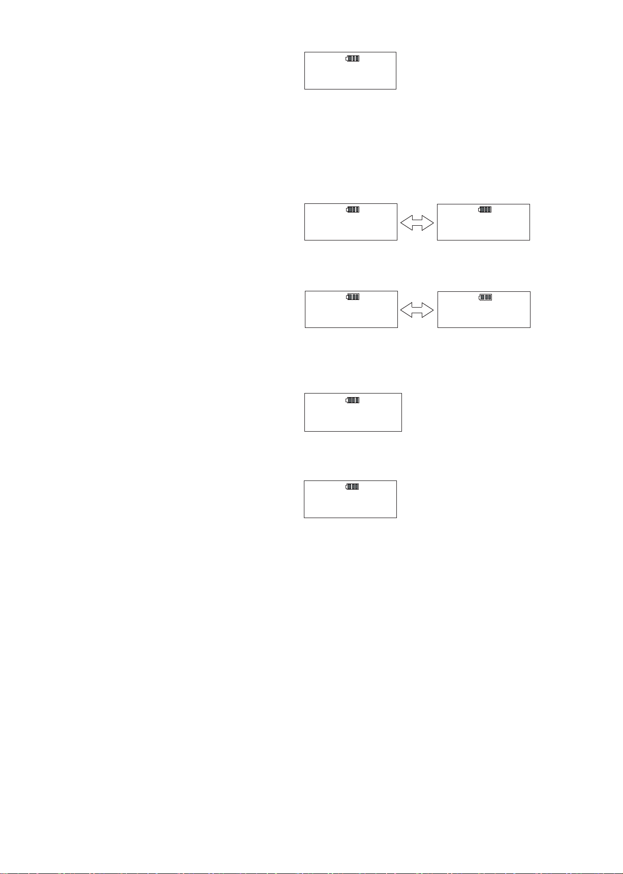
⑤ Residual battery display
It indicates the residual battery amount by LCD indicator.
⑥ Over torque alarm
When the applied torque exceeds 105% of the maximum torque capacity, the display blinks between " ---- " and the
torque value and the buzzer goes off. In this case, the measured data will not be saved by the manual operation.
⑦ Over torque alarm/Peak Hold starting torque (Unit: N
・
m)
7
Blinking
Enough battery power remains.
About half the battery power is gone.
Prepare to replace the new batteries.
"LoBATT" alarm
No battery left. Please immediately replace
the new batteries.
When "LoBAT T " appears, all the keys
operation will be ineffective except the power
switch. After 1 minute, it turns off. The setting
and the saved data will remain after batteries
are gone.
5. Explanation of Functions
105% of Max. Torque 7.5% of Max. Torque Indication Start Torque
Min. Max. Over Torque Alarm Peak Hold Start Torque 20 digit
CPT20X10D-G 4 20 0.02 21.00 1.50 0.40
CPT50X12D-G 10 50 0.05 52.50 3.75 1.00
CPT100X15D-G 20 100 0.1 105.0 7.5 2.0
CPT200X19D-G 40 200 0.2 210.0 15.0 4.0
CPT280X22D-G 56 280 0.2 294.0 21.0 4.0
Model Torque Range 1digit Below 7.5% of Max. Torque
Auto Zero Range
1.50
3.75
7.5
15.0
21.0
※ All the units except N.m, calculate the torque value based on the unit conversion table on P18.

① Preset tightening mode "PRESET" (default)
Set the target torque and range,and tighten up to that torque.
Set the tightening mode to "PRESET" (default).
This mode is for simple tightening operation that does not require a judgement or recognition of tightening direction.
Blue LED shows the target torque range.
(Please refer to P19 for setting procedures.)
Example)
When you set target torque 100N
・
m and target range 5%, then the blue LED blinks in the range of 100-105N
・
m
.
○ Selecting the target torque
PEAK mode (set the memory counter to 01-50).
Press MD key to proceed to torque setting.
Use ▲▼ key to select pre-registered torque value and
press MEM key to conrm.
When there is measured data remained in the memory,
you cannot change torque setting.
Please clear the measured data before change.
Press MD key or C key to proceed to measuring mode without changing the torque setting.
① Continuous display (RUN mode)
Set the memory counter to "00". The applied torque will be directly displayed without peak holding, and torque value will
be returned to zero as you release loading.
Indicator display will not be used.
② Maximum value display (PEAK mode)
Set the memory counter between "01 – 50". Displayed value will increase as torque is applied, and captures the
maximum value (PEAK torque) and remain displayed even after releasing loading. The indicator display will also be held
at PEAK value.
(Please refer to P16 for operating instructions)
③ Tightening mode
PEAK mode has two different tightening settings.
Both tightening modes can register up to 10 different torque values A through J (target/upper/lower torque value).
・Preset tightening mode “PRESET” (default)
Use it as adjustable style of torque wrenches. First, set the target torque and target range (%). As you apply torque, the
red LED starts to blink and move toward right. When it reaches the target range, the blue LED starts to blink and the
buzzer goes off. When it reaches out of the target range, the red LED starts to blink and a buzzer goes off-and-on for
alarm to prevent over-torque.
(Please refer to P10 for operating instructions and P19 for setting procedures.)
・Judgement Tightening mode "JUDGE"
A judgement will be given after tightening.
Set the lower limit torque, and the upper limit torque, and the judgement will be given after tightening. As torque is
applied, the red LED indicator starts to blink and moves toward right. Upon reaching the lower limit torque, the blue LED
blinks and the buzzer goes off to signal completion. When it exceeds the upper limit, the red LED starts to blink again and
another buzzer goes off for alarm.
(Please refer to P12 for operating instructions and P21 for setting procedures.)
8
6. Explanation of Each Mode
----
.
N・m
A
100 0
----
.
N・m
B
120 0
Blinking
Blinking
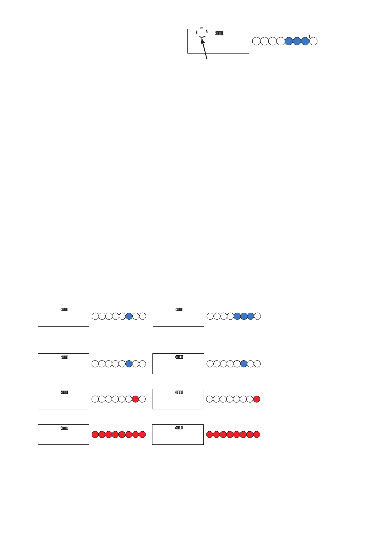
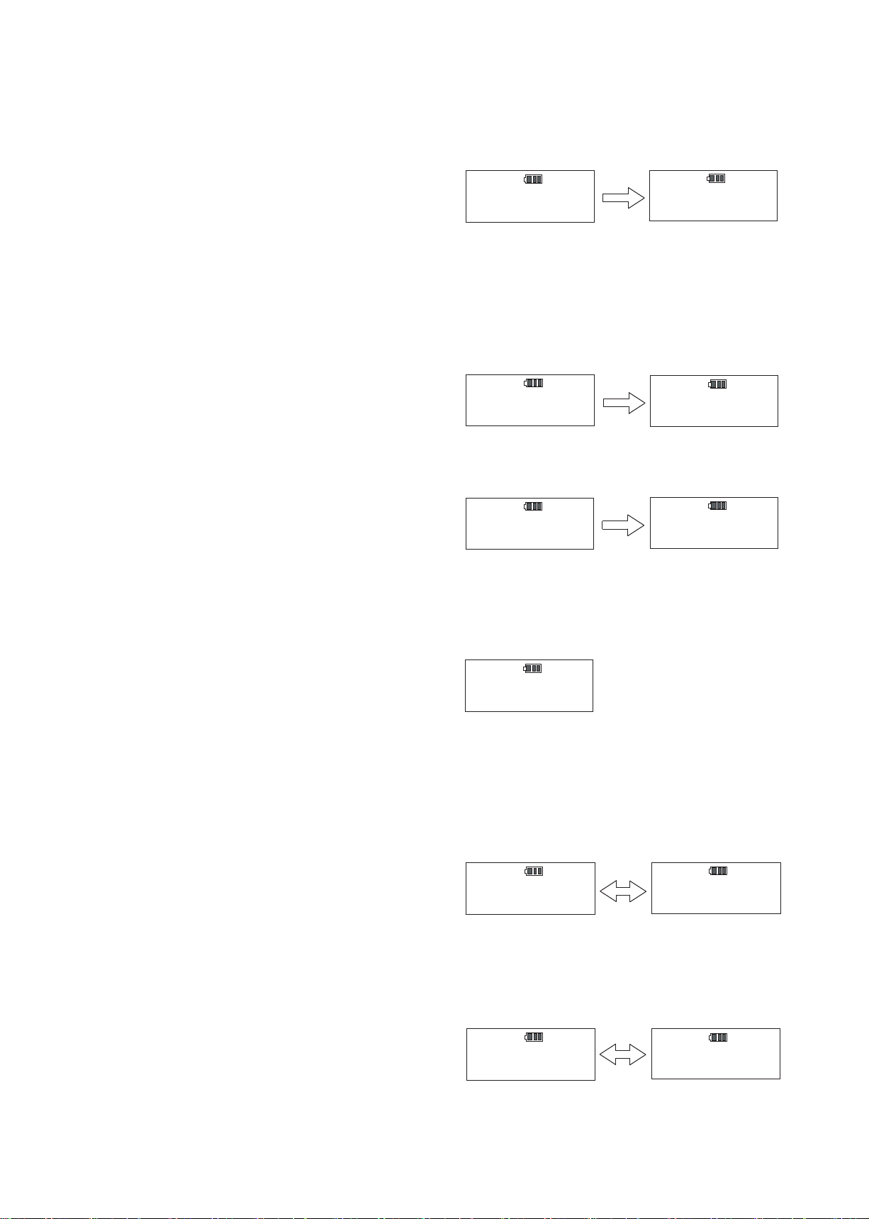
7. How to Use

Tightening operation
Example)Target torque: 100N
・
m
Target range :5%
Blue LED turns on to indicate the target torque.
Start tightening
When it reaches 20% of the target torque, red LED
turns on. (Red LED may turn on at 7.5% of the max
capacity torque in case 20% of the target torque is
higher than this value.)
As torque increases, the red LED moves toward right.
When it reaches 80% of the target torque value, buzzer
starts to sound off-and-on (slow pace) to indicate the
target torque is near.
When it reaches the target torque range, the blue LED
starts to blink and the buzzer goes off continuously to
inform tightening completion.
If it exceeds the target range, the red LED turns on
again, and the buzzer pattern turns to off-and-on (fast
pace).
Press MEM key to save and proceed to the next
counter. If you need to clear the data, press C key.
※ It does not give a judgement.
Example)Target torque: 0 N
・
m
Blue LED at the target torque part will NOT turn on.
When it reaches 7.5% of the maximum torque capacity,
the blue LED turns on and starts to move toward right.
01
0.0
N・m
A
Blue
01
20.0
N・m
A
Blue
Red
01
50.0
N・m
A
Blue
Red
01
80.0
N・m
A
Red
Blue
01
100.0
N・m
A
Blue Blinking
01
110.0
N・m
A
Red
9
02
0.0
N・m
A
Blue
Proceed to the next counter
○

② Judgement tightening mode "JUDGE"
This mode is for tightening with a judgement function.
Set the tightening mode to "JUDGE".
Set the target torque range (lower limit value and the upper limit value) and tightening direction. A judgement will be given
as you press MEM key after tightening (In Auto memory/reset mode, the judgement will be given automatically).
If you apply torque in the opposite direction against the settings, Peak Hold function will be ineffective.
(Please refer to P21 for setting procedures.)
Selecting the target torque
PEAK mode (set the memory counter to 01 – 50).
Push MD key to proceed to torque setting.
Use ▲▼ key to select pre-registered torque value and press MEM key to conrm.
When there is measured data remained in the memory, you cannot change torque setting. Please clear the measured
data before change.
Press MD key or C key to proceed to measuring mode without changing the torque setting.
110.0
100.0
N・m
A
130.0
120.0
N・m
B
Lower limit value
Upper limit value Blinking
Blinking
10
Tightening operation
Example)Lower limit value: 80N
・
m
Upper limit value: 100N
・
m
Tightening dorection: CW
Start tightening
When it reaches 20% of the lower limit value, red LED
turns on.(Red LED may turn on at 7.5% of the max
capacity torque in case 20% of the target torque is
higher than this value.)
As torque increases, the red LED moves to right. Upon
reaching the 80% the buzzer starts to sound off-and-on
(slow pace) to indicate the lower limit value is near.
Upon reaching the lower limit value, blue LED turns
on and the buzzer changes to continuous pattern to
signal tightening completion.
If it exceeds the upper limit value, the red LED turns on
again, and the buzzer pattern turns to off-and-on (fast
pace).
J 01
0.0
N・m
A
Blue
J 01
20.0
N・m
A
Red
Blue
J 01
64.0
N・m
A
Red
Blue
J 01
80.0
N・m
A
Blue Blinking
Blue
J 01
130.0
N・m
A
Red
Blue
○
○
Press MEM key again to save the measured data and proceed to the next counter.
Press C key to clear the data.
※Peak Hold function will be ineffective when you tighten in the opposite direction.
Example)Lower limit value: 0 N
・
m
Blue LED at the target torque part will NOT turns on.
When it reaches 7.5% of the maximum torque capacity, the blue LED turns on and starts to move toward right.
Press MEM key to judge if the tightened torque value
is within the target range (In Auto Memory/Reset mode,
judgement will be given automatically).
・OK: Measured data will be saved and proceed to the
next counter.
・NG: Buzzer goes off and the red LED turns on for
alarm.
11
J 02
0.0
N・m
A
Blue
Proceed to the next counter
③ Saving measured data
Measured data will be saved up to 50.
●Preset Tightening Mode:
Press MEM key, then the measured data will be saved and the counter will be forwarded to the next (In Auto
memory/Reset mode, it will be forwarded automatically).
●Judgement Tightening mode
Press MEM key, then a judgement will be given (In Auto memory/Reset mode, judgement will be given automatically).
If the judgement is OK, the measured data will be saved and counter will be forwarded to the next.
If the judgement is NG, buzzer goes off. Press MEM key again to save the measured data, or Press C key to clear the
data.
※Tightened torque data will not be saved in case of over-torque tightening (tightening beyond its capacity).
※ Auto memory/reset will be activated only when the torque reaches beyond the lower limit value. Also, if the target torque
or upper/lower torque limit is set as Zero values, this function will not be active.
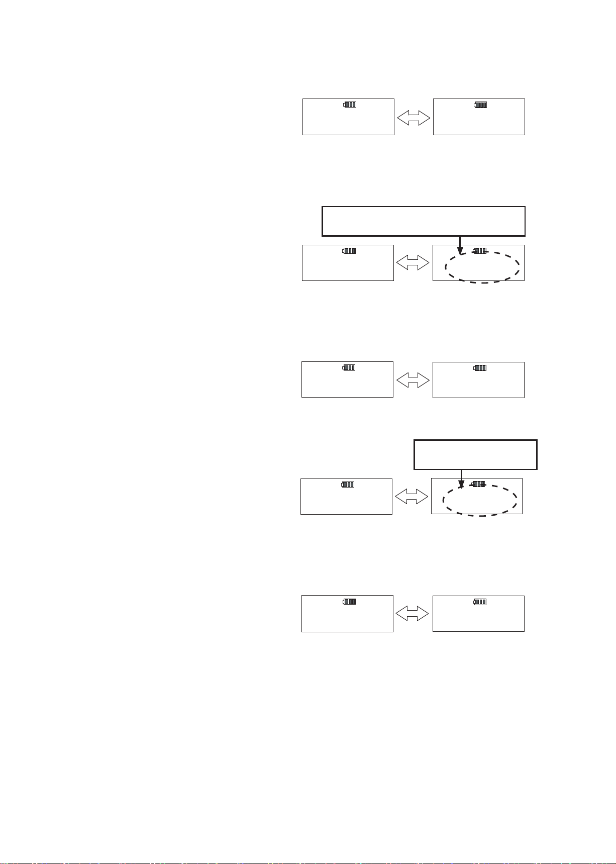
④ Reading out data
Press ▲ key to proceed to the next counter, press ▼ key to read out the measured data.
・In case of OK judgement
・In case of NG judgement
・In case the measured torque is beyond 105% of the max torque capacity of the torque wrench.
If you press ▼ key when the counter shows 01, it becomes 00 and enter RUN mode.
If you press ▼ key again when the counter is 00, the counter changes to 50 and reads out the measured data of that
counter.
11
0.0
N・m
A
J 11
0.0
N・m
A
BlueBlue
10
100.0
N・m
A
J 10
100.0
N・m
A
BlueBlue
10
110.0
N・m
A
J 10
110.0
N・m
A
RedRed
・ Preset tightening mode ・ Judgment tightening mode
10
---.-
N・m
A
J 10
---.-
N・m
A
RedRed

12
Blinking
⑤ Output of the measured data
●Outputting one data
To output the measured data to PC, connect CPT to PC with the communication cable (No 585). Use ▲ ▼ key to select
the data and press MEM key.
●Outputting selected range of data
To output a selected range of data at one time, connect CPT to PC with the communication cable (No 585). Set the
counter to the upper end of the selected range.
Keep MD key pressed for 2 seconds or more seconds, then it proceeds to below display.
Use ▲▼ key to set the counter to the lower end of the selected range of data and press MD key. The display shows the
number of the selected data (Press C key to cancel).
Press MEM key to output the selected data at one time. Press C key to cancel and return to measuring mode.
After outputting the data, the display returns to the number of data to output. Press C key to return to measuring mode.
Press MEM key to output the data again.
⑥ Deleting measured data
●Deleting one of data
To delete one of data, press ▲▼ key to select the data to delete, and press C key to delete it.
●Deleting selected range of data
To delete a range of data, please follow instructions below.
Use ▲▼ key to select the upper end of the data to delete.
Keep MD key pressed for 2 seconds or more seconds, then it proceeds to below display.
・Preset tightening mode ・Judgement tightening mode
10
STT 1
N・m J 10
STT 1
N・m
Memory Counter Lower
10
100.0
N・m
A
J 10
100.0
N・m
A
Memory Counter Upper Memory Counter Upper
n
10
N・m n
10
N・m
Number of data to output
・Preset tightening mode ・Judgement tightening mode
10
100.0
N・m
A
J 10
100.0
N・m
A
Memory Counter Upper
Memory Counter Upper
10
STT 1
N・m J 10
STT 1
N・m
Memory Counter Lower
10
100.0
N・m
A
J 10
100.0
N・m
A
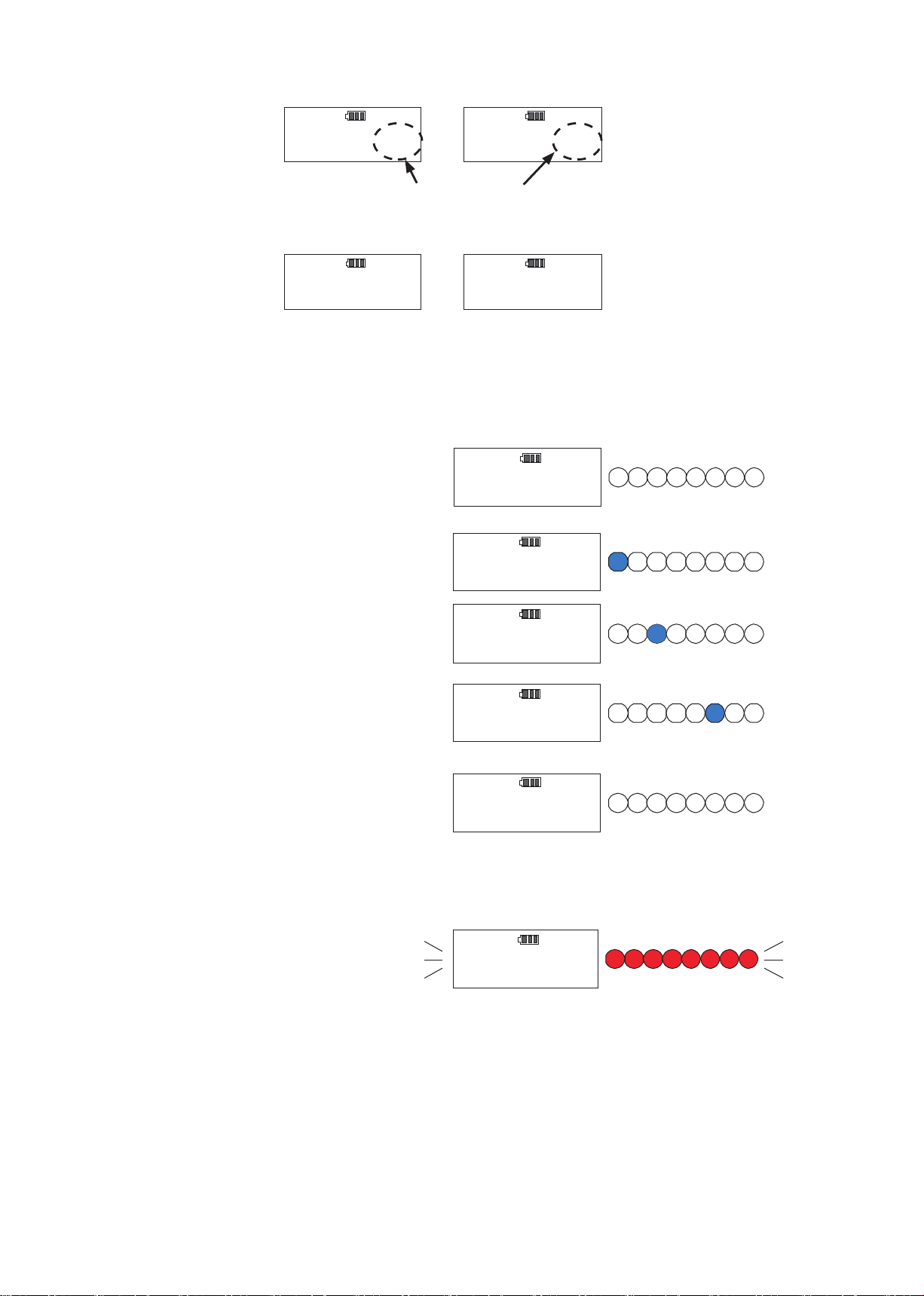
Example) Inspection by re-tightening method.
Retighten the already tightened bolt. (LED will not turn
on at no loading condition.)
When it reaches 7.5% of the maximum torque capacity,
the blue LED turns on.
As torque increases, the blue LED moves toward right.
Stop tightening as the bolt starts to rotate again, and it
reads out the torque value at that moment.
Press MEM key to save the data.
(If the set torque is Zero values, Auto memory/Reset is
not effective.)
Press C key to clear the data.
Cautions)
In case you accidentally apply over 105% of the max
capacity torque.
The applied torque value and "----" appears on LCD
alternately while the red LED blinks and the buzzer
goes off.
In this situation, data saving is not possible by pushing
MEM key.
01
0.0
N・m
A
01
20.0
N・m
A
Blue
01
40.0
N・m
A
Blue
01
82.0
N・m
A
Blue
02
0.0
N・m
A
01
---.-
N・m
A
Red
Blinking
13
Use ▲▼ key to select the lowest end of the data range to delete, and press MD key.
It shows the number of data to delete (Press C key to cancel).
Keep MD key pressed, and press C key, then the selected range of data will be deleted at one time.
The display returns to the measuring condition.
n
10
N・m n
10
N・m
Number of data to delete
01
0.0
N・m
A
J 01
0.0
N・m
A
⑦ Inspection use by Re-tightening torque method/Loosening torque method (Peak Mode)
In Preset tightening mode or Judgement tightening mode, set the target and lower/upper limit torque to 0.
(Please refer to P19 for setting procedures.)
CPT has various kinds of modes and settings according to customer's usage.
Please refer to the table below for available modes and detailed functions of CPT.
① Settings
Common Settings
Settings on Preset Tightening Mode
Setting on Judgement Tightening Mode
Other Parameter Settings
Subject Display Delivery Condition Select
1 Selecting Subject to Set -- MODE-S PARA_S
2 Measurment Mode SEL PRESET JUDGE
3Target Range
[%] rAng 0% 0~10 %
4 Target Torque 10kinds St 0 Below Max. Torque
5 Lower Limit 10kinds Lo 0 Below Upper Limit
6 Upper Limit 10kinds HI 0 Below Max. Torque
7 Tightening Direction 10kinds tUrn CW CCW
8 Measurement Unit USEL N・m kgf・cm / kgf・m / lbf・in / lbf・ft
9 Auto Memory Reset Timer Ar 00.0、0.1~5.0 sec
10 Buzzer Output bU ON OFF
11 Baud Rate bPS 2400 4800/9600/19200
12 Data Length dL 7BIT 8BIT
13 Parity Prt NONE ODD/EVEN
14 Setting Default dFLt DFLT-N DFLT-Y
14
8. Various Settings
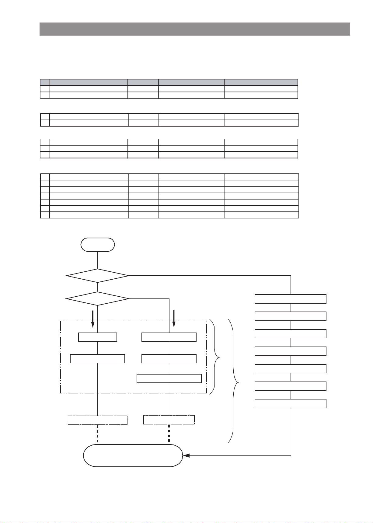
② Flow chart on settings
Tightening Mode
Select Subject
MODE_S
PARA_S
PRESET JUDGE
Complete
To Run Measuring Mode
Settings
Target Range
Set Torque Memory A
Set Torque Memory B ~J
10 kinds of registration
1 kind of registration
Target Torque Setting
Lower Limit Setting
Upper Limit Setting
Tightening Direction Setting
Reset Setting
Auto Memory /
Lower Limit Setting
Target Torque Setting
Buzzer Output Setting
Return to Default Setting
Measurement Unit
Baud Rate
Data Length
Parity
③ Setting on Preset tightening mode
Use ▲▼ key to set the counter to 00 (RUN mode).
Keep MD key pressed for 2 seconds or more seconds,
then it proceeds to the setting subject selection.
●Selecting setting subject
Select MODE_S (setting on tightening mode and
torque setting), or PARA_S (other parameter
settings).
Use ▲▼ key to select MODE_S and press MEM key
to proceed to the next.
Press MD key to proceed without saving. (Press C key
to return to RUN measuring mode.)
●Tightening mode setting (Default: PRESET)
Use ▲▼ key to select "PRESET" and press MEM
key to conrm. It proceeds to Data Clearance display
shown below (If you press MD key, it proceeds to the
next without saving. If you press C key it returns to
RUN measuring mode).
●Data Clearance Conrmation
Press MEM key to save the tightening mode and
proceeds to the next.
(Press C key to return to tightening mode setting).
If you do not want to change the tightening mode, you
can skip the Data Clearance Conrmation.
※When you change the tightening mode, tightening data
will be cleared. Record the data in advance in necessary.
00
0.0
N・m
S E L
CLR_OK
S E L
CLEAR
Data clearance
--
MODE_S
--
PARA_S
S E L
JUDGE
S E L
PRESET
15
Select
Select
Select
Use ▲▼ key to select number and press MEM key to
save and proceed to the next.
Press MD key to proceed without saving. (Press C key
to return to RUN measuring mode).
●Target torque setting (Default setting: 0)
Set the rst target torque. 10 different torque values
can be registered and each will be expressed in
alphabet A-J on display.
Press ▲ key to select digit and ▼ key to select
number. Press MEM key to save and proceed to the
next. (Press MD key to proceed without saving. Press
C key to return to RUN measuring mode.).
In the same way as the rst target torque setting,
set the second "B", and all the way to the 10th "J".
After completing 10th "J" setting, it returns to RUN
measuring mode.
If you want quit on the way, press C key to return to
RUN measuring mode.
④ Setting on Judgement tightening mode
Use ▲▼ key to set the counter to 00 (RUN measuring
mode).
Keep MD key pressed for 2 seconds or more seconds
to proceed to the setting selection.
●Selecting subject to set
Select MODE_S (setting on tightening mode and
torque setting), or PARA_S (other parameter settings)
.
Use ▲▼ key to select MODE_S and press MEM key
to proceed to the next.
Press MD key to proceed without saving. (Press C key
to return to RUN measuring mode.)
●Tightening mode setting
(Default setting: PRESET)
Using ▲▼ key to select "JUDGE", and press MEM key
to conrm. (If you press MD key, it proceeds to the next
without saving. If you press C key, it returns to RUN
measuring mode)
rA ng
00
%
05
%rA ng
S t
000.0A
N・m
S t
020.0A
N・m
S t
000.0B
N・m
S t
030.0B
N・m
16
Before Setting After Setting
●Target range setting (Default setting: 0%)
Set the target torque range to be indicated by blue LED. Select target range by percentage (%) based on the target
torque (select in 0-10% range).
Example: When target torque is 100N ・m and Target range 5%, the actual range will be 100N ・m-105N ・m
(The target range will be lit by blue LED).
00
0.0
N・m
--
MODE_S
--
PARA_S
S E L
PRESET
S E L
JUDGE
Select
Before Setting After Setting
Before Setting After Setting

●Data Clearance Conrmation
Press MEM key to save the tightening mode and
proceeds to the next.
(Press C key to return to Tightening mode setting.)
Data clearance conrmation (below) will be skipped if
the tightening mode is not changed.
Go to next Step.(Lower limit setting)
※ If you change the tightening mode, tightening data will be
cleared. Record the data in advance, if necessary.
●Lower limit value setting (Default setting: 0)
Set the lower limit torque of the rst setting torque.
10 different torque set can be registered and each will be
expressed on display as A through J.
Use ▲ key to select digit and ▼ key to select number.
Press MEM key to save and proceed to the next (Press
MD key to proceed without saving. Press C key to
return to RUN measuring mode.)
●Upper limit value setting (Default setting: 0)
Set the upper limit of the rst target torque.
Use ▲ key to select digit and ▼ key to select number.
Press MEM key to save and proceed to the next. (Press C
key to return to RUN measuring mode.)
●Setting tightening direction (Default setting: 0)
Set tightening direction of the rst setting torque.
Use ▲▼ key to select CW (clockwise) or CCW
(counter-clockwise) and press MEM key to save and
proceed to the next. (Press C key to return to RUN
measuring mode.)
In the same way as the rst torque setting, set
the second "B", and all the way to the 10th "J".
After completing 10th "J" setting, it returns to RUN
measuring mode.
If you do not need to set the next torque, press C key
to return to RUN measuring mode.
S E L
CLR_OK
S E L
CLEAR
Data clearance
17
Lo
000.0A
N・m
Lo
020.0A
N・m
H I
030.0A
N・m
H I
000.0
A
N・m
tUrn
CWA
CCWA
tUrn
Lo
000.0B
N・m
Lo
030.0B
N・m
Select
Before Setting After Setting
Before Setting After Setting
Before Setting After Setting

00
0.0
N・m
--
MODE_S
--
PARA_S
Ar
0.0
Ar
0.5
18
Select
Before Setting After Setting
⑤ Other settings
Use ▲▼ key to set the memory counter to 00 (RUN
measuring mode).
Keep MD key pressed for more than 2 seconds till it
the display changes.
●Selecting setting subject
Select MODE_S (setting on tightening mode and
torque setting), or PARA_S (other parameter settings).
Use ▲▼ key to select PARA_S and press MEM key to
save and proceed to the next.
(Press MD key to proceed without saving. Press C key
to return to RUN measuring mode).
●Setting measurement unit (Default: N
・
m)
Select the torque unit
(N
・
m/kgf
・
cm /kgf
・
m/lbf
・
in /lbf
・
ft)
The measured torque and the set torque will be
converted into the selected torque unit.
Use ▲▼key to select the torque unit and press MEM
key to save and proceed to the next.
(If you press MD key, it proceeds without saving. If you
press C key, it returns to RUN measurement mode).
●Setting Auto memory/Reset timer (Default: 0.0)
Set Auto memory/Reset timer. After tightening
completion, the auto memory function saves the data
automatically after the set timing, and proceed to the
next counter. (0.1 - 5 seconds)
If you set it to "00", then Auto memory/Reset function
will be ineffective.
Use ▲▼ key to select the timing (second) and press
MEM key to save and proceed to the next.
(Press MD key to proceed without saving. Press C key
to return to RUN measuring mode.)
UNIT
USEL
N・m
Select the torque unit
(N
・
m/kgf
・
cm /kgf
・
m/lbf
・
in /lbf
・
ft)
Unit conversion table
Conversion factores
N・m→kgf・cm 10.1972
N・m→kgf・m 0.101972
N・m→lbf・in 8.8508
N・m→lbf・ft 0.73756
Rounding of the converted gures
100.0[N
・
m] × 0.73756 = 73.756 ≒ 73.8[lbf
・
ft]
73.8[lbf
・
ft] ÷ 0.73756 = 100.05 ≒ 100.1[N
・
m]
※Converted gures are rounded as above.
Accordingly, the resulted gures may have a margin of errors.
※Unit conversion is made based on N.m values with the above conversion factors.
※ All the memory and torque setting values are converted when making a unit change.
19
●Sound option (Default setting: ON)
Choose whether or not to activate sound on any
tightening operations.
Use ▲▼ key and press MEM key to save and proceed
to the next. (Press MD key to proceed without saving.
Press C key to return to RUN measuring mode).
●Baud rate setting (Default: 2400bps)
Set the communication baud rate
(2400bps/4800bps/9600bps/19200bps)
Make sure to use the same baud rate between the
devices when outputting the data.
Use ▲ ▼ key to select the baud rate and press MEM
key to save and proceed to the next.
(Press MD key to proceed without saving. Press C
key to return to RUN measuring mode.)
● Data length setting (Default: 7 bit)
Set the communication data length (7 bit / 8 bit)
Use ▲▼ key to select the data length and press MEM
key to save and proceed to the next.
(Press MD key to proceed without saving. Press C
key to return to RUN measuring mode.)
●External output parity setting (Default: NONE)
Set the communication parity. (NONE、EVEN、ODD)
Use ▲ ▼ key to select the parity and press MEM key
to save and proceed to the next.
(Press MD key to proceed without saving. Press C
key to return to RUN measuring mode.)
●Return to default setting
Return all settings to the default setting conditions.
Use ▲▼ key to select DFT-Y and press MEM key. All
the settings will return to the default setting conditions.
(If you press MEM key, MD key or C key at "DFT-N"
condition, it returns to RUN measuring mode without
saving.)
bU
ON
Select
bU
OFF
dFLt
DFT-N
DFT-Y
dFLt
Select
2400
bPs
19200
bPs
Select the baud rate
(2400bps/4800bps/9600bps/19200bps)
Select
7BIT
dL
8BIT
dL
NONE
Prt
EVEN
Prt
Select
Select
Select the parity
(NONE、EVEN、ODD)
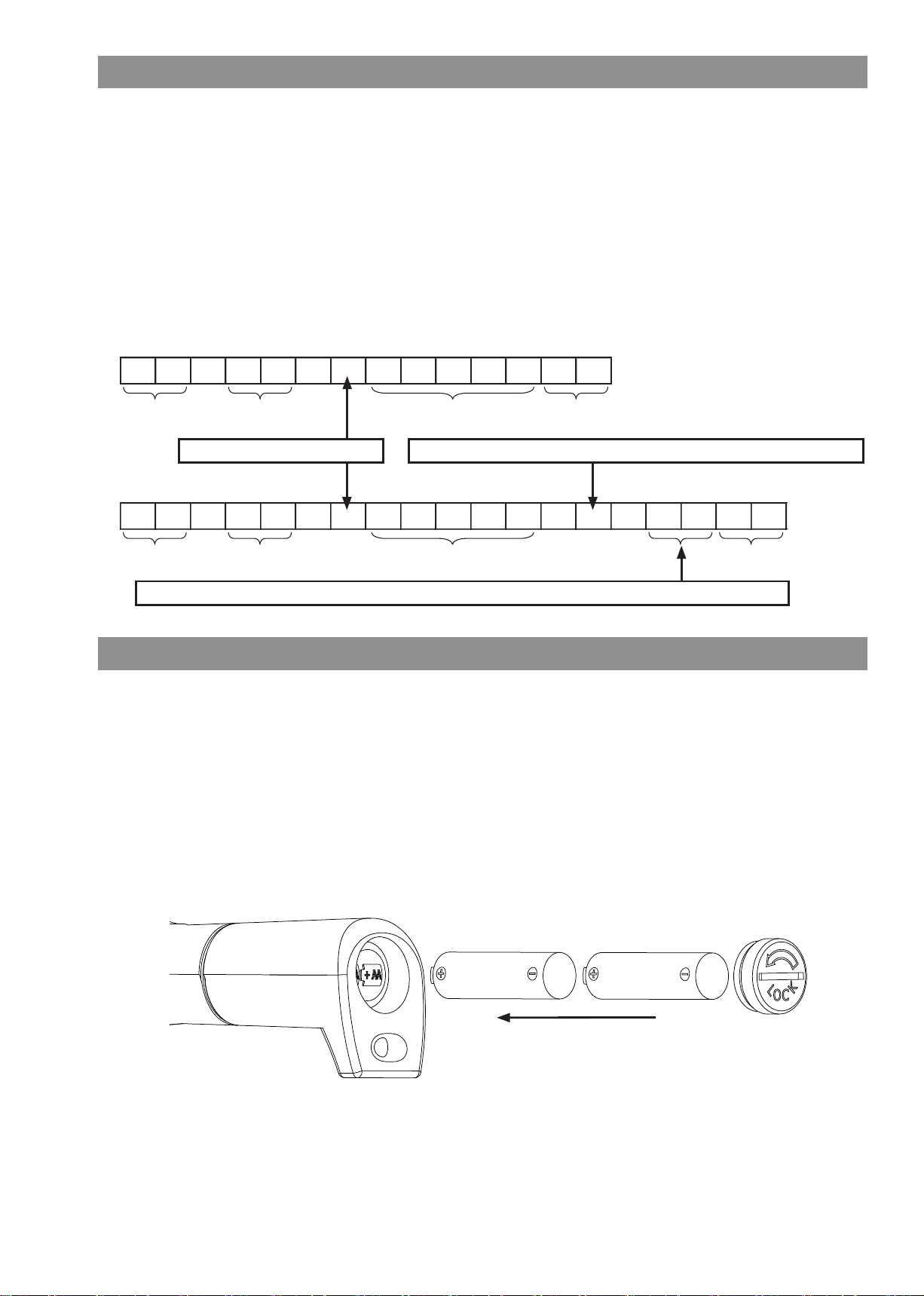
Insert AA batteries (2pc) inside the handle of the main body.
Please be careful not to place them at wrong polarity (see below illustration).
Both nickel-hydrogen battery and alkaline battery can be used.
However, nickel-hydrogen battery is more recommendable (See below ※).
Please refrain from using a new and old battery together, or different type of batteries at the same time in order to
maintain stable performance.
※Nickel-hydrogen battery and alkaline battery have different nal voltage.
CPT indicates battery shortage by showing "LOBATT" based on rechargeable nickel-hydrogen battery voltage.
Therefore, when using alkaline batteries, it may show the "LOBATT" display before using up the batteries.
10. Battery
9. External Output
①Communication settings for external output
Synchro system :
asynchronous communication method
Baud rate : 2400/4800/9600/19200bps
Data length : 7bit/8bit
Stop bit : 1 bit
Parity : NONE / EVEN / ODD
②PC output
Connect CPT to PC with the dedicated communication cable (No.585). Set the PC’s baud rate in line with CPT setting.
※Communication cable(No.585) is sold separately.
External output format
○Preset tightening mode
○Judgement tightening mode
R E , 5 0 , 1 0 0 . 0 , A , O K C R LF
Alphabetical symbol for the set torque. If the torque is zero, it shows "-".
Header Counter(2g.) Torque(Decimal point) Delimiter
CW : Blank、CCW : Minus (-)
Judgement result : "LO","OK","HI".When the set torque is zero, or tightening torque is zero, it shows "--".
R E , 5 0 , 1 0 0 . 0 C R LF
Header Counter(2g.) Torque(Decimal point) Delimiter
20
This manual suits for next models
2
Table of contents
Other Tohnichi Tools manuals


Popular Tools manuals by other brands


General
General F-36 T-28 Setup & Assembly Manual

Alemlube
Alemlube 200A owner's manual

Spirax Sarco
Spirax Sarco 8200L Installation and maintenance instructions

Bihui
Bihui TEXTURE SCVU8 Usage instructions

Flexco
Flexco FSK2MP Safety and operating manual

Ingersoll-Rand
Ingersoll-Rand 324 Series Product information