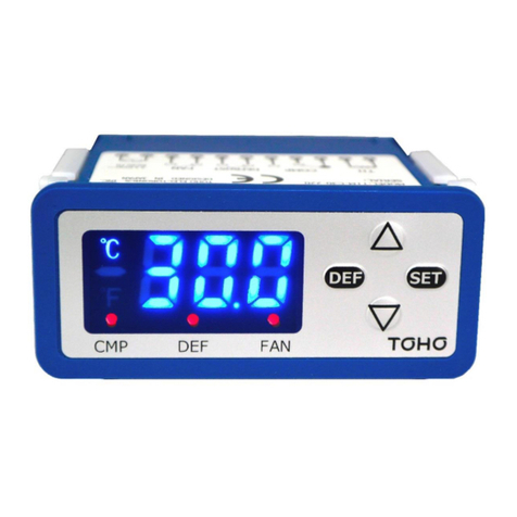
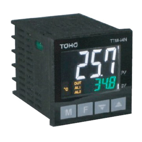
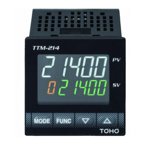
TOHO TTM-200 Series User manual

TOHO ELECTRONICS INC.
TTM-200
DIGITAL CONTROLLER
TTM-204
(Black)
TTM-204
(Gray)
TTM-205TTM-207 TTM-209
TTM-204
JISQ 9001:2000
JISQ14001:2004
JSAQ097、JSAE1356
本製品は審査登録(ISO9001)された工場で製造されたものです。本製品は審査登録(ISO9001)された工場で製造されたものです。
QMS,EMS
Accreditations
R001、
RE005
QMS,EMS
Accreditations
R001、
RE005

●Improvement of the controllability with new PID
algorithm
①Time until it is stabilized from a control start is shortened
②Loading the jump less control which controls the overshoot after
the disturbance
③You can chose from three kind of PID control that can be chosen
●Full multiple inputs
Established the input specication to be one type of the thermocouple
(13 types), the platinum resistance temperature sensor (2 types),
voltage (5 types) and the electric current (1 type). (Modification of
setting with parameter)
●Sampling period
Realized acceleration in 200mS
●Utilizes a liquid crystal display
①The indication range has been extended to present 5 columns
②Actualized the various indication with 11 segments
③Adopted LED to back light
●PV color auto-change
Display color of Process value (PV) can be optionally set from Red,
Orange and Green as compare with Setting value (SV).
●Compact size
Depth is compact size, TTM-204 is only 55mm, and TTM-205, 207 and
209 are also only 65mm.
●Loader communication function
The best for the setup work of a parameter
Cable: Option (sold separately)
Software: Free option ---- It can download from our web site
●Abundant output type
Relay contact, SSR-driving, Open collector, Voltage (5 types) and
Electric current
●Substantial option function
①CT input (Max. of 2 points) ②Event input (Max. of 4 points) ③Event
output (Max. of 7 points. However, when 7 points are used, you can
not use the control output.)
●External standards
We have acquired "CE", "UL" and cUL.
●Protection structure (Available only for TTM-204)
Corresponding to "IP66"
●Valve position proportionality control
The function carries out valve position proportionality control without
feedback resistance.
●Two choices of case colors (Available only for TTM-204)
"Black" or "Gray" choice is possible to preference
●Blind function
The system can be configured so that only specific, selected
parameters are displayed from set of parameters.
●Simple timer function (independent three points)
The order of "After the dened time period passes, the control starts
or stops" can be controlled by one unit.
Also use by the timer independent is possible. (Event output ON/OFF)
●Priority screen
Without showing a parameter screen, a display and a setup can
be performed by indicating a necessary parameter screen on the
operation mode screen.
(Maximum of 16 screens)
●Digital PV lter
Corresponding to the sudden change of input value, it can apply the
lter with the software
●Manual control
A manual output function enables application of various
instrumentation systems
●Communication function
(RS485: An exclusive protocol / MODBUS)
The range extends up to the distance of 500m, and can connect up to
31 units concurrently.
With one host computer, it can remote consolidate watching "The
collection of the data" and "Change of each setting value" at the place
where it is far.
●Soft-start function
When the power supply is turned on, limitation can be put on
manipulated value during specic time in PID control.
●Delay timer (Available only ON/OFF control)
It is possible to make the action of control output (Main or auxiliary)
delay during specific time (setting). This can be used to protect the
freezer.
●Loop Error
This monitors the measured values and operation time in order to
detect errors in the control loop.
■Features
DIGITAL
CONTROLLER TTM-200
■Operation ow■Front Panel
OUT1 Output1 monitor (It appears when output)
OUT2 Output2 monitor (It appears when output)
OUT3 Output3 monitor (It appears when output)
OUT4 Output4 monitor (It appears when output)
OUT5 Output5 monitor (It appears when output)
OUT6 Output6 monitor (It appears when output)
OUT7 Output7 monitor (It appears when output)
RDY RDY lamp (It appears in the state of Ready)
COM
COM lamp (It blinks during communication)
DI1 DI1 monitor (It appears when DI1 operates)
DI2 DI2 monitor (It appears when DI2 operates)
DI3 DI3 monitor (It appears when DI3 operates)
DI4 DI4 monitor (It appears when DI4 operates)
TMR TIMER lamp
(It appears when timer operates)
TIME It appears when the setting is "Timer"
℃/°F
It appears when the setting is "Temperature"
PV Measured value indication, Character
indication, Timer set-up time indication
SV Set value indication, Operation quantity
indication, Timer remaining time indication
MODE Mode key
It is used when changing a screen.
FUNC Function key
It executes the function that is set
▲
Up key
It is used when making a setting value increase
It is used when changing input setting mode
▼
Down Key
It is used when making a setting value decrease
It is used when changing parameter screen
※OUT6 is not available for TTM-207.
TIME
℃
OUT1
OUT2
OUT3
OUT4
PV
SV
DI2
DI1
TMR
RDY COM
FUNC ▲▼
MODE
TIME
℃
OUT1
OUT2
OUT3
OUT4
OUT5
OUT6
OUT7
FUNC ▲▼
MODE
PV
SV
COM
RDY
DI1
DI2
DI3
DI4
TMR
Powersupplyturningon
Initialscreen
Operationmode
Setupitemchoicescreen
SET1toSET20
Eachsetting
ModeKey
twoseconds
Modekey
twoseconds
ModeKey
twoseconds
Modekey
twoseconds

■Standard specications
Input type Thermocouple K, J, T, E, R, S, B, N, U, L, WRe5-26, PR40-20, PLII (Input resistance 1MΩ)
RTD Pt100, JPt100
Electric current / voltage 4 to 20mADC (Input resistance 250Ω), 0 to 1VDC, 0 to 5VDC, 1 to 5VDC, 0 to 10VDC, 0 to 10mVDC (Input resistance 1MΩ or more)
Indication
(LCD Indication)
PV/Character indication LCD indication (with LED back light, luminous colors are Red, Orange and Green)
TTM-204/205 5 digits, height 10mm
TTM-207 5 digits, height 13mm
TTM-209 5 digits, height 20mm
SV/Setting indication LCD indication (with LED back light, luminous color is Red)
TTM-204/205 5 digits, height 8mm
TTM-207 5 digits, height 8mm
TTM-209 5 digits, height 10mm
Auxiliary indication part LCD indication (with LED back light, luminous color is Green)
TTM-204/205 1 digit, height 8mm
TTM-207 1 digit, height 8mm
TTM-209 1 digit, height 10mm
Each functional indication Red (OUT1, OUT2, OUT3, OUT4, OUT5, OUT6, OUT7, DRY, COM, DI1, DI2, DI3, DI4, TMR)
PV color auto-change Luminous color Red, Orange and Green
Luminous color
change range
Temperature input 0.0 to 999.9 or 0 to 999 (℃ )
Analogue input 0 to 9999 (digit)
Control PID
(With auto tuning)
(With self tuning)
Proportional band (P1) 0.1 to 200.0% of set limiter span
Proportional band side of Output 2 (P2) 0.10 to 10.00 times (Per main control proportional band)
Integration time (I) 0 to 3600seconds (with "0" integral action OFF)
Dierentiation time (D) 0 to 3600seconds (with "0" derivative control action OFF)
Proportion cycle (T1, T2) 0.1 to 120.0 seconds
Dead band (DB) Temperature input -999.9 to 999.9 or -999 to 999 (℃ )
Analog input -9999 to 9999 (digits) {The decimal point position is the specied position.}
ON/OFF Control sensitivity (C1, C2) Temperature input 0.0 to 999.9 or 0 to 999 (℃ )
Analog input 0 to 9999 (digits) {The decimal point position is the specied position.}
Output 1 and 2 O point Position selection setting SV unit setting High/Medium/Low
Positional setting Temperature input -999.9 to 999.9 or -999 to 999 (℃ )
Analog input -9999 to 9999 (digits) {The decimal point position is a specied position.}
Control output Relay contact 250VAC 3A (Resistance load) 1a contact point Minimum load 5VDC 100mA
SSR-driving voltage 0 to 12VDC (Load resistance 600Ω or more)
Open collector 24VDC 100mA
Current / voltage 4 to 20mADC (Load resistance 600Ω or less)
Voltage 0 to 1VDC (Load resistance 500KΩ or more), 0 to 5VDC (Load resistance 1KΩ or more), 1 to 5VDC (Load resistance 1KΩ or more)
0 to 10VDC (Load resistance 1KΩ or more), 0 to 10mVDC (Load resistance 500KΩ or more)
Sampling cycle 0.2 seconds
Setting and instruction
accuracy
(In ambient temperature 23℃
±10 degree)
Thermocouple K, J, T, E, R, S, B, N Larger one±(0.3%+1digit) of the instruction value or ±2℃ (23℃±10℃ )
However, -100 to 0℃ is ±3℃ , and -200 to -100℃ is ±4 ℃ . As for 400 ℃ or less of B thermocouple there
is no stipulation
U, L Larger one±(0.3%+1digit) of the instruction value or ±4℃ (23℃±10℃ ) Less than 0℃ is ± 6℃ .
WRe5-26 Larger one±(0.6%+1digit) of the instruction value or ±4℃ (23℃±10℃ )
PR40-20 ±9.4℃±1digit. There is no precision stipulation under 800℃
PLⅡ Larger one±(0.3%+1digit) of the instruction value or ±2℃
RTD Pt100, JPt100 Larger one±(0.3%+1digit) of the instruction value or ±0.9℃ (23℃±10℃ )
Current/voltage 0 to 1VDC, 0 to 5VDC ±0.3%±1digit of set limiter span (23℃±10℃ )
1 to 5VDC, 0 to 10VDC, 4 to 20mADC
0 to 10mVDC ±0.5%±1digit of set limiter span (23℃±10℃ )
Memory element EEPROM
Input power supply 100 to 240VAC (-15%, +10%), 50/60Hz, 24VAC/DC±10%, 50/ 60Hz
Weight TTM-204 : 120g TTM-205 : 210g TTM-207 : 260g TTM-209 : 300g
Power consumption TTM-204 less than 10VA (100 to 240VAC), less than 4W (24VAC/DC), TTM-205/207/209 less than 11VA (100 to 240VAC), less than 5W (24VACDC)
Accessories Simple instruction manual and Attachment (A handling description is sold separately.)
Standard Range of surrounding temperature humidity
(Compensating range such as precision)
23℃±10℃ , 45 to 75% RH
Range of use surroundings temperature humidity 0 to 50℃ , 20 to 90% RH (Avoid dewiness)
Range of preservation surroundings temperature humidity -20 to 70℃ (Avoid dewiness and freezing), 5 to 95% RH (Avoid dewiness)
Function Manipulated variable limiter
(MLH1, MLL1, MLH2, MLL2)
Upper limit (MLH1, MLH2) Digital output MLL1 to 100.0 (%), MLL2 to 100.0 (%)
Analogue output MLL1 to 110.0 (%), MLL2 to 110.0 (%)
Lower limit (MLL1, MLL2) Digital output 0.0 to MLH1 (%), 0.0 to MLH2 (%)
Analogue output -10.0 to MLH1 (%), -10.0 to MLH2 (%)
Upper limit lower limit setting of
manipulated variable change limiter
0.0 to 549.9 (%) (Function OFF by 0.0%)
Abnormal time manipulated variable
setting
Digital output 0.0 to 100.0 (%)
Analog output -10.0 to 110.0 (%)
Setting limiter (SLL, SLH) Upper limit (SLH) Temperature input
(SLL + 5.0) to SV setting range upper limit, (SLL + 5) to SV setting range upper limit (℃)
Analogue input (SLL + 5.0) to SV setting range upper limit (digit)
Lower limit (SLL) Temperature input
SV setting range lower limit to (SLH - 5.0), SV setting range lower limit to (SLH - 5) (℃)
Analogue input SV setting range lower limit to (SLH - 50) (digit)
Control mode (MD) Control stop, control beginning, manual control, timer1 operation, timer2 operation, and timer3 operation
Control types (CNT) PID type Type A (Normal PID control type)
Type B (Over-shoot protection type)
Type C (External disturbance protection type)
Type B mode Over-shoot protection Weak
Over-shoot protection Middle
Over-shoot protection Strong
Normal reverse action setting Reverse action
Normal action
Tuning type setting Main auto-tuning (Main PID/position proportionality control)
Main self-tuning (Main PID/position proportionality control)
Auxiliary auto-tuning (Main PID/auxiliary PID)
Auxiliary self-tuning (Main PID/auxiliary PID)
Main/auxiliary auto-tuning (Main PID/auxiliary PID)
Output gain setting(MV1G, MV2G) 0.0 to 1000.0 (%)
PV correction, 0 point setting (PVS) Temperature input -999.9 to 999.9 (℃ )
Analog input -9999 to 9999 (digit)
PV correction, gain setting (PVG) 0.500 to 2.000 (times)
PV input lter (PD) 0.0 to 99.9 (seconds)
Anti reset windup 0.0 to 110.0 (%) (Function OFF by 110.0% setting)
Manual reset (PBB) 0.0 to 100.0 (%) (-100.0 to 100.0 (%) if there is auxiliary control)
Loop abnormal time setting Main control loop abnormal time setting 0 to 9999 (seconds)
Auxiliary control loop abnormal time setting 0 to 9999 (seconds)

■Standard specications
Function Timer driving mode (TMF) Three points. 0 minute and 00 second to 99 minutes and 59 seconds. 0 hour and 00 minute to 99 hours and 59 minutes.
Timer repetition frequency: 0 to 99 times (With 0 unlimited frequency)
Accuracy: ±(1.5% + 0.5 seconds) of setting time
Function: Auto start, Manual start, Event start, SV start, DI start
Delay timer (FDT) 0 to 99 (minutes) Main/auxiliary common
Decimal point movement (DP) Indication below decimal point. Yes/No
Manual control Manual control is possible. (Balance-less / Bump-less)
RUN/READY Switching of RUN/READY is possible.
Blind function An optional parameter screen can be set up in the non-indication.
Auto tuning coecient (ATG) 0.1 to 10.0 times
Auto tuning sensitivity (ATC) Temperature input 0.0 to 999.9 or 0 to 999 (℃ )
Analog input 0 to 9999 (digits)
Function key A function key can be chosen from "Figure movement", "MD/ready", "AT start/stop", "Timer start/reset", "Reverse screen turning", "ENT", "Bank change"
and "Auto/manual change". Settlement of push time (0 to 5 seconds)
Priority screen An optional parameter screen can be indicated in the operation mode. (Maximum of 16 points)
Lock function (LOC) Four modes (OFF, ALL Lock, Operation mode lock, and lock except operation mode)
Self-diagnostic function EEPROM data check (Err0), A/D converter action check (Err1), auto-tuning check (Err2), watch-dog timer equipped
Ramp function Action When modify SV, set up the SV variation per minute
Setting range Temperature input 0.0 to 999.9℃/minute (Ramp function turns OFF by 0.0)
Analog input 0 to 9999 digit/minute (Ramp function turns OFF by 0)
Setting unit Temperature input 0.1℃/minute
Analog input 0.1 digit/minute
Valve function Motor stroke time 0.1 to 999.9 (seconds)
Motor drive dead band 0.0 to 100.0 (seconds)
Initialization mode Password setup, blind screen one time call setup, setting value backup and set value initialization
Since a password is required for this mode when making a setting change, please be sure to keep the password.
Bank setting Setting the parameter of set 1 to 17 (A maximum of 16 points)
Soft-start (Main control) Output setting MLL1 to MLH1 (%)
Time setting 00:00 to 99:59 (minutes), Function OFF by 00:00 (minutes)
■Option specications
Auxiliary output
(2 points)
(Common
Terminal)
Relay contact 250VAC 1A (resistance load) 1a contact point
Open collector 24VDC 100mA
Setting range (Upper and Lower
limit)
Temperature input -1999.9 to 2999.9、-19999 to 29999(℃)
Analog input -19999 to 29999(digit)
Sensitivity Temperature input 0.0 to 999.9、0 to 9999(℃)
Analog input 0 to 9999(digit)
Delay timer 0 to 9999 (seconds)
DI input
(Max. 4 points)
Function Bank switch, RUN/READY switch (At the time of contact point closing is Ready), Auto/Manual switch (At the time of contact point closing is Manual), Reverse action/
Forward action switch (At the time of contact point closing is Forward action)
Auto tuning STOP/START (At the time of contact point closing is Auto tuning Start), Timer STOP/START (At the time of contact point closing START)
Input specication No voltage contact point. Active switching is possible at the time of the input.
Minimum input time 200mS
When ON electric current Maximum 10mADC
When OFF electric current Maximum 6VDC
Terminal permission resistance When ON: Maximum 333Ω, When OFF: Minimum 500KΩ
CT input
(2 points)
Measurement electric current range 0.0 to 50.0A
Setting electric current range 0.0 to 30.0A (Setting resolution 0.1A). However, the function is turning o at 0.0.
Setting accuracy ±5% (0.1A or less is outside accuracy)
Wire break detection ON time of control output above 300mS
Welding detection OFF time of control output above 300mS
Communication Communication Loader communication
Communication standard RS-485 (1:31) TTL (1:1)
Communication terminal Terminal stand Loader communication private terminal
Protocol TOHO exclusive protocol/MODBUS (RTU)/MODBUS (ASCII) TOHO exclusive protocol/MODBUS (RTU)/MODBUS (ASCII)
Direction of information Half duplex Half duplex
Synchronous system Asynchronous Asynchronous
Transmission code ASCII ASCII
Interface RS-485 (two lines) TTIL level
Transmission speed 2400, 4800, 9600, 19200, 38400bps 2400, 4800, 9600, 19200, 38400bps
Communication distance 500m
Response delay time 0 to 250mS 0 to 250mS
Communication switch Writing is impossible/Writing is possible/Simultaneous temperature rise master/Simultaneous temperature rise slave.
Character Start bit: 1 bit xation Start bit: 1 bit xation
Stop bit: 1/2 bit Stop bit: 1/2 bit
Data length: 7/8 bit
* MODBUS: In case of ASCII --- 7 bits xation
In case of RTU --- 8 bits xation
Data length: 7/8 bit
* MODBUS: In case of ASCII --- 7 bits xation
In case of RTU --- 8 bits xation
Parity: No/Even number/Odd number Parity: No/Even number/Odd number
BCC check: No/Yes
* In case of MODBUS --- BCC Check is invalid
BCC check: No/Yes
* In case of MODBUS --- BCC Check is invalid
Address: 1 to 99 stations
* In case of MODBUS --- 1 to 247 stations
Address: 1 to 99 stations
* In case of MODBUS --- 1 to 247 stations
Transmission
output
Functional setting PV (Process value) output, SV (Setting value) output, MV1 (Main manipulated variable) output, MV2 (Secondary manipulated variable) output. Reciprocal change
possibility
Temperature input Scaling low limit to 2999.9 (℃ ), scaling low limit to 2999 (℃ )
Analogue input Scaling low limit to 29999 (digit)
Temperature input -1999.9 to scaling high limit (℃ ), -1999 to scaling high limit (℃ )
Analogue input -19999 to scaling high limit (digit)

■Input and scale range
Thermocouple
Measurement/measurement range
Indication resolution
K ℃ -200.0 to 1372.0 1℃/0.1℃
J ℃ -200.0 to 1200.0 1℃/0.1℃
T ℃ -200.0 to
400.0 1℃/0.1℃
E ℃ -200.0 to 1000.0 1℃/0.1℃
R ℃ -50.0 to 1768.0 1℃
S ℃ -50.0 to 1768.0 1℃
B ℃ -0.0 to 1800.0 1℃
N ℃ -200.0 to 1300.0 1℃/0.1℃
U ℃ -200.0 to
400.0 1℃/0.1℃
L ℃ -200.0 to
900.0 1℃/0.1℃
WRe5-26 ℃ 0.0 to 2300.0 1℃
PR40-20 ℃ 0.0 to 1880.0 1℃
PLⅡ ℃ 0.0 to 1390.0 1℃/0.1℃
RTD
Measurement/measurement range
Indication resolution
Pt100(JIS/IEC) ℃ -200.0 to 850.0 1℃/0.1℃
JPt100(JIS) ℃ -200.0 to 510.0 1℃/0.1℃
Current and voltage
Measurement/measurement range
Indication resolution
0 to 1VDC
-19999 to 29999
Indication width is less than
20000.
A decimal point position can
be changed arbitrarily.
0 to 5VDC
1 to 5VDC
0 to 10VDC
0 to 10mVDC
4 to 20mADC
■Output connection setting
Main output
Auxiliary output
Event output
RUN output
RDY output
Timer1 output
Timer1 output at on delay
Timer1 output at o delay
Timer1 output at on + o delay
Timer2 output
Timer2 output at on delay
Timer2 output at o delay
Timer2 output at on + o delay
Timer3 output
Timer3 output at on delay
Timer3 output at o delay
Timer3 output at on + o delay
Transmission output (When OUT1 and OUT2 are analogue output)
■Option Specications (Continued)
Remote SV Input
Input Type (Current/Voltage Multi-Input)
0 to 1VDC, 0 to 5VDC, 1〜5VDC, 0 to 10VDC, 4 to 20mADC
Measurement/Range of Setting -19999 to+29999 (decimal point can be set at any location)
Range of Display (Full Scale: Range
of FSL2 to FSH2)
0 to 1VDC, 0 to 5VDC,
0 to 10VDC
High Limit: +12% of full scale
Low Limit: Maximum of -2% of full scale
1 to 5VDC, 4 to 20mADC High Limit: +12% of full scale
Low Limit: -12% of full scale
Resolution ±0.3% of full scale+1 digit
Display scaling High Limit (FSH2): FSL2 to 29999 (digit)
High limit (FSH2)/Low limit (FSL2) Low Limit (FSL2): -19999 to FSH2 (digit)
Display Resolution Performance 20000 or less
PV Correction Zero-Point Setting (PVS2)
-9999 to 9999 (digit)
PV Correction Gain Setting (PVG2) 0.500 to 2.000 (Multiple)
PV Input Filter (PDF2) 0.0 to 99.9 (seconds)
Local/Remote Switch Local, remote 1 (scaling with SLL1 and SLH1)
Remote 2 (scaling with FSL2 and FSH2)

Output functional allotment (○:Allotment is possible、×:Allotment impossibility)
Output types Control output Auxiliary output
Output1 Output2 Output3 Output4 Output5 Output6 Output7
Main output (Heating) ○ ○ ○ ○ ○ ○ ○
Auxiliary output (Cooling) ○ ○ ○ ○ ○ ○ ○
Transmission ○ ○ × × × × ×
Event output ○ ○ ○ ○ ○ ○ ○
Timer output ○ ○ ○ ○ ○ ○ ○
Event function 1
Function
No
Deection upper and
lower limit
Deection upper limit
Deection lower limit
Deection range
Absolute value upper
and lower limit
Absolute value upper limit
Absolute value lower limit
Absolute value range
Addition function
No
Maintenance
Standby sequence
Delay timer
Maintenance + Standby
sequence
Maintenance + Delay
timer
Standby sequence +
Delay timer
Maintenance + Standby
sequence + Delay timer
Control linkage function
All mode
RUN/MAN mode only
RUN mode only
Event function 2
(PV abnormal)
Function
No
Exsist
Addition function
No
Maintenance
Delay timer
Maintenance + Delay
timer
Control linkage function
All mode
RUN/MAN mode only
RUN mode only
Event function 3
(CT abnormal)
Function
No
CT1 abnormal
CT2 abnormal
CT1 abnormal + CT2
abnormal
Addition function
No
Maintenance
Delay timer
Maintenance + Delay
timer
Control linkage function
All mode
RUN/MAN mode only
RUN mode only
Event function 4
(Loop wire break)
Function
No
Exsist
Addition function
No
Exsist
* Event polarity function
available
■Point of contact output mode■Timer drive mode
Start mode
1 Auto start
2 Manual start
3 SV start
4 DI1 start (Possible to set when option is equipped)
5 DI2 start (Possible to set when option is equipped)
6 DI3 start (Possible to set when option is equipped)
7 DI4 start (Possible to set when option is equipped)
8 Event 1 start
9 Event 2 start
10 Event 3 start (Possible to set when option is equipped)
11 Event 4 start (Possible to set when option is equipped)
12 Event 5 start (Possible to set when option is equipped)
13 Event 6 start (Possible to set when option is equipped)
14 Event 7 start (Possible to set when option is equipped)
*Each Start has ON delay/OFF Delay
ON delay: After time-up control stop or event output OFF
OFF delay: After time-up control stop or event output ON

■Wiring
■Terminal explanation
Communication Please connect the terminal of A and B rightly.
(Please use a converter when it is not RE-485)
Output
(Right reverse
change is possible)
Relay point of
contact
C: Common, No: Normal open
SSR driving Please connect directly with INPUT+ and - by the
side of SSR.
Transmission,
Open collector
Please be connected to polarity of + and - with
care
CT Please connect a specied current transformer directly. (CTL-6-P-H)
PV input/
AI input
Thermocouple Please be connected to polarity of + and - with
care
Current/
voltage
Please be connected to terminals A, B and b with
care
DI COM: Common (The polarity can be switched)
AI input Please be connected to polarity of + and - with care
1
2
3
4
5
6
7 Output3※
Output4※
Output3・4※
8
11
12
9
10
−
+
+
−
Output2
Power
Input
7
8
9
+
+
−
7
8
9
NO
NO
C
Output1
A
B
13
14
15
16
17
18
Communication(RS-485)
CT1
CT1 CTInput
CT2
CT2
b
B
A
DIInput
15
16
17
18
DI1
DI1(COM)
DI2
DI2(COM)
11
12
10
11
12
10
11
12
10
3
4
5
6
C
NO
C
NO
3
4
5
6
−
+
−
+
Other
Output
Relay
Output
Other
Output
Relay
Output
Other
Output
Relay
Output
OpenCollector
Output
Relay
Output
RTD TC/10mV
PV
I/V
Power
3
4
5
6
7
8
9
10
11
12
−
+
−
+
−
+
−
+
−
+
RTD I/VTC/10mV
3
4
5
6
7
8
9
10
11
12
C
NO
C
NO
C
NO
C
NO
C
NO
22
23
24
22
23
24
22
23
24
b
B
A
+
−−
+
19
20
21
NO
NO
C
19
20
21
+
+
−
1
2
3
4
5
6
7
8
9
10
11
12
Output2
Output5
Output6
Output7
※
※
※
Output1
13
14
15
16
17
18
19
20
21
22
23
24
CT1
CT1
CT2
CT2
+
−
Output3※
Output4※
Output3・4※
AIinput(Voltage/current)
Input
25
26
27
28
29
30
31
32
33
34
DI1
DI1(COM)
DI2
DI2(COM)
DI3
DI4
DI3,4(COM)
DIInput
CT
A
B
Communication(RS-485)
OpenCollector
Output
Relay
Output
PV
Power
3
4
5
6
7
8
−
+
−
+
−
+
11
12
13
+
+
−
3
4
5
6
7
8
C
NO
C
NO
C
NO
11
12
13
NO
NO
C
23
24
NO
C
23
24
+
−
1
2
3
4
5
6
7
8
Output2
Output5
※
Output1
17
18
19
20
21
22
23
24
A
B
CT1
CT1
CT2
CT2
CTInput
Output7
※
Communication(RS-485)
19
20
21
22
23
24
DI1
DI1(COM)
DI2
DI2(COM)
DI3
DI3(COM)
DIInput
9
10
11
12
13
14
15
16
+
−
Output3※
Output4※
Output3・4※
AIinput(Voltage/current)
Input
14
15
16
RTD
b
B
A
14
15
16
TC/10mV
PV
−
+
14
15
16
I/V
+
−
OpenCollector
Output
Relay
Output
OpenCollector
Output
Relay
Output
TTM-204
TTM-205、209
TTM-207
※Please use less than 6mm width terminal
※ Output 3 to 7 (Terminals 19 to 21and 7 to 12) are possible to select from either relay output or open collector.
※ Output 3 to 5 and 7 (Terminals 11 to 13, 7 to 8, 23 to 24) are possible to select from either relay output or open collector.
※ Output 3 and 4 (Terminals 7 to 9) are possible to select from either relay output or open collector.

■Dimensions
■Panel Installation
b
L
Formountingasingle
Packing
Formountingnpieces
MODE FUNC
TTM-204
SV
PV
OUT1 OUT2 OUT3 OUT4 RDY COM DI1 DI2 TMR
TIME
C
F
B D
2
C
6
TOHO
A
a
cd
*For this panel installation, please be careful suciently to avoid any of damage.
Model a b c d A B C D L
TTM-204 45 +0.6
-0 45 +0.6
-0 60 48 48 48 2 55 (Bxn-3) +0.6
-0
TTM-205 92 +0.6
-0 45 +0.6
-0 120 48 96 48 2 65 (Bxn-3) +1
-0
TTM-207 68 +0.6
-0 68 +0.6
-0 90 72 72 72 2 65 (Bxn-3) +1
-0
TTM-209 92 +0.6
-0 92 +0.6
-0 120 96 96 96 2 65 (Bxn-3) +1
-0
TTM-204 TTM-205、207、209

■Advanced Features
●PID control by new algorithm
100℃ 200℃
0
1000
2000
3000
4000
Time(sec)
Temp.(0.1℃/dig)
0 100 200 300 400 500 600
NEWPIDTYPEB
NEWPIDTYPEC
NEWPIDNEWPID
Disturbance
●BLIND Function Setting
ShiftbyMODEkey
Shiftby△▽key
PressMODEkey
for10seconds
PowerON
InitialDisplay
4seconds OperationMode
MODEkey
☆1 ☆1 ☆1
Afterthe"Blink",pressFUNCkey,andpressMODEkey
PV/SVblindsettingdisplay
SettingbyFUNCkey.
Itisblinded,ifredcharactersofPV&SVinthebelowdisplayarenotshown.
BypressingModekeyeverytime,
thenfrom
willbeshownsequentially.
to
★★
★★
(Someitemsarenotdisplayedasparameters)
IntoeachSET
PressMODEkeyfor3secondswhen☆1display
Content of the above ★
1) In BLIND MODE, either 「ON」 & 「OFF] is displayed on under each characters (SV display).
「ON」 is displayed. 「OFF」 is not displayed (BLIND).
2) To change characters in BLIND MODE by pressing 「FUNC」 key.
3) Power OFF for end of BLIND setting mode.
It is possible not to make the optional picture indicate by the key operation
In addition, please note that only measured value is displayed without displaying a
setting value in the case of the usual display when the SV setup screen is turned o.
●OFF point position movement of ON/OFF control
When the OFF point position movement is set to 0, the OFF point is the set value position.
=5
SV-20 SV-10 SV+10
Presetvalue(SV)
Controltemperature(=15)
Controltemperature(=15)
ON
OFF
SV-20 SV-10 SV+10
Presetvalue(SV)
ON
OFF
This is when o point position movement is set up with (+5).
Actually specication, there is no description change as above, but move above equal to
(+5) as a position of ON/OFF.
Case it made move on negative side, the OFF point moves to opposite side to description
above.
●Timer function
1. In the case of bread baking oven
●Put dough in the oven, and push the start key to the timer.
●The temperature is controlled by the heater and so on for the timer setup time.
●After timer count end control is stopped automatically
(It is used when making control STOP after the timer count ends.)
Startkey
Timeroperation
Controloutput
Setuptime Time-up
2. In case of packing machine and industrial machine, which control is started after the
completing the preparation of the peripheral device
●The count of the timer begins from point that turns on the power supply.
●The control output stops during timer setting time
●The control starts automatically after the timer count ends.
(It is used when making control starts after the timer count ends.)
Powersupply
Timeroperation
Controloutput
Setuptime Time-up
●Communication function
◦A connection example with the personal computer
Centralized supervision with the personal computer is possible with the connection like
the chart below.
TTM-200
RS-485
Converter
RS-232C
Hostcomputer
◦Loader communication
TTM-200
Hostcomputer
Anexclusivecable(Onerous)
※Loader cable specification
[Appearance and structure]
USBconnector Stereoplug
(Hostside) (TTM-200side)
1800mm
[Standard and performance]
USB I/F standard USB Specication 2.0 Conforming
DTE (Personal computer side) speed Up to 38400bps
Connector specication Personal computer side: USB
Temperature Controller side:
φ2.5mm Stereo plug
[Model]
TTM-LOADER

●Digital PV lter
It is the function to realize the CR lter eect on the software by performing primary delay
operation to the measured value (PV).
The eect of the lter can be set by the time constant.
(Time constant is the time that the PV value reaches up to about 63% when the input
changes on the step.)
Time
0%
100%
Inputsignal
Time
0%
100%
Time
Timeconstant(t)
0%
100%
63%
Readinginput
NoDigitalPVfilter
Timeconstant(t)=0
Readinginput
WithDigitalPVfilter
Timeconstant(t)>0
The use of Digital PV lter
1) Removal of high frequency noise --- The inuence of a noise when an electric noise
joining an input is mitigated.
2) A response can be delayed against the sudden change of the input.
●Self-tuning PID
Executionofself-tuning
(Self-tuningON)
①
①Atthetimeofsettingvaluechange
②Atthetimeofthetemperaturechangebydisturbance,
andatthetimeofhunchinggenerating
②
Temp.
Time
●Auto (RUN) / Manual function
The auto control and the manual control, they can be switched by the front key.
Manual operation is the function that is not concerned with the situation of a deviation,
but can set up and output the output for control arbitrarily (manipulation variable).
The system can be operated manually in the time of the system trial run and so on, when
to check of nal control element (a valve, heater, etc.) of operation is performed, when
the sensor breaks down by any chance, or when usual control can't be done.
There is the Balance-less Bump-less function, which holds down sudden change of control
output when switching the automatic control and manual control mutually. Furthermore,
it stops damage on the peripheral equipment by sudden change and the bad inuence to
a control system. So, you can operate in comfort.
Autocontrol Autocontrol
Previous
manipulatedvariable
Manipulated
variablemodification
Switch Switch
Manualcontrol Manualcontrol
Balance-lessBump-less Balance-lessBump-less
Balance-less Bump-less
●Ramp function
The ramp function is a matter of function made to have inclination against the change in
SV (Setting value).
As actual operation, the setting value of a dummy is made to change gradually toward
the setting value after changing. Then it controls to the setting value of the dummy.
The amount of change for around one minute of SV is set up.
When a rapid change of the control result is not allowed with the characteristic of the
control subject, and when the change course (inclination) of the control result becomes
important in a control subject, the eect of a ramp function is demonstrated, the eect of
the ramp function is demonstrated.
In addition, since only SV is changed, the result expected may not be obtained when it
expects great inuence to PV (measured value).
SV
SV
Set-uptime
Time
1min
*Asetupbythebankfunctionispossible.
ByvariationsetasRMP,asettingvalue
is changed from the temperature at
thetimeofstartingbeforeSV.
●Simultaneous temperature rise function
■Simultaneous temperature rise
・When simultaneous temperature rise control is exerted by multi-channels using the
RS-485 communication function, a master and slave are determined beforehand.
This permits reaching the respective goal values at the same time regardless of the
characteristic of each channel.
The channel, in which the time from the start of control to the reach to the goal value is
the longest, is specied as a master. The other channels are specied as slaves.
・The simultaneous temperature rise function is started at the start of run (including the
power ON time) or a change of setting value, and is ended when the master reaches
the goal value.
Controller1ch
Input Output
Sensor
Heater
Controller2ch
Input Output
Furnace
Sensor
Heater
Controller3ch
Input Output
Sensor
Heater
Controller4ch
Input Output
Sensor
Heater
◦How to use
1. Perform communication protocol settings to the TOHO protocol.
2. In the communication changeover setting, set the channel, in which the temperature
reaches the goal value latest, to the simultaneous temperature rise master, and then
set the other channels to the simultaneous temperature rise slaves.
3. Set the main control sensitivity.
During a simultaneous temperature rise, the slave side exerts ON/OFF control for the
current temperature of the master. Accordingly, set the sensitivity to a level that does
not cause chattering.
Note: Precautions on use
1. Perform auto tuning for each channel as required.
2. When using the simultaneous temperature rise function, do not perform communication
with the outside.

●Bank function
8 banks each with 16 setting that can be changed as optional parameter.
A desired state can be reached by adjusting the bank setting, but without modifying the
temperature setting or valve of the PID.
This can be done by setting up a parameter for an applicable bank that references the
temperature control for one unit.
Bank8
1
2
3
4
・
・
・
16
Optionalparameter
settingof16types
Bank3
1
2
3
4
・
・
・
16
Optionalparameter
settingof16types
Bank2
1
2
3
4
・
・
・
16
Optionalparameter
settingof16types
Bank1
1
2
3
4
・
・
・
16
Optionalparameter
settingof16types
●Remote SV
Signals from external sources become the controller parameters.
・Cascade control using remote SV
Cascade control is where the control signal for a single controller is applied to other
controllers, and the controller that receives control signals from an external source
convert those signals into parameters for control purposes.
As shown in the illustration above, cascade control can be achieved with the use of two
controllers.
TTM-204/205/207/209 TTM-205/207/209
Watertanktemperature Heatertemperature
Controloutput
Heatercontroltemperature
(remoteSV)
Heater
SSR
Controller Controller
●Position proportional control
■Position proportional control
・According to the operation amount required for PAD control, the valve opening is
changed by outputting an open signal or close signal to the valve on the basis of the
valve motor stroke time, so that the ow rate is adjusted, thereby controlling the target
temperature. The control can be exerted without feedback resistance.
・The valve motor stroke time means the time from the full opening of the valve till its full
closing.
Controller Opensignal
Closesignal
Controlobject
Warmwater
Sensor
Warmwaterdrain
Warmwater
Valve
・Valve motor drive dead band
In position proportional control, the open signal or close signal is output so that the
operation amount of the regulator may agree with the opening of the valve.
It is necessary to refrain from performing an open/close changeover operation frequently
in consideration of the service life of the valve.
A dead band is provided at the open signal/close signal output changeover point.
In this area, both open signal output and close signal output are stopped to reduce
frequent open/close changeover operations.
Closesignal
Openrate
Deadband
MV
Opensignal
・Initial opening after the end of AT
It is possible to set the operation amount just after the end of auto tuning in order to
restrict undershoot just after this end.
Example) Response after the end of AT
DuringAT
Temperature
Initialopenrate=100%
Initialopenrate=0%
Normalcontrol t
●Heating and cooling
Heating Cooling
DB
℃

■Ordering Information (Model Congurations)
TTM20
③ ④
②① ⑤ ⑥ ⑦ ⑧ ⑨ ⑪⑩
① Model 4 48×48
5 96×48
7 72×72
9 96×96
② Case color Q Black
X Gray (Only selected with 204)
③ Output 1 N No J Voltage 0 to 5VDC
R Relay point of contact F Voltage 1 to 5VDC
P Voltage for SSR driving G Voltage 0 to 10VDC
A Open collector I Current 4 to 20mADC
K Voltage 0 to 1VDC H Voltage 0 to 10mVDC
④ Output 2 N No J Voltage 0 to 5VDC
R Relay point of contact F Voltage 1 to 5VDC
P Voltage for SSR driving G Voltage 0 to 10VDC
A Open collector I Current 4 to 20mADC
K Voltage 0 to 1VDC H Voltage 0 to 10mVDC
⑤ Output 3、4 A Open collector Same for the remote controllers on all models
R Relay point of contact
⑥ Output 5、6 A Open collector Not selectable for 204
R Relay point of contact 207 cannot select output 6
⑦ Output 7 A Open collector Not selectable for 204
R Relay point of contact Not selectable when W (event 3) has been by 207
⑧ AI input Y Remote SV input (voltage/current only) Not selectable for TTV-204
⑨ Option 204 Selection ST CT1, 2
SV CT1, event 2
UV Event 1, 2
207 Selection ST CT1, 2
SV CT1, event 2
UV Event 1, 2
STW CT1, 2 event 3 (output 7 not selectable)
SVW CT1, event 2, 3 (output 7 not selectable)
UVW Event 1, 2, 3 (output 7 not selectable)
205, 209 Selection ST CT1, 2
SV CT1, event 2
UV Event 1, 2
SVW CT1, event 2, 3, 4
UVW Event 1, 2, 3, 4
STUV CT1, 2 event 1, 2
STUVW CT1, 2 event 1, 2, 3, 4
⑩ Communication M Communications (RS-485)
⑪ Power Supply 100 to 240V (free power)
L 24VAC/DC
*Parameters up to output 2 must be selected.
*Specications apply in accordance with the sequence of selection for output 3 and upwards.
Example: TTM-209-Q-PR-RUVW
P: Output 1: SSR drive voltage
R: Output 2: Relay connection
R: Output 3, 4: Relay connection (does not select output 5 and 6)
UVW: EV1, 2, 3, 4
*Output 3 and 4 must be selected when output 5 and 6 are required.
*Output 3 and 4 and output 5 and 6 must be selected when output 7 is required.
*Option W only consists of event 3 when TTM-207 has been selected.
*CTL-6-P-H is added when CT is selected. (2 are added when 2 CTs are selected.)
*CT cannot be selected when only analog has been selected for the output.
This manual suits for next models
4
Table of contents
Other TOHO Controllers manuals
Popular Controllers manuals by other brands
Nexmosphere
Nexmosphere XN-185 quick start guide
OptoSigma
OptoSigma GSC-02 user manual
LED Creative
LED Creative Byte user guide

Armacost Lighting
Armacost Lighting ProLine 13421 manual
WARRIOR
WARRIOR ROUTER SPEED CONTROL Owner's manual & safety instructions
VAT
VAT 47146-E7 Series Installation, operating, & maintenance instructions
