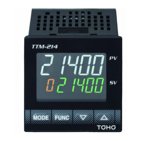
TOHO TTM-i4N User manual

1
Digital Controller
TTM‐i4N
User’s Manual
Contents
1. Precautions upon Usage 2
2. Name andFunction of Parts 4
3. Installation 5
3.1Dimensions 5
3.2Installation and Dimensions of Panel Cut 5
4. Wiring 6
4.1TerminalLayoutfor Wiring 6
4.2Caution upon Wiring 6
5. List of7-segment Characters 7
6. OperationFlow andParameters 8
6.1Display Sections 8
6.2Operation Keys 9
6.3Operation Flow 9
6.4Parameters 21
6.5OtherDisplays 69
7. List of Models 70
8. BeforePerforming a Control 71
9. Specifications 72
9.1General Specifications 72
9.2Rated Values and Performance 73
10. Maintenance and Inspection 74

2
1. Precautions upon Usage
Please read this section before use.
For the safe use of this product, please take note of the following:
This operation manual should be kept by the user of this product.
★Safety Precautions
For the safe use of the product and to prevent possible accident or damage, the following warning signs are used in this
operation manual depending on their level of importance and risk. Please follow each instruction in order for you to
use the product safely.
★Warning Symbols and Their Meanings
Danger Improper handling of the
equipment may cause fatality or
serious injury for an impending
reality. Caution Improper handling of the
equipment may cause injury
or physical damage on it.
Warning
Improper handling of the
equipment may cause fatality or
serious injury. Reminder
Care should be taken for
ensuring safety.
Matters that are indicated as “Caution” can also turn into serious accidents, depending on thesituation.
Please follow all instructions described herein for the safe use of this product.
★Example of Symbols
General caution, warning or
prohibition without
particularity
Instruction on ground
connection for the
equipment with safety
grounding terminals
Hazard of pinched fingers
on a particular portion of the
equipment
Possible injury caused by
touching a particular portion
of the equipment under
specific conditions
Unspecific behaviors of
general users
Hazard of injury due to high
temperature under specific
conditions
Hazard of an electric shock
under specific conditions
Hazard of injury such as an
electric shock due to
disassembling or
modification of the
equipment
Hazard of burst under
particular conditions

3
Warning
Improper wiring to the equipment may cause a failure, such as fire. Upon completion of wiring,
ensure to verify the proper wiring before turning on electricity.
Do not turn on electricity until all wiring is complete. Do not touch portions of high voltages such as
power supply terminals, as an electric shock may be resultant.
Install appropriate protective circuits externally if a failure or abnormality of the equipment may seriously affect
related systems.
Do not use the equipment out of the specified range, as it may fail or catch fire.
Do not under any circumstance to modify or disassemble the equipment, as a failure may be caused, resulting
fire or an electric shock.
Do not use the equipment in ambience of flammable or explosive gases.
Caution
Do not use the vacant terminals for wiring.
Do not use a pointed object to operate keys.
Do not turn on the power supply until wiring is fully complete in order to prevent an electric shock,
failure or malfunctioning. For replacing a component connected on the equipment, ensure to turn off
the power supply. For turning back on the power supply, do so after all wiring is complete.
Ensure not to trap heat in the space surrounding the equipment in order to provide sufficient heat release.
Do not put a metal piece or similar inside the equipment. A fire, an electric shock or failure may be caused.
The equipment is designed for instrumentation. For its use in environments of high voltages or intense noises,
take appropriate measures on the side of user’s equipment.
The equipment is designed for controlling physical values, such as temperatures, on general industrial facilities.
Do not use it for subjects of control that may seriously affect human life.
Turn off the power supply before cleaning the equipment, and wipe it with a soft dry cloth. Do not use
thinners, as they may cause deformation or discoloration of the equipment.
The equipment may cause radio disturbances in domestic settings. User is required to take appropriate
measure.
Ensure to tighten terminal screws at specified torque. Insufficient tightening the screws may cause an electric
shock or fire.
Ensure to observe precautions listed in this manual for the use of the equipment.
Reprinting or duplicating this manual is prohibited.
This manual may be revised without prior notice.
Important Reminder Regarding Export Trade Control Order
Please investigate the client and the purpose of his or her usage to make sure that the product will not be used as a weapon of
mass destruction (e.g., for military purposes and use in military facilities).

4
2. Name andFunction of Parts
PV
Displays the character of current measurement value or setting mode screen.
SV
Displays the selected input value of setting value, output value, or setting mode
screen.
°F
Lights up when the setting value is a temperature data with the unit of °F.
°C
Lights up when the setting value is a temperature data with the unit of °C.
RDY
Lights up when the control mode is RDY (ready).
OUT
Lights up when OUT1 (Output 1) is turned ON.
AL1
Lights up when Event Output 1 isturned ON.
AL2 Lights up when Event Output 2 is turned ON.
If heat/cool control is selected, it also lights up when OUT2 is turned ON.
M Key
Switches screens.
F Key
Executes functions that are being set.
▲▼keys Increases or decreases (to change) the setting value.
(Pressing each key continuously will increase/decrease the value more quickly.)

5
3. Installation
3.1 Dimensions
3.2 Installation and Dimensions of Panel Cut
Attach the product either vertically (upper surface of the product should be facing up) or horizontally.
How to Attach: Place the product into an angle hole of the panel cut and completely insert the attachment from the surface
without any gap.
63

6
4. Wiring
4.1 Terminal Layout for Wiring
4.2 Caution upon Wiring
Warning:TurnthepowerOFFbeforewiringtoavoidtheriskofelectricshock.
Caution:This product will not perform any control for approximately 4 seconds after turning its power ON
(producesnooutput).Pleasebecarefulifyouwillbeusingthisproductasaninterlockcircuit.
・Check the wiring with the operation manual to makesurethat input terminal, power terminal,option terminal, and other
suchterminalsareconnectedcorrectly.
・Uponwiring,usethecrimpedterminalthat fitswith theM3.5screw(squeezethewire intothecenter oftheterminal).
・For the connection between theresistancetemperature detectorand theproduct, use the wirewith theresistance of less
than 5Ω (per wire).
・For the connection between the thermocouple and the product, use the prescribed compensating lead wire or the wire
itself.
・Usetheradio shield wire if theproduct is to be usednear thenoise source. Donot wire the input-output line in the same
ductor conduittube.
・Separatetheinput-outputsignal linefrom bothpower and load lines with thedistanceof at least 50cm.
・Donotconnectanythingto theblankterminal.

7
5. List of 7-segment Characters
< List of 7-segment Characters >
Numbers and alphabets used in parameter symbols and settings are described as follows:
0
1
2
3
4
5
6
7
8
9
A
B
C
D
E
F
G
H
I
J
K
L
M
N
O
P
Q
R
S
T
U
V
W
X
Y
Z
−
Blank

8
6. Operation Flow andParameters
6.1 Display Sections
Display Sections
Color
Description
PV Display Section
White
• Displays measurement values and characters that have been set.
SV Display Section
Green
• Displays setting values and manipulated variables.
°F
Yellow
• Lights up when the setting value is a temperature data with the unit
of °F.
°C
Yellow
• Lights up when the setting value is a temperature data with the unit
of °C.
RDY Display
Yellow
• Lights up when the control mode is RDY.
OUT Display
Yellow
• Lights up when OUT1 is turned ON.
AL1 Display
Yellow
• Lights up when Event 1 Output is turned ON.
AL2 Display
Yellow
• Lights up when Event 2 Output is turned ON.
If heat/cool control is selected, it also lights up when OUT2 is turned ON.

9
6.2 Operation Keys
Operation Keys
Description
M Key
• Switches screens.
F Key
• Executes functions that are being set.
1) Digit Navigation Key (selected digit blinks): Usable in allmodes.
2) RUN/READY Key: Usable only in operation mode. Click once to enable the function.
3) AT Start/Stop Key: Usable only in operation mode. Click once to enable the function.
4) Timer Start/Reset Key: Usable only in operation mode. Click once to enable the
function.
5) Alarm Reset Key: Usable only in operation mode. Click once to enable the function.
6) ENTER Key: Usable in all modes.
DOWN Key
• Decreases the setting value.
(Pressed consecutively for 0.5–5secs.: 1 digit/100msecs.)
(Pressed consecutively for 5–10secs.: 10 digits/100msecs.)
(Pressed consecutively for more than 10secs.: 100 digits/100msecs.)
UP Key
• Increases the setting value.
(Pressed consecutively for 0.5–5secs.: 1 digit/100msecs.)
(Pressed consecutively for 5–10secs.: 10 digits/100msecs.)
(Pressed consecutively for more than 10secs.: 100 digits/100msecs.)
6.3 Operation Flow

10
6.3.1 Operation Mode
PV
SV
1200 1. Controlled Temperature Setting
0
↓M Key
PV
SV
****
2. Priority Screen 1
****
↓M Key
PV
SV
****
3. Priority Screen 2
****
↓M Key
PV
SV
****
4. Priority Screen 3
****
↓M Key
PV
SV
****
5. Priority Screen 4
****
↓M Key
PV
SV
****
6. Priority Screen 5
****
↓M Key
PV
SV
****
7. Priority Screen 6
****
↓M Key
PV
SV
****
8. Priority Screen 7
****
↓M Key
PV
SV
****
9. Priority Screen 8
****
↓M Key
PV
SV
****
10. Priority Screen 9
****
↓M Key
Back to 1.

11
6.3.2 Protect Setting Mode
PV
SV
PTLV
1.
Protect Level Setting
0
6.3.3 Priority Screen Parameter Mode
PV
SV
SET0
1. Setting Mode Selection Screen
PRI
↓M Key
PV
SV
PRI1
2. Priority screen 1 setting
OFF
↓M Key
PV
SV
PRI2
3. Priority screen 2 setting
OFF
↓M Key
PV
SV
PRI3
4. Priority screen 3 setting
OFF
↓M Key
PV
SV
PRI4
5. Priority screen 4 setting
OFF
↓M Key
PV
SV
PRI5
6. Priority screen 5 setting
OFF
↓M Key
PV
SV
PRI6
7. Priority screen 6 setting
OFF
↓M Key
PV
SV
PRI7
8. Priority screen 7 setting
OFF
↓M Key
PV
SV
PRI8
9. Priority screen 8 setting
OFF
↓M Key
PV
SV
PRI9
10. Priority screen 9 setting
OFF
↓M Key
Back to 1.

12
6.3.4 Input Parameter Mode
PV
SV
SET1
1. Setting Mode Selection Screen
INP
↓M Key
PV
SV
INP
2. Input type setting
00
↓M Key
PV
SV
PVG
3. PV compensation gain setting
100
↓M Key
PV
SV
PVS
4. PV compensation zero setting
0
↓M Key
PV
SV
PDF
5. Setting of Input Filter
00
↓M Key
PV
SV
DP
6. Decimal point setting
0
↓M Key
PV
SV
C/F
7. Temperature unit setting
*C
↓M Key
Back to 1.

13
6.3.5 Key Function Parameter Mode
PV
SV
SET2
1. Setting Mode Selection Screen
KEY
↓M Key
PV
SV
FU
2. Function key function setting
00
↓M Key
PV
SV
LOC
3. Key-lock setting
0
↓M Key
PV
SV
ALRS
4. Alarm reset
0 0
↓M Key
Back to 1.

14
6.3.6 Control Parameter Mode
PV
SV
SET3
1. Setting Mode Selection Screen
CNT
↓M Key
PV
SV
SLH
2. SV limiter upper limit
1200
↓M Key
PV
SV
SLL
3. SSV limiter lower limit
0
↓M Key
PV
SV
MD
4. Control mode setting
RUN
↓M Key
PV
SV
CNT
5. Control type setting
020
↓M Key
PV
SV
DIR
6. Tuning type setting
0
↓M Key
PV
SV
MV1
7. Manipulated Variable of Output 1
00
M key
PV
SV
TUN
8. Setting of Tuning Type
※1PV
SV
C1
19. Sensitivity setting for OUT1※2
1
1
↓M Key ↓M Key
PV
SV
ATG
9. AT coefficient setting
※1PV
SV
CP1
20. OFF point position setting for
OUT1※2
10
0
↓M Key MKey
PV
SV
ATC
10. AT sensitivity setting
※1
2
↓M Key
PV
SV
AT
11. AT start/stop
※1
OFF
↓M Key
PV
SV
P1
12. Proportional band setting for OUT1
※1
30
↓M Key
PV
SV
I
13. Integral time setting
※1
0
↓M Key

15
↓
PV
SV
D
14. Derivative time setting
※1
0
↓M Key
PV
SV
T1
15. Proportional cycle setting for OUT1
※1
20
↓M Key
PV
SV
ARW
16. Setting of Anti-reset Windup
※1
1100
↓M Key
PV
SV
MLH1
17. Operating amout limiter upper limit for OUT1
※1
1000
↓M Key
PV
SV
MLL1
18. Operating amout limiter lower limit for OUT1
※1
00
Mkey
PV
SV
LOP1
21. Setting of the Loop Abnormality Judgment Time of Output 1
0
↓M Key
PV
SV
PS1
22. Setting of the Loop Abnormality PV Variation of Output 1
※3
0
↓M Key
PV
SV
TS1
23. Setting of the Loop Abnormality PV Threshold of Output 1
※3
0
↓M Key
PV
SV
FDT1
24. Protection OFF timer time setting for OUT1
※2
0
↓M Key
PV
SV
NDT1
25. Protection ON timer timesetting for OUT1
※2
0
↓M Key
PV
SV
MV2
26. Manipulated Variable of Output 2
※4
00
Mkey
PV
SV
P2
27. Proportional band setting
for OUT2
※4 ※5
PV
SV
C2
31. Setting of the Sensitivity of Output
2
※4 ※6
100
1
↓M Key ↓M Key
PV
SV
T2
28. Proportional cycle setting
for OUT2
※4 ※5
PV
SV
CP2
32. OFF point position setting for
OUT2
※4 ※6
20
0
↓M Key ↓M Key

16
↓
PV
SV
MLH2
29. Operating amout limiter upper limit for OUT2
※4 ※5
1000
↓M Key
PV
SV
MLL2
30. Operating amout limiter lower limit for OUT2
※4 ※5
00
Mkey
PV
SV
LOP2
33. Setting of the Loop Abnormality Judgment Time of Output 2
※4
0
↓M Key
PV
SV
PS2
34. Setting of the Loop Abnormality PV Variation of Output 2
※4 ※7
0
↓M Key
PV
SV
TS2
35. Loop anormaly PV threshold for OUT2
※4 ※7
0
↓M Key
PV
SV
FDT2
36. Protection OFF timer time setting for OUT2
※6 ※4
0
↓M Key
PV
SV
NDT2
37. Protection ON timer timesetting for OUT2
※6 ※4
0
↓M Key
PV
SV
BMP
38. Enable/Disable Balance-less Bump-less Function
1
↓M Key
PV
SV
PBB
39. Manual reset setting
※1
00
↓M Key
PV
SV
DB
40. Dead band setting
※4
0
↓M Key
PV
SV
RMP
41. SV Ramp time setting
00
↓M Key
PV
SV
PWZ
42. Control backup function setting
※1
00
↓M Key
Back to 1.
※1 … This will not be displayed if the output type of Output 1 is ON/OFF control.
※2 … This will not be displayed if the output type of Output 1 is PID control.
※3 … This will not be displayed if the loop abnormality judgment time of Output 1 is “0.”
※4 … This will not be displayed if the output type of Output 2 is “None” or “Event 2 Output.”
※5 … This will not be displayed if the output type of Output 2 is ON/OFF control.
※6 … This will not be displayed if the output type of Output 2 is PID control.
※7 … This will not be displayed if the loop abnormality judgment time of Output 2 is “0.”

17
6.3.7 Event 1 Output Parameter Mode
PV
SV
SET4
1. Setting Mode Selection Screen
AL1
↓M Key
PV
SV
A1F1
2. Event 1 Function Setting 1
000
↓M Key
PV
SV
A1H
3. EV1 alarm upper limit setting
※8 ※9
0
↓M Key
PV
SV
A1L
4. EV1 alarm lower limit setting
※8 ※10
0
↓M Key
PV
SV
A1C
5. EV1 alarm sensitivity setting
※8
0
↓M Key
PV
SV
A1T
6. EV1 alarm delay timer setting
※11
0
↓M Key
PV
SV
A1F2
7. EV1 alarm function 2 setting
000
↓M Key
PV
SV
A1F3
8. EV1 alarm function 3 setting
00
↓M Key
PV
SV
A1P
9. EV1 alarm polarity setting
0
↓M Key
Back to 1.
※8… This will not bedisplayed if Event 1 function is turned OFF.
※9 … This will not be displayed if Event 1 function will not be used at the maximum limit.
※10 … This will not be displayed if Event 1 function will not be used at the minimum limit.
※11 … This will not be displayed if Event 1 functions 1 and 2 are turned OFF.

18
6.3.8 Event 2 Output Parameter Mode
PV
SV
SET5
1. Setting Mode Selection Screen
※12 ※13
AL2
↓M Key
PV
SV
A2F1
2. Event 2 Function Setting 1
※12
000
↓M Key
PV
SV
A2H
3. EV2 alarm upper limit setting
※12 ※14 ※15
0
↓M Key
PV
SV
A2L
4. EV2 alarm lower limit setting
※12 ※14 ※16
0
↓M Key
PV
SV
A2C
5. EV2 alarm sensitivity setting
※12 ※14
0
↓M Key
PV
SV
A2T
6. EV2 alarm delay timer setting
※12 ※17
0
↓M Key
PV
SV
A2F2
7. EV2 alarm function 2 setting
※12
000
↓M Key
PV
SV
A2F3
8. EV2 alarm function 3 setting
※12
00
↓M Key
PV
SV
A2P
9. EV2 alarm polarity setting
※12
0
↓M Key
Back to 1.
※12 … This willnot be displayed when themodel ofBoption is not specified.
※13 … This will not be displayed when the output type of Output 2 is other than “Event 2 Output.”
※14 … This will not be displayed when Event 2 function is set to “OFF.”
※15 … This will not be displayed when Event 2 function will not be used at the maximum limit.
※16 … This will not be displayed when Event 2 function will not be used at the minimum limit.
※17 … This will not be displayed when Event 2 functions 1 and 2 are set to “OFF.”

19
6.3.9 Timer Parameter Mode
PV
SV
SET6
1. Setting Mode Selection Screen
TIME
↓M Key
PV
SV
TMO
2. Timer output setting
0
↓M Key
PV
SV
TMF
3. Setting of Timer Function
※18
1
↓M Key
PV
SV
H/M
4. Setting of the Unit of Timer
※18
1
↓M Key
PV
SV
TSV
5. Setting of SV Start Permission Range
※18 ※19
0
↓M Key
PV
SV
TIM
6. Time setting
※18
00:00
↓M Key
PV
SV
TIA
7. Remaining time monitor
※18
00:00
↓M Key
Back to 1.
※18 … This will not be used when Timer Output is set to “Timer OFF.”
※19 … This willnot be displayed when Timer function isother than “SV Start.”

20
6.3.10 LCD Parameter Mode
PV
SV
SET7
1. Setting Mode Selection Screen
LCD
↓M Key
PV
SV
LLV
2. Brightness setting
100
↓M Key
PV
SV
LRFT
3. Dimming function setting
0
↓M Key
PV
SV
LRLV
4. Dimming Brightness setting
5
↓M Key
Back to 1.
Table of contents
Other TOHO Controllers manuals
Popular Controllers manuals by other brands
DaSeDa Electronics
DaSeDa Electronics HM-75A manual
RefPlus
RefPlus Guardian+ RC-F Programming manual

Delta Tau
Delta Tau PMAC Reference manual
Spectron
Spectron Spectrocem FE 121 user manual
CHAFFOTEAUX
CHAFFOTEAUX 3318597 Assembly and operation instructions
ADVATEK LIGHTING
ADVATEK LIGHTING PixLite 4 Mk2 ECO user manual
