Tol Watertechniek HD 200 User manual

Manual
Purusaqua
ORP controller

© Tol Watertechniek Page 2 10-1-2021
Dear Customer
We are honoured that you have chosen for the products of Tol WaterTechniek (hereinafter referred to
as TWT). Read this manual carefully so you will use the product correctly and so a correct functioning
is guaranteed. If after reading this manual or while using our product you have any questions, please
contact your dealer or TWT. We will be happy to help
!

© Tol Watertechniek Page 3 10-1-2021
Table of contents
Table of contents ........................................................................................................................ 3
1 EG declaration.................................................................................................................... 4
2 Safety.................................................................................................................................. 6
2.1 Intended scope............................................................................................................ 6
2.2 Risks in the use of ozone equipment.......................................................................... 6
3 Requirements regarding the installation environment........................................................ 7
4 ORP controller.................................................................................................................... 8
4.1 Explanation of the controls ........................................................................................ 8
4.2 Installing the ORP controller...................................................................................... 9
4.3 Checking the right connection of the ORP controller ................................................ 9
4.4 Setpoint and hysteresis ............................................................................................... 9
4.4.1 Adjusting the setpoint....................................................................................... 10
4.4.2 Setting the hysteresis........................................................................................ 10
4.5 Calibrating the controller ......................................................................................... 11
4.6 Maintenance ............................................................................................................. 12
4.7 Storing the electrode................................................................................................. 12
4.8 Problem solving........................................................................................................ 12
4.9 Technical data .......................................................................................................... 13
5 Miscellaneous peripherals ................................................................................................ 14
5.1 Flow-trough assembly .............................................................................................. 14
6 Warranty determination.................................................................................................... 15
7 Disclaimer ........................................................................................................................ 16
8 Contact information.......................................................................................................... 17
© Tol Watertechniek Page 4 10-1-2021
1 EG declaration
© Tol Watertechniek Page 5 10-1-2021

© Tol Watertechniek Page 6 10-1-2021
2 Safety
2.1 Intended scope
The products described in this manual are intended to be used for the treatment of slightly
contaminated water. Water of pools, ponds, aquariums and light industry or similar for example.
The use of these products in a different situation than recommended may result in personal injury and
possible premature wear of the equipment.
2.2 Risks in the use of measuring equipment
Despite the fact that our products are designed in such a way that the risks are minimalized there is
always a risk of dangerous situations. During the use of our measuring equipment various parts are
connected to the mains voltage. Never open the enclosure of our measuring equipment if the power
lead is still connected to the mains.

© Tol Watertechniek Page 7 10-1-2021
3 Requirements regarding the installation environment
Measuring equipment should be placed in a dry and cool environment protected against direct sunlight
and rain.
It is of great importance that the cable inlet of the electrode remains above water at all times.
Therefore it is preferred to use a flow trough assembly to mount the electrode . Electrodes are not
suited in systems operating under high pressure. The use is only permitted in places with a pressure
below 0.3 bar.
Defects caused by neglecting these installation requirements will not be covered by warranty!
© Tol Watertechniek Page 8 10-1-2021
4 ORP controller
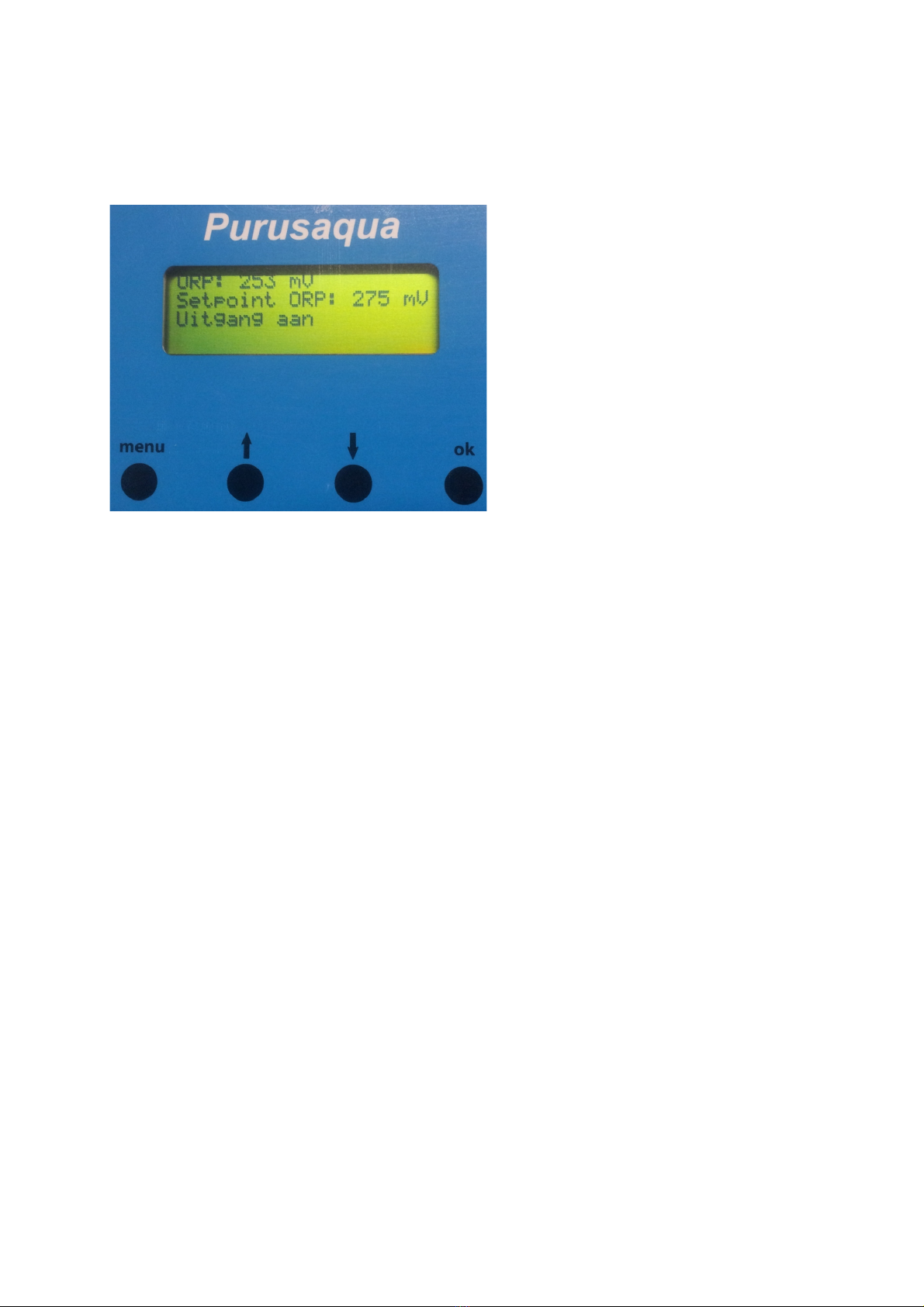
4.1 Explanation of the controls
Display (green screen)
On the display the measured values are shown such as the current ORP value, setpoint and the status
of the output. In the shown photo the "value screen" is shown.
Menu button
If the menu button is pressed while the value screen is shown the setting menu will be shown. In this
menu the controller can be calibrated and the parameters of the output can be set. If the menu button
is pressed a second time the display will show the value screen again.
↑Scroll button "up"
The up button is used to navigate through the menu and to adjust settings. The setpoint and
calibration parameters can be adjusted with this button.
↓Scroll button "down"
The down button is used to navigate through the menu and to adjust settings. The setpoint and
calibration parameters can be adjusted with this button.
Ok button
The Ok button is used to select a menu item or to confirm a setting.

© Tol Watertechniek Page 9 10-1-2021
4.2 Installing the ORP controller
Uninstall the lid by turning the 4 screws in the lid one quarter. De screws will pop up en are raised
above the lid. Now you can fold the lid open.
Mount the ORP controller on a flat surface in a dry environment en screw the lid
back in place. Only mount the ORP controller in a dry and well ventilated
environment protected from direct sunlight. Only connect the ORP controller to a
wall socket with a safety earth connection!
It is advised to use a flow trough assembly to mount the electrode (available by
your dealer).You can place the electrode in a sieve or vortex as well but be
careful that the wire connection on the electrode remains above the water level
at all time.
4.3 Checking the right connection of the ORP controller
There are a few simple tests which you could perform to test if the controller is connected right.
•Place your electrode in a glass of tap water, the controller should show a value between 150
and 300mV.
•Gently wipe your finger over the electrode tip, the shown value should change quite rapidly.
4.4 Setpoint and hysteresis
The ORP controller has an adjustable relay output. This can be used to control a dosing pump or a
ozone generator.
The value at which this relay should be controlled is referred to as "setpoint". You also can adjust the
hysteresis. The hysteresis prevents that the relay will flicker around its setpoint, below an example.
Assume that the setpoint is set to 275mV and the hysteresis is set to 5mV. As soon as the measured
value becomes below 270mV (setpoint - hysteresis) the relay will be activated. The measured value
need to be raised to 280mV (setpoint + hysteresis) to get deactivate.
At a hysteresis of 0mV the relay would be activated at a measured value below 275mV and
deactivated at a value higher as 275mV. Thus the relay would flicker around the setpoint of 275mV,
this is prevented by the hysteresis.
© Tol Watertechniek Page 10 10-1-2021
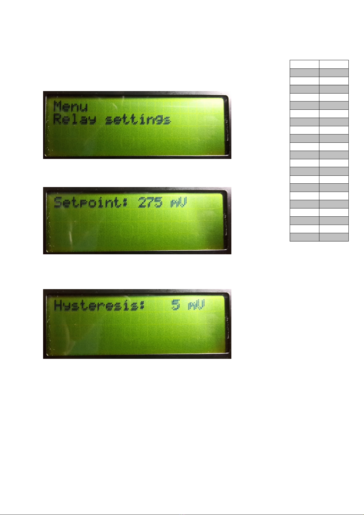
4.4.1 Adjusting the setpoint
We advice you to adjust the setpoint according to the table shown on this page. The
hysteresis is preset at 5mV in the factory, for most applications this is a good setting.
To adjust the setpoint press the menu button once, the screen below is shown:
Next press the "ok" to confirm that you want to adjust the setpoint. The following screen
appears which ask you to adjust the setpoint:
You can adjust the setpoint to the desired value by pressing the ↑and ↓buttons. If the setpoint is
adjusted to the desired value you must confirm the setting by pressing the "ok" button. The following
screen appears which ask you to set the hysteresis:
4.4.2 Setting the hysteresis
The hysteresis is set by pressing the ↑and ↓buttons. If the hysteresis is adjusted to the desired value
you need to confirm the setting by pressing the "ok" button. The setpoint and hysteresis are now set
and the display of the ORP controller now will show the menu again. By pressing the ↑and ↓buttons
you can scroll through the menu. By pressing the "menu" button the ORP controller will return to the
value screen.
pH
Max. mV
6
330
6,1
330
6,2
320
6,3
320
6,4
310
6,5
310
6,6
300
6,7
290
6,8
290
6,9
280
7
270
7,1
270
7,2
260
7,3
260
7,4
250
7,5
250
7,6
240
7,7
230
7,8
230
7,9
220
8
210
© Tol Watertechniek Page 11 10-1-2021
4.5 Calibrating the controller
In order to get reliable measuring data the ORP controller should be calibrated on a regular base (2 to
4 times a year). Before the ORP controller is used it should be calibrated too and also if you will
replace the electrode in the future. If you have bought this controller including an electrode the
controller will be calibrated for you in our factory before delivery.
To calibrate the ORP controller you need to walk through the following steps. Put the electrode in the
calibration fluid with the highest value. The tip of the electrode should be fully submersed in the
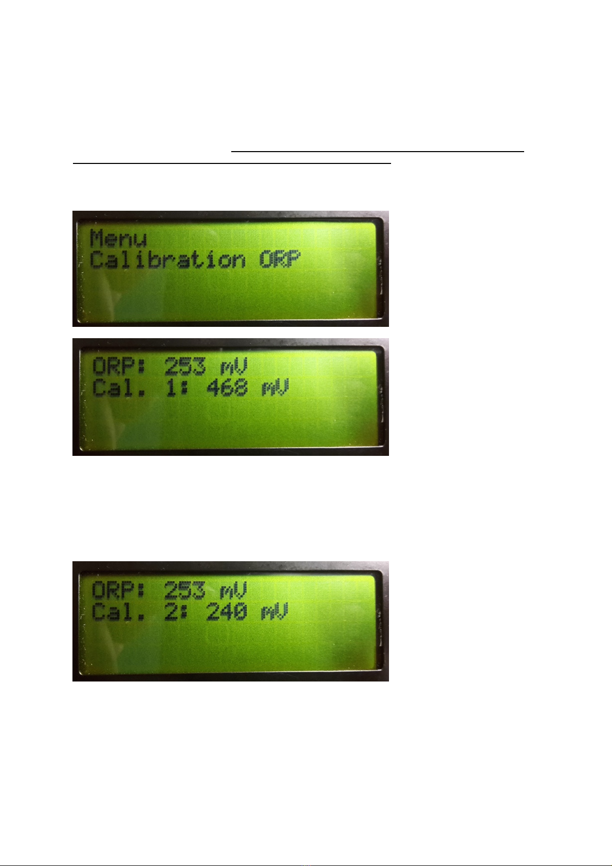
calibration fluid. Now press the "menu" button and once on the ↓button, the following screen is shown:
Press the "ok" button to confirm that you want to calibrate the controller. The next screen appears:
The upper value is the current value measured by the electrode. The bottom value is the value of the
calibration fluid. Wait for the upper value to stabilize, a fluctuation of 2mV within 10 second is
acceptable. By pressing the ↑and ↓buttons you should adjust the lower value so it corresponds with
the value shown on the bottle of calibration fluid. Now press the "ok" button to confirm the first
calibration parameter. In the shown example the value of the calibration fluid is 468mV.
After you pressed the "ok" button the following screen appears:
Rinse the tip of the electrode with tap water and shake of the drops of water. Now place the electrode
in the calibration fluid with the lowest value.
T
ake care again that the tip of the electrode is fully
submersed. Now wait for the upper value to stabilize, a fluctuation of 2mV within 10 second is
acceptable. By pressing the ↑and ↓buttons you should adjust the lower value so it corresponds with
the value shown on the bottle of calibration fluid. Now press the "ok" button to confirm the second
calibration parameter. In the shown example the value of the calibration fluid is 240mV.
By pressing the "menu" button the ORP controller will shown the value screen.

© Tol Watertechniek Page 12 10-1-2021
If you just have one type of calibration fluid then you perform both steps with the same calibration fluid.
The rinsing of the electrode in between the two calibration steps can be skipped. Be sure that if you
use only one calibration fluid that you set the Cal.1 and Cal.2 values exactly the same!
This is a so called "one point calibration" which is less accurate a standard "two point" calibration.
If the calibration procedure is aborted before completion your ORP controller will not function
properly, so always perform a complete calibration procedure!
4.6 Maintenance
The maintenance of the controller exists out of cleaning the enclosure with a damp cloth. The
electrode should be cleaned every 2 to 4 weeks, the interval deepens on the situation and application.
The best way to do this is to gently wipe the electrode tip with your fingers. Never use brushes or
clothes!
4.7 Storing the electrode
Never store the electrode dry, this will damage the electrode within hours. To store the electrode just
fill the delivered storage bottle with water to about 1/3. Put the electrode in the bottle and take care
that the tip of the electrode is submerged.
4.8 Problem solving
The display stays blank:
•Check if the mains cable is connected to a working wall socket.
•Check the fuse and replace with a fuse with the same value if necessary (the fuse is located
inside the controller on the printed circuit board) Be sure to disconnect the controller from
the mains before opening the housing!
The ORP controller doesn't switch off the ozone generator if the measured value is above the
setpoint:
•Check if the setpoint is set correctly and if the hysteresis is set to the correct value.
The ORP controller doesn't switch on the ozone generator if the measured value is below the
setpoint:
•Check if the setpoint is set correctly and if the hysteresis is set to the correct value.
The first line of the display shows "ORP out of range L" or "ORP out of range H":
•The measured signal is above 1000mV (H) or below -1000mV (L). Replace the electrode.
The measured value shown on the display is unstable:
•Check if the electrode if submersed and placed in flowing water.
•Check if the cable inlet of the electrode is above the water level.
•Rinse or replace the electrode.
•Check if there is interfering equipment near the controller or electrode such as: frequency
converters, adjustable water pumps, TL lighting, UV lamps with electronic ballasts, etc.
The measured value hardly changes:
•Check if the electrode if submersed and placed in flowing water.
•Check if the cable inlet of the electrode is above the water level.
•Rinse or replace the electrode.

© Tol Watertechniek Page 13 10-1-2021
4.9 Technical data
RC2304
Max switching power 600 watt (resistive)
Electrode connection BNC
Measuring range -999 tot 999 mV
Setpoint range -999 tot 999 mV
Hysteresis range 1 to 50 mV
Resolution (accuracy displayed value) 1mV
Deviation +/- 5mV
Voltage 230V 50Hz
Relay 1x NC/NO
Length 200 mm
Width 150 mm
Height 115 mm
© Tol Watertechniek Page 14 10-1-2021
5 Miscellaneous peripherals
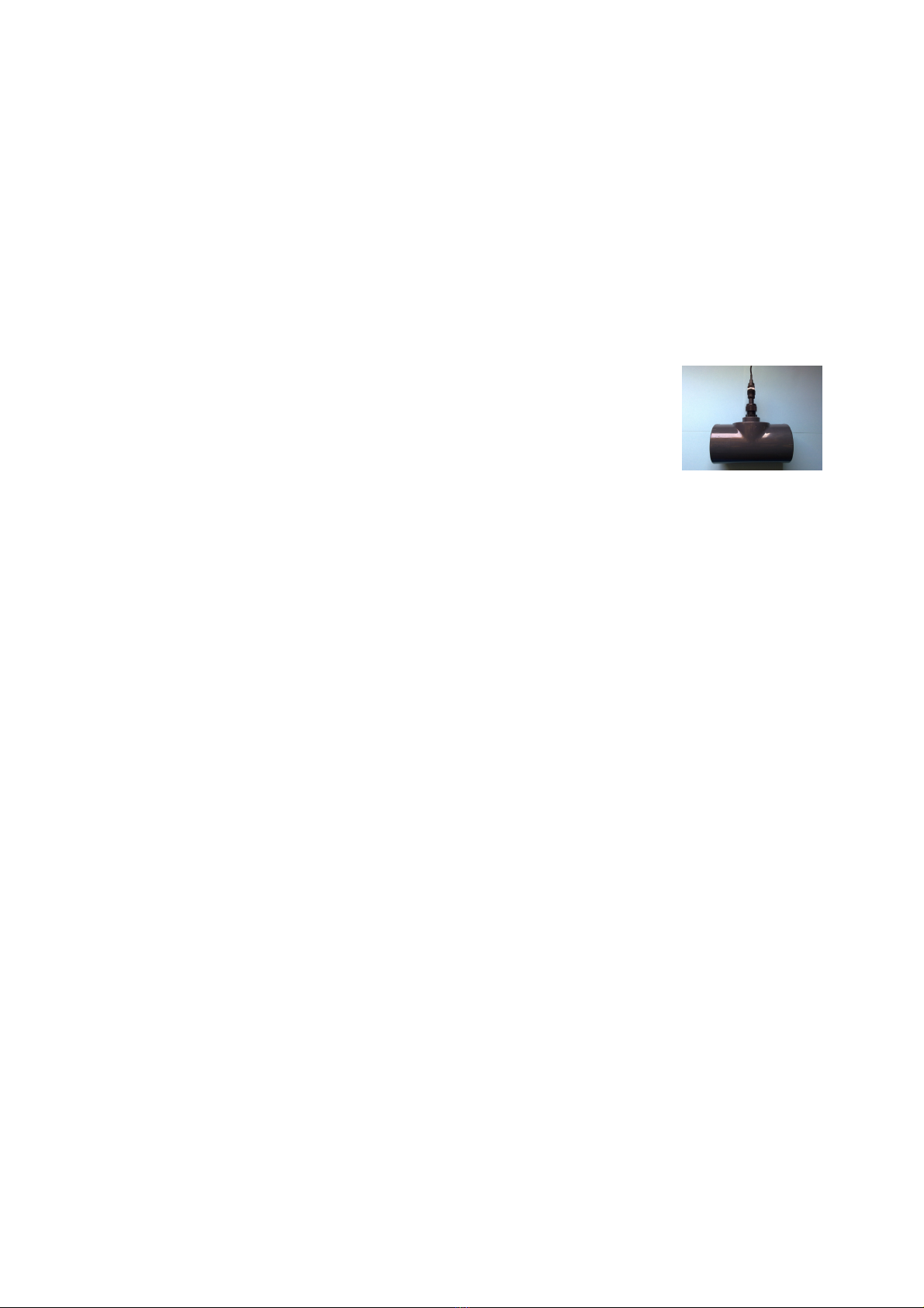
5.1 Flow-trough assembly
For a proper ORP measurement it is important that the electrode is located in a proper water flow. By
the use of a flow-through assembly you can be sure that the electrode is placed in sufficient flow, and
that it can not submerged.
There must be placed a straight piece of piping before and after the flow-trough assembly. There must
be at least a piece of pipe of 4x the pipe diameter before and after it. At a diameter of 50mm this
means that there must be a piece of pipe of 20cm before and after the flow
trough
assembly.
A flow trough assembly must be placed at the water inlet of the ozone reactor.
Loosen the nut of the gland so that the electrode can be placed in the gland.
Positioning the electrode in such a way that the probe (end of the electrode) is in
the middle of the flow-trough assembly. Now tighten the nut by hand so that the
electrode is fixed.

© Tol Watertechniek Page 15 10-1-2021
6 Warranty determination
Our products come with one year warranty, defects caused by the manufacturing process within the
warranty period will be repaired free of charge. The following aspects are not covered by the
guarantee. Defects in our products caused by:
General
•not following the guidelines given in this manual.
•incidents or deliberate destruction of the product.
•changes made to the products by the customer.
•natural disasters such as floods, hurricanes, etc.
•not able to submit purchase bill or warranty bill.
•placing the product in a non suited environment (direct sunlight, rain, etc)
ORP controllers
•overload
•by replacing the fuse by a fuse of a different value.
•damage caused by placing the controller in an excessively damp environment.
Electrodes
•cleaning the electrode with chemicals.
•damaging the electrode tip.
•immersion of the whole electrode.
•the use of electrodes in liquids other then clean water.
•entry of foreign liquids in the electrode.
•dry storage of the electrode.
The cost for sending the product to the service point are for the customer. If the repair is under
warranty, the costs for returning the goods are on our behalf. In all other cases, all shipping costs must
be paid by the customer. TWT and its dealers are not responsible for damage caused by the use of
our products.

© Tol Watertechniek Page 16 10-1-2021
7 Disclaimer
TWT has written this manual with advice to the best of intentions. However, TWT does not accept any
liability with regard to this manual, nor for the application of our products in whatever form or nature
whatsoever.
The copyright of this document belongs to TWT. It is forbidden to modify this manual or to copy (parts
of) this manual in any way without the written consent of TWT. Copyright infringement will be
contested in any way possible.
TWT reserves the right to change the information in this manual without prior notice. All photos in this
manual are designed to serve as explanation element, the pictures may differ from the real product.

© Tol Watertechniek Page 17 10-1-2021
8 Contact information
Tol Watertechniek
Veldhuisweg 4
8372VH Baarlo (Ov.)
The Netherlands
Telephone: +31 (0) 6-12454088
Email: info@tolwatertechniek.nl
Chamber of commerce number: 05086435
VAT number: NL002153056B65
This manual suits for next models
4
Table of contents


