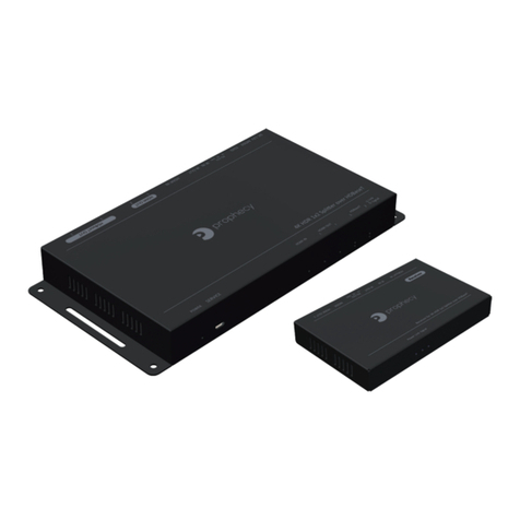
gofanco PRO-HDBaseT4P User manual

PRO-HDBaseT4P
PRO-HDBaseT4P-RX
X3
1x4 4K-HDR HDMI Splier over Single Cat.x with
HDBaseT-Lite, IR, RS-232, PoC & Loopout
®
Made in Taiwan
User‘s Guide

®
PRO-HDBaseT4P
Congratulaons for owning a gofanco product. Our products aim to meet all your
connecvity needs wherever you go.
Have fun with our products!
Please read this manual carefully before rst use.
If you need more informaon about our products, please visit www.gofanco.com.
For technical support, please email us at support@gofanco.com.
For drivers/manuals download, please go to hp://www.gofanco.com/download.

®
PRO-HDBaseT4P
Please read all of these instructions carefully before you use the device. Save
this manual for future reference.
The PRO-HDBaseT4P 1x4 4K-HDR HDMI Splitter over Single Cat.x with HDBa-
seT-Lite, IR, RS-232, PoC & Loopout has been tested for conformance to safety
regulations and requirements, and has been certied for international use. Ho-
wever, like all electronic equipments, the PRO-HDBaseT4P should be used with
care. Please read and follow the safety instructions to protect yourself from
possible injury and to minimize the risk of damage to the unit.
• Follow all instructions and warnings marked on this unit.
• Do not attempt to service this unit yourself, except where explained in this
manual.
• Provide proper ventilation and air circulation and do not use near water.
• Keep objects that might damage the device and assure that the placement of
this unit is on a stable surface.
• Use only the power adapter and power cords and connection cables designed
for this unit.
• Do not use liquid or aerosol cleaners to clean this unit. Always unplug the po-
wer to the device before cleaning.
1. Safety and Notice
Table of Contents
1. Safety and Notice ..................................................................3
2. Introduction .......................................................................4
3. Features...........................................................................4
4. Package Contents ..................................................................5
5. Specication ......................................................................6
6. Panel Description ..................................................................7
7. Connection Diagram ..............................................................10
8. IR Pass-Through...................................................................11
9. Notice............................................................................12
10. LearningWarranty ................................................................14
3

®
PRO-HDBaseT4P
• HDMI 2.0a compliant
• Supports 4K2K@60 4:4:4 8bits
• Supports HDR*, which is 4K2K@60 4:2:0 10bits**
• Extends HDMI signal up to 60m (198ft) at Full HD 1080p 36-bit, 35m
(114ft) at 4K2K@60 444 & 4K HDR
• Supports PoC (Power over Cable) which allows all Receivers to be powe-
red by the Transmitter with just one power adapter
• Supports two HDMI loopouts
• HDCP 2.2/1.4 support
• Supports resolution downscaling from 4K2K to 1080P*
• Supports EDID management
• Auto equalization
• Pure unaltered uncompressed 7.1ch digital HDMI over Cat.5/5e/6 cable
transmission
• DTS-HD Master Audio and Dolby TrueHD high bit rate audio support
3. Features
The PRO-HDBaseT4P 1x4 4K-HDR HDMI Splitter over Single Cat.x with
HDBaseT-Lite, IR, RS-232, PoC & Loopout provides the most cost eective
and advanced HDMI splitter solution on the market, by which the high de-
nition video and high quality audio can be transmitted up to 10 dierent
locations without losing quality. PRO-HDBaseT4P supports all 3D formats,
the true 4K 2K video and provides two HDMI local loopouts. In addition,
PRO-HDBaseT4P is also equipped with bi-directional IR pass-through path
and RS-232 serial port control.
With built-in USB rmware update mechanism, the compatibility among
countless HDMI sources and receivers can be further guaranteed. With
the upmost 12 bit deep color video and high denition audio support,
PRO-HDBaseT4P is suitable for high quality HDMI broadcasting, digital sig-
nage and education applications!
2. Introduction
4

®
PRO-HDBaseT4P
• 1x PRO-HDBaseT4P
• 3x PRO-HDBaseT4P-RX
• 1x DC 12V 7.5A
• 1x 3-pin Terminal Block Connector
• 1x IR Blaster
• 3x IR Receiver
• 1x User Manual
4. Package Contents
5
• Supports full frequency IR signal from 30KHz to 56KHz
• Bi-directional IR path-through
• RS-232 Pass-Thru: Up to 115,200bps
• Video latency less than 20 us.
• Easy installation
HDR = High Dynamic Range.
The video bandwidth of 4K2K@60 4:2:0 10bits (HDR) is 384 MHz, and the
4K2K@60 4:4:4 8bits is 594MHz.
(a) the PRO-HDBaseT4P can support resoluon downscaling from 4K2K to 1080P
(b) Does not support resoluon downscaling from 4K2K@60 4:2:2 to 1080P
(c) Does not support frame rate conversion
*
**
!
When used in conjunction with the PRO-HDBaseT4P-RX receiver

®
PRO-HDBaseT4P
5.Specications
Item Description
Technical
Role of usage 1x4 Distribution Amplier (Splitter)
HDMI compliance HDMI 2.0a
HDCP compliance Yes
Video bandwidth Single-link 600MHz [18Gbps]
Video support HDR 4K2K@60(4:2:0 10bits)/ 4K2K@60 (4:4:4 8bits)
Transmission over
UTP cable
1080p@60 60m (198ft) [CAT5e]
4K2K@60 (4:4:4 8bit) 35m (114ft) [CAT5e]
ESD protection Human body model — ±15kV [air-gap discharge] & ±8kV [contact discharge]
Audio support Surround sound (up to 7.1ch) or stereo digital audio
Input TMDS signal 1.2 Volts [peak-to-peak]
Input DDC signal 5 Volts [peak-to-peak, TTL]
PCB stack-up 4-layer board [impedance control — dierential 100Ω; single 50Ω]
Input 1x HDMI/ 1x 3.5mm
Output 2x HDMI/ 4x RJ-45[HDBaseT]/ 1x 3.5mm
IN/ OUT 1x RS-232
HDMI source control Controllable via IR pass-through from RX to TX with IR extenders
HDMI connector Type A [19-pin female]
RJ-45 connector WE/SS 8P8C(Reverse Mode)
Rotary switch Yes
3.5mm connector IR receiver / IR blaster
Mechanical
Housing Metal enclosure
Dimensions
[L x D x H]
Model 328 x 150 x 27mm [1' x 5.9" x 1"]
Package 524 x 265 x 76 mm [1'7" x 10.4" x 3"]
Carton 542 x 411 x 300 mm [1'8" x 1'3" x 11.8"]
Weight Model 1380g [3 lbs]]
Package 2207g[4.9 lbs]
Fixedness 1RU rack-mounting case with ears
Power supply 12V 7.5A DC
Power consumption 55 Watts [max]
Operation temperature 0~40°C [32~104°F]
Storage temperature -20~60°C [-4~140°F]
Relative humidity 20~90% RH [no condensation]
6

®
PRO-HDBaseT4P
6. Panel Description
Front Panel
Rear Panel
1. Power LED: Power indicator
2. Micro-USB: For technical support only [rmware update]
3. HDMI Signal LED: Input, Loopout 1, Loopout 2 (from left to right)
4. Link Receiver LED: Link LED indicator 1-4
5. HDMI Signal LED at Receiver: Output signal LED indicator 1-4
6. +12V DC: Connect to the +12V 7.5A power supply unit
7. EDID Management Rotary control:
7
1 2
6 7 8 9
10 1511 12 13 14
5
43
8. RS-232(terminal block format): The order of RS-232 pin are TX, RX, GND
(from the left side to the right)
9. IR Blaster:
Infrared 3.5mm socket for plugging in the extension cable of IR blaster
MODE 0 Ultra HD(4K2K@60) – 8/10/12bit 3D HDR video & 7.1ch audio
MODE 1 Ultra HD(4K2K@60) – 8/10/12bit 3D HDR video & 2ch audio
MODE 2 Ultra HD(4K2K@30)(4K2K@60 420) – 8/10/12bit 3D HDR video & 7.1ch audio
MODE 3 Ultra HD(4K2K@30)(4K2K@60 420) – 8/10/12bit 3D HDR video & 2ch audio
MODE 4 Full-HD(1080p@60) – 12bit 3D video & 7.1ch audio
MODE 5 Full HD(1080p@60) – 8bit 2D video & 2ch audio
MODE 6 Learning EDID from loopout #1
MODE 7 Auto EDID analysis learning mode
PRO-HDBaseT4P

®
PRO-HDBaseT4P
10. IR Receiver:
Infrared 3.5mm socket for plugging in the extension cable of IR receiver
11. HDMI IN: Connect to a HDMI input source
12. HDMI LOOPOUT #1:
Connect to a HDMI display with a HDMI male-male cable here
13. HDMI LOOPOUT #2:
Connect to a HDMI display with a HDMI male-male cable here
14. HDMI Signal OUT1-4: Link to each HDMI display via a Cat-5/5e/6 cable with a
HDMI over Cat.X receiver.
15. Ethernet Port
8

®
PRO-HDBaseT4P
9
PRO-HDBaseT4P-RX
1. Micro-USB: For technical support only [rmware update]
2. HDMI Signal LED: Output #1 signal LED indicator
3. HDMI Signal LED: Output #2 signal LED indicator
4. Power LED: Power indicator LED
5. Link LED: Link indicator LED
6. Signal LED: When receiving unit receive the HDMI signal, the LED light will shine
Front Panel
Rear Panel
54321 6
Position If setting
PIN#1 OFF[]Reserved
ON[]Reserved
PIN#2 PIN#3
OFF[]OFF[]RS-232 normal use
OFF[]ON[]Reserved
ON[]OFF[]For system rmware update
ON[]ON[]For HDBaseT rmware update
1 2 3 4
OFF
ON
7. RJ45: Plug in a Cat-5/5e/6 cable that needs to be linked to the transmitting unit
8. IR Receiver:
Infrared 3.5mm socket for plugging in the extension cable of IR receiver
9. IR Blaster:
Infrared 3.5mm socket for plugging in the extension cable of IR blaster
10. RS-232(terminal block format): The order of RS-232 pin are TX, RX, GND
(from left to right)
11. Dip Switch: for F/W update
7 8 9
10 11 12 13
12. HDMI OUT #1: Connects to a HDMI display with HDMI male-male cable
13. HDMI OUT #2: Connects to a HDMI display with HDMI male-male cable

®
PRO-HDBaseT4P
10
7. Connection Diagram

®
PRO-HDBaseT4P
11
i
8. IR Pass-Through
IR Extenders
IR Sockets
IR Blaster IR Receiver
IR BLASTER:
plug in the IR blaster to emit all IR command signals received from the IR receiver from the
other end to control the devices corresponding to the IR signals.
IR RECEIVER:
plug in the IR receiver to receive all IR command signals from the IR remote controls of the
corresponding devices.
CAUTION
Incorrect placement of IR Blaster and Receiver may result in the failure of the
IR extenders. Please check carefully before plugging in the IR extender to the
respective IR sockets. Warranty will not cover the damage.
DenitionofIREarphoneJack
IR Blaster IR Receiver
You can buy any IR extension cables in the market that are compatible to
the definition of the IR sockets for the matrix if necessary for replacement
use. However, IR cables longer than 2m (6-ft) may not work.

®
PRO-HDBaseT4P
12
1. Short blackout periods are expected when new monitors are connected to
the splitter. The splitter will do Automatic EDID learning which analyzes the
newly connected monitor to see if the EDID for the HDMI input is necessary
to update!
2. Firmware update is proceed through Micro-USB
9. Notice
Main Board
(1)Power on the device
(2)Connect the Micro-USB cable between PC and device
(3)Open rmware update software
(4)Set the correct COM port and DO NOT click button
(5)Click the button to open the Firmware Update Tool window
(6)Click the button to select the main board rmware le
(7)Click the button and the rmware will start to update
(8)After updating, please power cycle the device

®
PRO-HDBaseT4P
13
Output
(1)Power on the device
(2)Connect the Micro-USB cable between PC and device
(3)Open firmware update software
(4)Set the correct COM port and click button to connect software
(5)Click the button to open the FW Update window
(6)Click the button to select the output firmware file
(7)Click the button and the firmware will start to update
(8)After updating, please power cycle the device
Input
(1)Power on the device
(2)Connect the Micro-USB cable between PC and device
(3)Open rmware update software
(4)Set the correct COM port and click button to connect software
(5)Click the button to open the software folder
(6)Save the rmware le in this software folder and reconnect the Micro-USB cable
(7)Open rmware update software and then device will start to update rmware
automatically
(8)After update process is done, software will show “Success” message and then
be closed automatically
(9)After updating, please power cycle the device

®
PRO-HDBaseT4P
14
10. Limited Warranty
The SELLER warrants the PRO-HDBaseT4P 1x4 4K-HDR HDMI Splitter over Sing-
le Cat.x with HDBaseT-Lite, IR, RS-232, PoC & Loopout free from defects in the
material and workmanship for 1 year from the date of purchase from the SELLER
or an authorized dealer. Should this product fail to be in good working order wi-
thin 1 year warranty period, The SELLER, at its option, repair or replace the unit,
provided that the unit has not been subjected to accident, disaster, abuse or any
unauthorized modications including static discharge and power surge. This
warranty is oered by the SELLER for its BUYER with direct transaction only. This
warranty is void if the warranty seal on the metal housing is broken.
Unit that fails under conditions other than those covered will be repaired at the
current price of parts and labor in eect at the time of repair. Such repairs are
warranted for 90 days from the day of reshipment to the BUYER. If the unit is
delivered by mail, customers agree to insure the unit or assume the risk of loss
or damage in transit. Under no circumstances will a unit be accepted without a
return authorization number.
The warranty is in lieu of all other warranties expressed or implied, including
without limitations, any other implied warranty or tness or merchantability for
any particular purpose, all of which are expressly disclaimed.
Proof of sale may be required in order to claim warranty. Customers outside
Taiwan are responsible for shipping charges to and from the SELLER. Cables and
power adapters are limited to a 30 day warranty and must be free from any mar-
kings, scratches, and neatly coiled.
The content of this manual has been carefully checked and is believed to be
accurate. However, The SELLER assumes no responsibility for any inaccuracies
that may be contained in this manual. The SELLER will NOT be liable for direct,
indirect, incidental, special, or consequential damages resulting from any defect
or omission in this manual, even if advised of the possibility of such damages.
Also, the technical information contained herein regarding the PRO-HDBa-
seT4Pfeaturesandspecicationsissubjecttochangewithoutfurthernotice.

The product name and brand name may be registered trademarks of related manufacturers. TM and ®
may be omied on the user‘s guide. The pictures on the user‘s guide are just for reference, and there
may be some slight dierences with the actual products.
We reserve the rights to make changes without prior noce to a product or system described herein to
improve reliability, funcon, or design.
Disclaimer

Thank you for choosing gofanco
®
www.gofanco.com
Mar, 2019 Ver. A Copyright © by gofanco, LLC. All rights reserved.
This manual suits for next models
1
Table of contents
Other gofanco Cables And Connectors manuals

gofanco
gofanco PRO-HDRsplit2P User manual

gofanco
gofanco prophecy PRO-HDBaseT2P User manual

gofanco
gofanco PRO-HDRsplit2P-LT User manual

gofanco
gofanco Prophecy PRO-MSTmDP2HD User manual

gofanco
gofanco PRO-HDRsplit4P User manual

gofanco
gofanco PRO-HDRsplit4P-LT User manual

gofanco
gofanco HDSplit24 User manual

gofanco
gofanco DPMST2HDMI User manual

gofanco
gofanco DPMSTHub User manual

gofanco
gofanco Splitter2P User manual