Tomberlin E-MERGE Installation guide

Page 1
Tomberlin Technical Training
4-Wheel Braking System Level 2
This training provides instructions on how to diagnose, inspect, repair, bleed, and adjust the Tomberlin E-MERGE 4-wheel
braking system.
Brake Diagnostics and Inspection
The Tomberlin E-MERGE braking system should be inspected anytime there is a perceived or actual reduction in braking
performance. Indicators, possible causes, what to inspect and repairs are outlined below.
Indicator
Possible Cause
Fix
“Softer”
brake
pedal
Air in the hydraulic system due to
loss of fluid and/or intake of air.
Air must be removed via bleeding. See the section on how to bleed the
braking system.
Accumulation of braking fluid on
ground, hydraulic joints,
inside/outside drums
accompanied by lower fluid level
in the master cylinder.
Inspect, clean and tighten joints where braking fluid has accumulated.
Fill the master cylinder with DOT 3 brake fluid to the proper level. Test
brakes and reinspect the joints. If no additional fluid is found bleed the
system if necessary.
Breakage of brake lines, rusted or
loose connectors, bleeders, etc.
Inspect all components from the master cylinder to each wheel. See the
next section on visual brake inspection instructions. Replace
broken/damaged parts, fill the brake fluid in the master cylinder and
bleed the system.
Disk pads or drum shoes worn
Inspect and replace pads/shoes if worn out.
Master cylinder
After the above have been inspected and fixed—and softness still
exists—it could be a bad master cylinder. Inspect/replace if necessary.
Brake fluid contamination
DOT 3 brake fluid is clear or slightly tinted. Brake fluid is contaminated
when discolored, or has a swirl type pattern in it (possibly mixed with
oil), foreign debris, rust, etc. The reason for contamination must be
identified, repaired, and fluid must be replaced.
Grinding
noise
when
brakes
applied
Worn out disk pads will cause a
grinding/growling noise.
Note: Due to the majority of braking performed by the disk brakes, they
are more likely to wear out before the drum shoes. There is no wear
indicator tab on the disk pads. Replace the pads if worn. Inspect the
rotor for damage (scarring, warpage, etc.). If the rotor is damaged, they
are not turnable and must be replaced.
Worn out drum shoes will cause
a grinding/growling noise.
Replace the shoes if worn or cracked. Inspect the drum for damage
(scarring, etc.). If the shoes are simply glazed (and not too bad) you
may remove the glaze by using 60-120 grit sandpaper and reinstall. If
the drum is damaged by scarring (and not too deep) it is possible to
repair by simply using sand paper (start with 60 and finish with 120 grit)
to smooth out the inside surface. If oil is present in the drum, you must
replace the shoes and inspect/replace seals and wheel cylinder.
Pulsating
brakes
Due to a warped rotor/drum, or
fluid entering the drum or on a
disk pad
Identify and repair leak. Fill the master cylinder (if needed) and bleed
the system.

Page 2
Visual Brake System Inspection
Inspect the brake components from the brake fluid reservoir to the master cylinder and to each wheel.
Make sure the pull ties are not too tight where they hold hoses to the frame, and they are not kinked/pinched where they
attach to the master cylinder. Pinched or kinked lines may cause air to enter into the braking system. Also inspect all
fittings and unions for leaks. Repair any leaks as necessary before attempting the brake bleeding procedure.
Master Cylinder
Make sure the nylon inlet nipples on the master cylinder are rotated toward the 2 to 3 o’clock position (as far as possible).
This will prevent the hoses from becoming kinked at the master cylinder.
If there a something as small as a pinhole in a brake line…it will cause the brakes to fail. You may need to have someone
push down on the brake pedal as you inspect for leakage. If not successful, you may add a dye to the brake fluid.
See: https://www.amazon.com/TSI-Supercool-TD8-Measure-Bottle/dp/B008PKWH6C

Page 3
In addition, check all 10mm flair nuts in the system to insure they are tight and will not allow air to be pulled into the
system. Two are at the master cylinder; three at the front T union; two under the front body where the flexible brake
hoses attach; one on the left and one on the right, one at the rear union located on the driver’s side at the back of the
battery tray where the flexible hose attaches; two at the rear T union, one on the left rear wheel backing plate to the slave
cylinder, one on the right rear wheel backing plate to the slave cylinder (see depiction below).
Look for:
•Breakage of brake lines.
•Rusted or loose connectors, bleeders, etc.
•Accumulation of brake fluid (usually combined with dirt, grime, etc.)

Page 4
How to Bleed the Brake System
CAUTION
It is important to recognize brake fluid is both corrosive and toxic. As such, you should use caution when servicing the
Tomberlin brake system by following the list of guidelines below:
1. Wear safety glasses and latex gloves.
2. Do not allow brake fluid to come in contact with:
a. Your skin.
b. Paint.
c. Exposed metals outside the brake system.
Wash the surface with soap and water if brake fluid comes in contact with your skin, paint, or exposed metals.
The recommended brake fluid for the Tomberlin is DOT3.
All brake parts may be cleaned using a standard automotive brake cleaner.
Items needed:
•Safety Glasses and Gloves
•Jack and Jack Stands (or vehicle lift)
•DOT 3 Brake Fluid
•C-Clamps
•Clear Rubber Hose with Catch Bottle
•6 mm Hex/Allen Wrench
•10 mm Line Wrench
•8 mm Wrench
•Torque Wrench
•Loctite 242
Note: The following steps assume the braking system has been completely inspected and repaired (if needed).

Page 5
Step 1: Verify Reservoir is Full
Locate the brake fluid reservoir (under the front seat on passenger side). Remove the cap and rubber seal/bladder, verify
there is adequate brake fluid and fill if necessary. Loosely put the cap back on the reservoir. This will allow fluid to fill the
system easily during the procedure.
Important Note: Check the fluid level frequently during the procedure and add brake fluid as required. Do not allow the
fluid to drop below the lowest position depicted above. Otherwise air will enter the system and the entire procedure
must be repeated.
Step 2: Raise the Cart
Jack up the car and place on JACK STANDS. Remove all wheels and tires, placing the wheels back side down making sure
not to scratch the finish.
Overview of Bleeding Process
•Always bleed all four brakes. Never bleed just
the front, or just the rear, or just one wheel.
•The master cylinder has two internal chambers:
one for the front wheels and the other for the
rear wheels.
•You may begin with either the two front wheels
or two rear wheels. However, it is
recommended to start with the rear passenger
side. (They are easier to bleed.)
•Always bleed the wheel that is furthest from the
master cylinder first, followed by the
corresponding front/rear wheel.
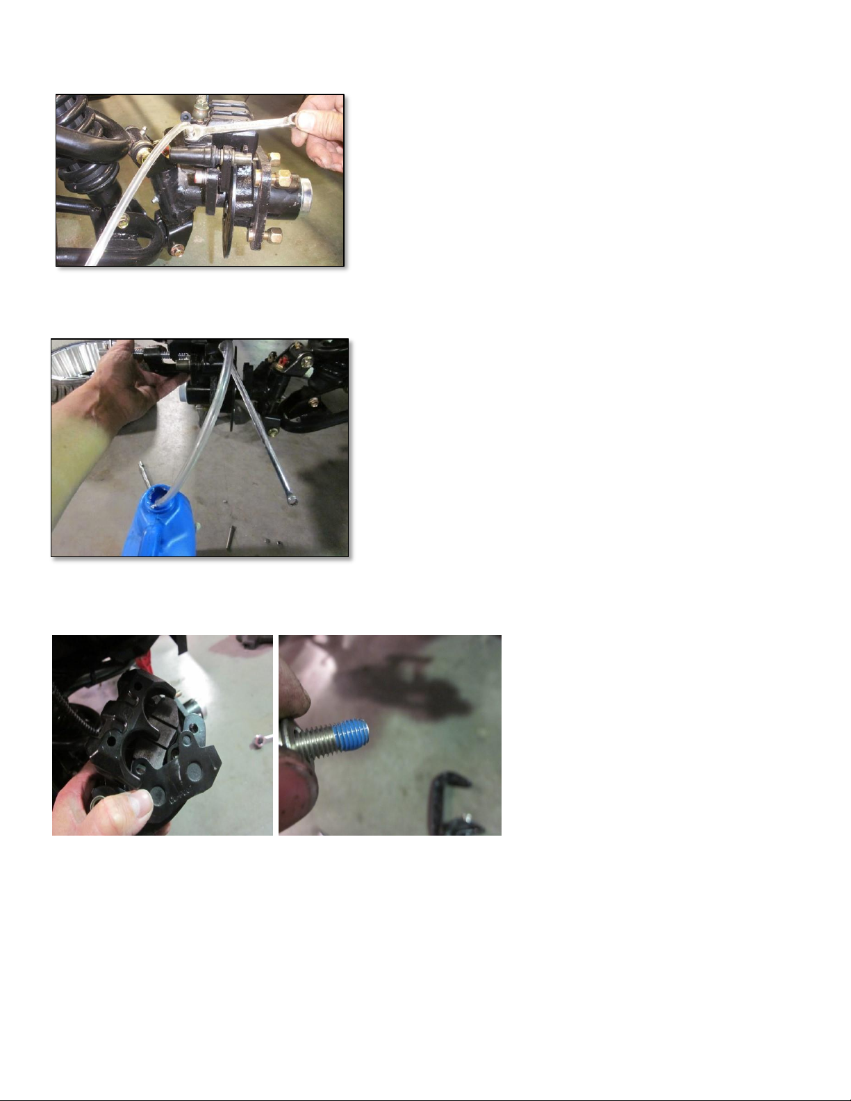
Example: Starting at the right rear wheel (further
from the master cylinder than the left rear wheel),
attach the clear tubing with a catch bottle to the
bleeder screw. An assistant should sit in the driver’s
seat and rapidly pump the brake pedal a minimum of
eight times, then hold down the brake pedal down as far as possible. This is when you open the bleeder screw to release
air, then close it. Instruct the assistant to pump up the brakes again. Repeat this process until clear fluid with no air
bubbles is coming from the brake system. Remember to continually check the reservoir and top off with brake fluid.
When you begin to see what is referred to as froth (a mixture of brake fluid and air) –pressure will begin to rise quickly
with each successive brake pump and release.
The following steps (3-6) will explain and depict what is performed on each wheel.

Page 6
Step 3:
When you manually bleed the brakes (i.e. without a vacuum bleeder) sometimes an air bubble will be trapped in the upper
part of the caliper of the front disk brakes. Follow these steps to remove the air bubble.
1. As you face each disk brake (driver side and passenger side) there are 2 bolts that secure each caliper. Remove the
rear bolt and loosen the front bolt.
2. Tilt the caliper towards the front of the vehicle.
3. Go to step 4 (top of next page).
Note: There are RARE occasions when an air bubble will not escape. If this occurs follow these additional steps.
1. Remove both bolts that secure the caliper.
2. Remove the brake pad retaining bolts.
3. Remove the outside pad and leave the inside pad.
4. Using a C clamp, tighten the C clamp as you push the inside pad inward until the piston is completely compressed.
CAUTION: It is critical to use even pressure. Do not create torque on the piston when tightening the C clamp.
5. After the piston is fully compressed, tilt the caliper towards the front of the vehicle.
6. Go to step 4 (top of next page).

Page 7
Step 4:
Install wrench on bleeder, along with a clear hose, to help recover any
lost fluid. Let the hose empty into a catch container or bottle (see
picture below). This will also help to keep any air from being sucked
back into the caliper or rear cylinders.
Step 5:
With a technician present you can now start the bleeding process.
With technician 1 pumping the pedal for several pump cycles, hold the
pedal while technician 2 opens the bleeder valve. Close the valve and
repeat this step until no air is present in the clear hose. When opening
the bleeder make sure it is held at a horizontal position. This will also
help remove the trapped air. Repeat this process on all wheels.
Step 6:
Once the bleeding procedure is finished, re-
install the brake pads and reassemble the
brake calipers to the mounting brackets.
When installing mounting bolts in caliper
bracket, do so with a small amount of 242
Loctite as shown.
Step 7: Once all steps are completed:
•Reinstall all parts previously removed making sure all fasteners are torqued to specification.
•Pump the brake. The pedal should travel a couple of inches before it has a good firm pressure stop.
•Top off the brake fluid (DOT 3) reservoir to the fill line and install the rubber seal and cap.
•Install the wheels and test drive.

Page 8
Vacuum Brake Bleeder
A vacuum brake bleeder creates suction and eliminates the need for a second
person to pump the brakes. In lieu of “pushing” the fluid thru the system by
building pressure from the brake pedal, vacuum (or negative) pressure pulls the
fluid out the bleeder valve. Vacuum pressure is built up by “pumping” the handle.
When the bleeder valve is opened the vacuum pressure “sucks” the brake fluid out
of the system via the bleeder valve.
Once the components are assembled, connected and sufficient negative pressure
is built up, you simply open the bleeder valve and close the valve before the
negative pressure drops to a predefined amount. It is important to maintain a
negative pressure anytime the bleeder valve is open and never let it to drop to zero.
There are different types of vacuum brake bleeders. The one depicted to the right is an inexpensive hand-held model
(around $30).
Follow all prescribed steps when using a vacuum brake bleeder. The only difference is a person is not required to build
up pressure via the brake pedal.
The link below will show a short video on how to use a hand-held vacuum brake bleeder.
https://www.youtube.com/watch?v=NUhOpYKmnYc
Master Cylinder Adjustment
Adjusting the master cylinder involves increasing or decreasing the amount of distance the internal master cylinder
plunger travels inside the master cylinder. This distance is reflected by the amount of brake pedal travel—from initial
depression to brake engagement. The optimum brake pedal travel distance is 2-inches.
The location of the master cylinder is directly under the brake pedal, and is accessible from under the cart. Access is
facilitated by jacking up the front of the cart and placing on jack stands. It is important to follow all required safety
precautions outlined in the Tomberlin E-MERGE Service Manual on Tomberlin University.

Page 9
Adjustment Steps:
Note: Counterclockwise and clockwise are based upon looking from the rear of
the vehicle toward the front of the vehicle.
1. Loosen the jam nut by turning it counterclockwise (to the left).
2. Turn the push rod with your fingers.
a. Counterclockwise (to the left) will shorten the brake pedal travel.
b. Clockwise (to the right) will lengthen the brake pedal travel.
3. Determine the length of brake pedal travel. See graphic to the right.
4. If there is 2-inches of travel tighten the jam nut. If not, repeat step 2.
Other manuals for E-MERGE
1
Other Tomberlin Automobile Accessories manuals
Popular Automobile Accessories manuals by other brands

Harmar Mobility
Harmar Mobility AL001 Installation and owner's manual

ALCOHOL DETECTION SYSTEMS
ALCOHOL DETECTION SYSTEMS ADS Determinator user manual

Whispbar
Whispbar K593W Fitting instructions

POOL-LINE
POOL-LINE 110234 Assembly instructions

Go Rhino
Go Rhino 565460T installation instructions

Arkon
Arkon CM018-KST-2 installation instructions