Tomey TMS-5 User manual
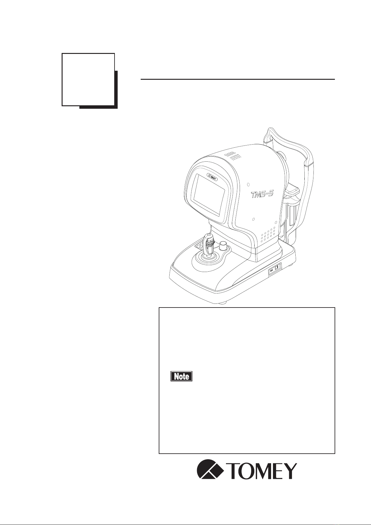
INSTRUCTION MANUAL
Topographic Modeling System
TMS-5
Read this manual thoroughly before using the
instrument to ensure correct and safe operation.
Contact Tomey Corporation or our local distributor
if you have any questions or you encounter any
problems during operation.
■Always follow the operation
procedures described in this manual.
■Keep this manual in a readily accessible
location while operating this instrument.
■Contact our local distributor if you lose
this manual.
229A9090-1D


i-1
i Important safety information
Do not install this instrument in a location where explosives or inflammable
substances are used or stored. Fires or explosion may occur.
Do not remove the cover of the instrument. Otherwise, you may be directly exposed
to high voltage sections.
Do not disassemble or modify the instrument. Otherwise, you may be directly
exposed to high voltage sections.
The personal computer specied in this manual and an Isolation transformer that
isolates the power source for the personal computer from the commercial power
source are required to use this instrument. (No Isolation transformer is required
when using a personal computer specically designed for medical equipment.) Be
sure to observe the following precautions in relation to your personal computer
and Isolation transformer in order to safely use them as part of a medical
equipment system. Refer to “8. Specications” for the performance requirements
of the personal computer and Isolation transformer. Contact our local distributor
or Tomey Corporation if you have any questions.
Use a personal computer conforming to IEC60950-1 and an Isolation transformer
conforming to IEC60601-1. Otherwise, they may not function safely as part of a
medical equipment system.
Connect the power cord of the personal computer to the Isolation transformer, not
directly to a commercial power source. Otherwise, they may not function safely as
part of a medical equipment system.
Disconnect the power cord from all the connected devices before installing and/or
servicing this instrument. Otherwise, you may get an electric shock.
Do not place the Isolation transformer directly on the oor when in use.
Do not connect a plug-in socket or extension cord to the Isolation transformer.
Only use the specied terminal for connection to the main unit of this instrument.
Using any other type of terminal may result in failure of the instrument.
Do not connect electric appliances not provided in the system package to the
Isolation transformer. Otherwise, failure may occur to the Isolation transformer or
electric appliances.

i-2
Do not place water or chemicals on the instrument. Any water or chemicals
entering the instrument may cause an electric shock or failure.
This instrument is a diagnostic/capturing device specifically designed for
ophthalmology. Never use the instrument for other purposes.
When operating this instrument connected to other devices not described in
this document, only use devices that satisfy IEC60601-1 or equivalent safety
requirements or that conform to IEC60950 and whose power source is insulated
with the attached Isolation transformer, in order to satisfy the safety requirements
regarding the medical equipment.
The total rated input of devices to be connected to the Isolation transformer is
less than 500 VA. Use the transformer to supply power only to devices intended
to comprise part of the system.
Do not connect the power source of the personal computer, which is connected
to this instrument for operation, directly to the socket on the wall. Otherwise, an
electric shock or failure may occur.
i-3
!
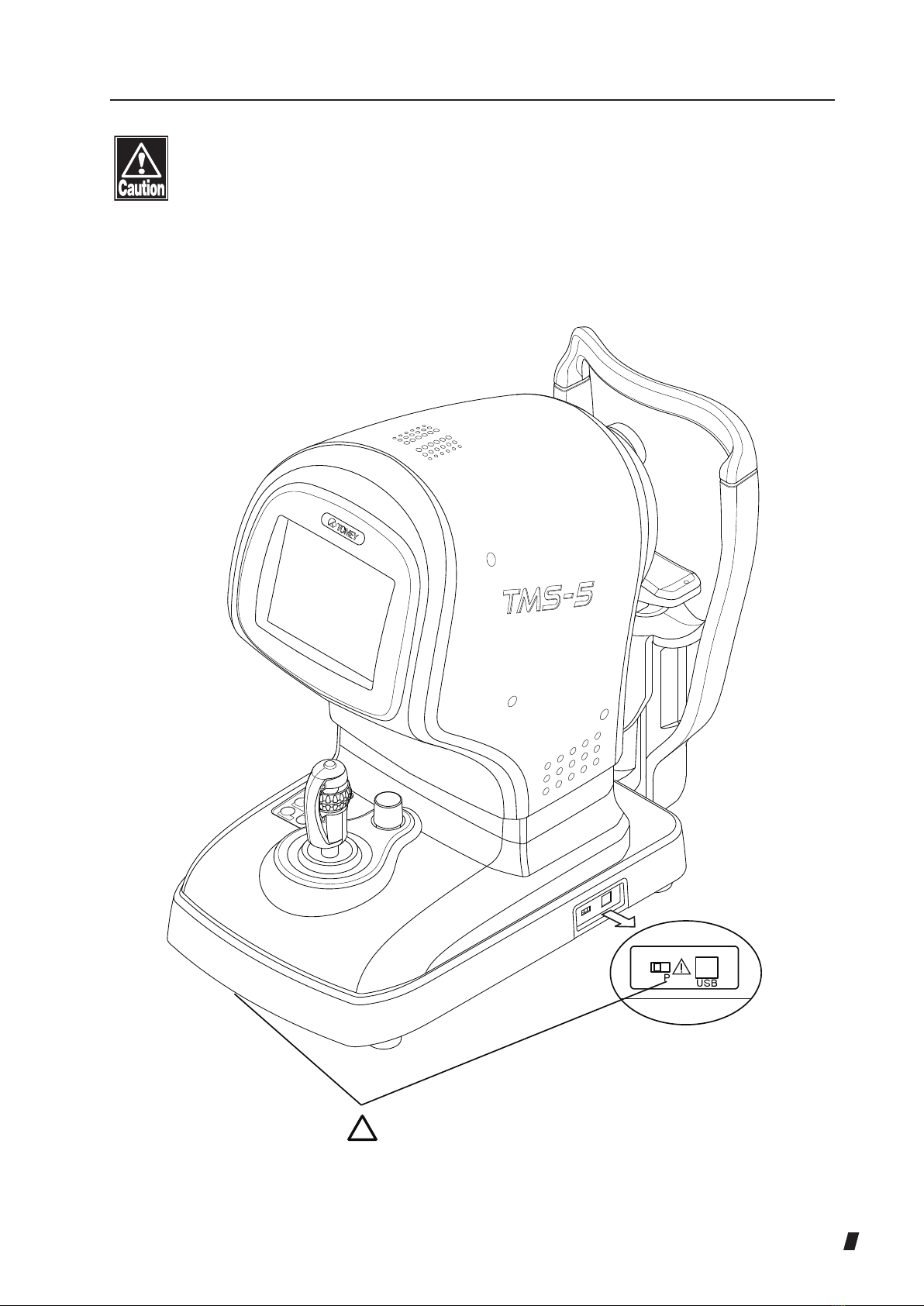
Never mark or damage the caution labels on the instrument. The caution labels
are provided at two locations as shown below.
If a label is damaged or becomes illegible, please contact Tomey Corporation or
our local distributor.
Main unit

i-4
This page is intentionally blank

ii-1
ii How to read this manual
Outline This manual is structured as follows.
1. PRIOR TO USE
Describes safety precautions and important information to
be understood before installing and using the instrument.
2. NAMES AND FUNCTIONS OF PARTS AND
COMPONENTS
Describes names and functions of each section of the
instrument.
3. OPERATION PROCEDURES
Describes information required for installing and using the
instrument.
4. TECHNICAL INFORMATION
Describes useful technical information about the
instrument.
5. INSPECTION AND MAINTENANCE
Describes procedures for replacing consumable parts etc.
that the user of the instrument should normally perform.
6. TROUBLESHOOTING
Describes how to solve problems.
7. Consumables and Options
Describes consumable parts and optional equipment.
8. Specications
Describes the specications of the instrument.
9. Index
Refer to the index when needed.

ii-2
SYMBOLS USED IN THIS MANUAL
Sentences accompanied with the symbols below indicate the
following:
This is a precaution that, if unheeded, will result in a
hazardous situation where there is an imminent danger
of serious injury or death.
This is a precaution that, if unheeded, could result in
a hazardous situation where there is a possibility of
serious injury or death.
This is a precaution that, if unheeded, may result in
a situation where there is a possibility of minor or
moderate injury or damage to property.
This is additional information which may contain
special precautions on company policies related, either
directly or indirectly, to the safety of personnel or to the
protection of property.

iii-1
iii Contents
i Important safety information .....................................................................................i-1
ii How to read this manual ......................................................................................... ii-1
Outline ................................................................................................................ii-1
SYMBOLS USED IN THIS MANUAL..................................................................ii-2
1. PRIOR TO USE.....................................................................................................1-1
1.1 Precautions for operation .............................................................................1-1
1.2 Checking package contents ........................................................................ 1-6
1.3 Glossary.......................................................................................................1-7
1.4 Indication for Use ....................................................................................... 1-11
2. NAMES AND FUNCTIONS OF PARTS AND COMPONENTS.............................2-1
2.1 System .........................................................................................................2-1
2.1.1 Over view ..............................................................................................2-1
2.1.2 Connection diagram .............................................................................2-2
2.2 Front of the instrument (physician's side) .................................................... 2-3
2.3 Rear of the instrument (patient's side)......................................................... 2-5
2.4 Screen of the main unit ............................................................................... 2-6
2.4.1 Ring topo mode screen ....................................................................... 2-6
2.4.2 Slit mode screen.................................................................................. 2-8
2.5 Personal computer screen .........................................................................2-10
2.5.1 Examination List screen .....................................................................2-10
2.5.2 Capture screen...................................................................................2-15
2.5.3 Analysis screen ................................................................................. 2-22
3. OPERATION PROCEDURES .............................................................................. 3-1
3.1 Safety precautions ...................................................................................... 3-1
3.1.1 Precautions for installing the instrument.............................................. 3-1
3.1.2 Precautions for connecting the power cord ......................................... 3-2
3.1.3 Precautions for laser beam.................................................................. 3-3
3.2 Preparation before use................................................................................ 3-4
3.2.1 Considerations for external light interference ...................................... 3-4
3.2.2 System connection .............................................................................. 3-5
3.2.3 Release measurement section stopper ............................................... 3-6
3.3 Preparation for capturing............................................................................. 3-7

iii-2
3.3.1 Turning the power on........................................................................... 3-7
3.3.2 Entering patient information................................................................. 3-9
3.3.3 Selecting the capture mode................................................................3-10
3.4 Capturing ...................................................................................................3 -11
3.4.1 Patient's eye height adjustment ..........................................................3 -11
3.4.2 Using the joystick................................................................................3-12
3.4.3 Capturing in ring topo mode ...............................................................3-13
3.4.4 Capturing in slit mode.........................................................................3-16
3.4.5 Checking captured images.................................................................3-19
3.5 Settings for main unit ................................................................................ 3-21
3.5.1 Initial setup (Setup) ............................................................................ 3-21
3.5.2 Temporary setup (Temporary) ........................................................... 3-24
3.6 Analysis..................................................................................................... 3-26
3.6.1 Basic operation.................................................................................. 3-26
3.6.2 Analysis type ..................................................................................... 3-46
3.6.3 Map scale.......................................................................................... 3-68
3.6.4 Quantitative index ................................................................................ 3-76
3.6.5 Optional function of map.................................................................... 3-80
3.6.6 Other map display modes and applications ......................................... 3-91
3.7 Output of results........................................................................................ 3-97
3.7.1 Printing .............................................................................................. 3-97
3.7.2 Saving les ........................................................................................ 3-98
3.8 Utilities ...................................................................................................... 3-99
3.8.1 Handling of patient ID .......................................................................... 3-99
3.8.2 Data Tables ........................................................................................3-104
3.8.3 Exporting/deleting examination data...................................................3-109
3.8.4 Importing examination data ................................................................ 3 -112
3.8.5 Export patient list................................................................................ 3 -115
3.8.6 TMS Data Import................................................................................ 3 -116
3.9 System Setup........................................................................................... 3 -117
3.10Analyzing in ring topo mode only .............................................................3-124
3.11 Closing the system ...................................................................................3-126
3.12OKULIX....................................................................................................3-127
3.12.1 Precautions when using OKULIX ......................................................3-127
3.12.2 Data output to OKULIX .....................................................................3-128

iii-3
4. TECHNICAL INFORMATION ............................................................................... 4-1
4.1 Corneal refractive index used to calculate refractive power distribution ...... 4-1
4.2 Calculating the keratometer simulation values ............................................ 4-1
4.3 Refractive power correction by analysis of capturing in slit mode ............... 4-2
4.4
Axial direction and symbol of alignment and pupil offset .................................4-2
4.5 Direction of external light interference that affects capturing in slit mode ... 4-3
4.6 Fourier analysis........................................................................................... 4-4
5. INSPECTION AND MAINTENANCE.................................................................... 5-1
5.1 Warranty ..................................................................................................... 5-1
5.2 Operation life............................................................................................... 5-2
5.3 Inspection.................................................................................................... 5-2
5.3.1 Calibration verication (ring topo mode) .............................................. 5-3
5.3.2 Calibration verication (slit mode)........................................................ 5-4
5.4 Routine maintenance .................................................................................. 5-5
5.4.1 Forehead pad and chin rest................................................................. 5-5
5.4.2 Exterior................................................................................................ 5-5
5.5 Replacing consumables .............................................................................. 5-6
5.5.1 Fuses................................................................................................... 5-6
5.5.2 Chin rest paper.................................................................................... 5-6
5.6 Storing......................................................................................................... 5-7
5.7 Disposal ...................................................................................................... 5-8
6. TROUBLESHOOTING ......................................................................................... 6-1
6.1 Troubleshooting........................................................................................... 6-1
6.2 Actions for error messages ......................................................................... 6-4
6.2.1 Message on the main unit ................................................................... 6-4
6.2.2 Message on the personal computer .................................................... 6-6
7. CONSUMABLES...................................................................................................7-1
8. SPECIFICATIONS ................................................................................................ 8-1
8.1 Specications.............................................................................................. 8-1
8.1.1 Main unit.............................................................................................. 8-1
8.1.2 Required specication of the personal computer................................. 8-2
8.1.3 Required specication of the isolation transformer.............................. 8-2
8.2 Noise........................................................................................................... 8-3

iii-4
8.3 Operating environment................................................................................ 8-3
8.4 Classication............................................................................................... 8-3
8.5 Declaration of conformity to EMC ............................................................... 8-4
8.6 Classication by ISO15004-2 Group 2 instrument ...................................... 8-8
9. INDEX .................................................................................................................. 9-1

1-1
1. PRIOR TO USE
Read this manual thoroughly before using the
instrument to ensure proper and safe operation.
Always follow the operation procedures described in
this manual.
Check that there are no devices that generate a strong
magnetic eld near the instrument. A strong magnetic
eld may cause noise and affect operations including
measurement.
1.1 Precautions for operation
Only allow qualied operators to use the instrument.
Precautions when installing the instrument
Install the instrument in a location free of water or chemicals. Any water or
chemicals entering the instrument may cause an electric shock or failure.
Do not install the instrument in a location where chemicals are stored or gases
may occur. Spilt chemicals or vapor may enter the instrument and result in re.
Check the frequency, voltage, and allowable current (or power consumption) of
the power source. Otherwise, re or electric shock may occur.
Connect the power plug to a grounded 3-pin outlet. Otherwise, a short circuit
due to failure of the instrument may result in electric shock.
Do not place any heavy object on the power cord or squash the power cord.
Fire or electric shock may occur.
Fully insert the power plug into the outlet. Faulty contact, allowing any metal to
contact the exposed terminals of the plug, or dust accumulated on the exposed
terminals of the plug may result in re or electric shock.
Conduct grounding work correctly. Otherwise, you may get an electric shock.
If there is any source of noise (devices including a motor, laser surgical
equipment, etc.) near the instrument, place it as far away from the instrument
as possible. Otherwise, the instrument may malfunction.

1-2
Do not use the instrument in a humid location or where temperature and/or
humidity uctuate signicantly. Moisture in the air may form condensation, and
measurement data and/or the optical system may be affected.
Do not connect a device with data transmission specifications that are not
compatible. Fire or electric shock may occur. Contact Tomey Corporation or
our local distributor before using the instrument while connected to another
device.
Do not hold the head, chin rest, forehead pad, or joystick when moving the
instrument. These components are detachable and the instrument may drop,
resulting in injuries.
Install the instrument in a location not subject to direct sunlight, high
temperature and humidity, or air containing dust, salt and/or sulfur. Otherwise,
failure or malfunction may occur.
Install the instrument in a leveled, stable location free of vibration or mechanical
impact. Otherwise, measurement cannot be conducted correctly. The instrument
also may topple over or fall down, resulting in re or a serious accident.
Install the instrument between the patient and physician so that they can face
each other.
Install the instrument in a location with ample clearance from other devices to
allow smooth inspection.
Check the frequency, voltage, and allowable current (or power consumption) of
the power source.
Precautions before using the instrument
Check that the instrument works properly by inspecting switch and button
operations and the display.
Check that all cables are connected correctly.
Since simultaneous use of multiple devices can cause misdiagnosis or result in
a hazardous situation, exercise caution when using this instrument.
Check the sections that the patient will directly touch.
Peel off the top sheet of chin rest paper and clean the forehead pad with a
cloth dampened with alcohol before capturing images.
Check the power source (discharge condition, polarity, etc.).
Check that the instrument is correctly grounded.
Check that the date set on the personal computer conforms to the actual
operation date and time.

1-3
Precautions during operation
Do not place any container with liquid in it on the instrument. Any liquid
entering the instrument may cause electric shock or failure.
Be sure to touch the “New Patient” button to delete the measurement data
for the previous patient before measuring a new patient. If new measurement
is started without deleting the previous data, the measurement data of the
previous patient may be included.
When changing the capture mode of the instrument, pay attention to prevent
any moving parts from hitting the patient’s eye or nose. Also, be sure that the
patient does not place their hands or ngers near any moving section of the
instrument. Doing so may cause injury.
Be extremely careful not to take too long to capture images or repeat
measurement too many times, as this can stress the patient.
Always check that there are no problems with the entire system and patient to
ensure safety.
If a problem with the instrument or the patient occurs, take appropriate action
such as stopping the instrument to ensure the safety of the patient.
Do not use the radius of corneal curvature and corneal thickness directly to
correct the eye refractive power. Other examination methods should also be
used in conjunction with the above.
If the radius of corneal curvature of this instrument is used directly to select
intraocular lenses, the appropriate lenses may not be selected and further
surgery might be required. Other examination methods should also be used in
conjunction with the above.
When a corneal shape map is used for diagnosis, a thorough review is
necessary, such as performing inspections multiple times and performing
other inspections. Note that analysis errors may occur due to light blockage
by eyelashes and eyelids, misalignment of the center due to unstable sight,
conditions of and/or secretions due to corneal disorder, etc.
Note that if diopter is used as the unit for the radius of corneal curvature, the
value may differ depending on the cornea equivalent refractive index. This
instrument uses the value n = 1.3375. If an incorrect value is used to select
intraocular lenses, further surgery might be required.
When capturing images in ring topo mode, check the display on the Mires
plot screen to conrm that the cone with the correct number of rings is used.
If a cone with the incorrect number of rings is used for capturing/analyzing an
image, the corneal shape or curvature cannot be obtained correctly.

1-4
When moving the head and/or chin rest of the instrument, pay attention to the
position of the patient's face, hands, and ngers. The patient may be injured by
any moving sections of the instrument.
Only use the ring cone of this main unit. Otherwise, the correct corneal shape
or curvature cannot be obtained. The number attached to the ring cone must
be identical to the number attached to the inside of the main unit which can be
seen when the ring cone is detached.
Do not look directly at the laser beam when performing alignment in ring topo
mode. Otherwise, the patient may suffer vision damage.
Do not allow any person to place their hands or ngers in the clearance under
the head or the section under the chin rest of this instrument. Their hands or
ngers may be caught and injured.
Be careful not to touch the patient, personal computer, and monitor
simultaneously. Do not allow the patient to touch the connection terminal.
Do not lean on the instrument or press the instrument from the top. The
instrument may topple over, resulting in mechanical failure or injuries.
Peel off the top sheet of chin paper and clean the forehead pad with a clean
cloth before capturing an image of the next patient. Clean the forehead pad
and chin rest with a cloth dampened with alcohol as needed.
If any smoke, offensive odor, or abnormal sound occurs, turn off the instrument
immediately, disconnect the power plug from the outlet, and contact our local
distributor or Tomey Corporation.
Precautions after operation
Do not place any container with liquid in it on the instrument. Any liquid
entering the instrument may cause electric shock or failure.
Do not use organic solvents such as thinner, benzene, or acetone to clean the
instrument. Fire or electric shock may occur. (These solvents may also corrode
the resin or coating on the cover of the instrument.)
Follow the specied procedures to return the operation switch, dial, etc. to their
original positions and turn the instrument off.
Hold the plug when disconnecting the power cord from the outlet to avoid
placing excessive force on the cord. Pulling the cord may damage the inner
core wires, resulting in electric shock or re.
When disconnecting cords, do not apply too much force to them, for example,
do not hold and pull the cord.

1-5
Refer to “5.4 Routine maintenance” and “5.6 Storing” for instructions on the
cleaning and storage of the instrument.
Clean the instrument at the end of operation in preparation for the next use.
Clean and neatly arrange the accessories and cables.
Do not hold the forehead pad of the chin rest or joystick when moving the
instrument. These devices are detachable and the instrument may drop,
resulting in injuries.
If any failure occurs in the instrument, immediately stop operation, indicate
the failure in the instrument, and contact our local distributor for repairs.
Do not modify the instrument. Doing so may cause electric shock or failure of
the instrument. There is a high-voltage section in the instrument. Touching this
section will result in death or serious injuries.
Disconnect the power cord from the outlet when replacing fuses. Otherwise,
you may get an electric shock, resulting in death or serious injuries.
Use the power cord and fuses provided with the instrument or specified by
Tomey to ensure safety. Also, do not use the accessories provided with the
instrument for other equipment.
Conduct regular inspections of the instrument and components.
When the instrument is not used for 1 month or longer, check that the
instrument is operating correctly and safely before starting operation. Refer to
“5.3 Inspection” in this manual for the relevant procedures.

1-6
1.2 Checking package contents
Open the package and check that the required quantity of
the following items is included and they are not damaged.
If any item is missing or damaged, contact our local
distributor as soon as possible.
Keep the box and packing materials for use when
moving or transporting the instrument.
When taking the instrument out of the box, pull the
outer box upward and then remove the packing
materials. Be careful not to lift the main unit up by
directly holding the head, chin rest, forehead pad, or
joystick. The instrument may be damaged.
●Main unit Topographic Modeling System.................1
● Cone (25 rings) (installed in the main unit.).............1
● Cone (31 rings) ........................................................1
●USB cable................................................................ 1
●Power cord ..............................................................1
●Fuse (2 fuses are installed in the main unit.) ...........4
●Chin rest paper ........................................................1
●Chin rest paper pin ..................................................2
●Dust cover................................................................1
● Model eye (for 25 rings topo mode) .........................1
● Model eye (for 31 rings topo mode) ......................... 1
● Model eye (for slit mode) .........................................1
●Hood........................................................................1
● OKULIX USB GUID.................................................1
● TMS-5 INSTRUCTION MANUAL (this manual) ......1
● TB-1000 INSTRUCTION MANUAL ......................... 1
● TB-1000 INSTALLATION CD ..................................1

1-7
1.3 Glossary
[AS] : Auto Shot.
Function to automatically start measurement when the
patient's eyes are within the measuring range.
[MS] : Manual Shot
[AA] :Alignment Assist.
Auxiliary alignment function in vertical direction only. When
the patient’s eye is close to the measuring range, the head
position automatically moves up/down toward the alignment
target.
[D] :Diopter (Unit for expressing the dioptry; inverse of meters)
[Ks] :Direction and value of the meridian with the largest refractive
power are displayed.
(“s” of “Ks” stands for “steep.”)
“Spherical” is displayed when the difference between the
major meridian value and minor meridian value is less than
0.2D.
[Kf] :Direction and value of the meridian that intersects Ks at right
angles are displayed.
(“f” of “Kf” stands for “at.”)
[MinK] :Direction and value of the meridian with the smallest
refractive power are displayed.
[AvgK] : The average refractive power of Ks and Kf is displayed.
[CYL] :Displays the difference between Ks and Kf as the
components of a corneal cylinder in diopter units.
[Pachymetry(Apex)] :Displays the corneal thickness [µm] at the corneal vertex
position.
[Pachymetry(Thinnest)] :Displays the thinnest corneal thickness [µm] and its position
from the corneal vertex using X / Y coordinates [mm].
[Es/Em] :The eccentricity when approximating the corneal shape (Es
in the Ks meridian direction and Em in the MinK meridian
direction) as an ellipse is displayed.

1-8
[Capture mode] :Ring topo mode and slit mode are available in this
instrument.
[RING TOPO mode] :Similar to conventional TMS, a mode to capture images of
the anterior shape of the cornea by projecting ring-shaped
light onto the cornea of the patient’s eye
[Slit mode] :Image of a corneal cross-section captured using the
Scheimpug principle in slit mode
[Mires ring. image] :Corneal image projected by multiple concentric rings of light
in ring topo mode
[Slit image] :Image of a corneal cross-section captured using the
Scheimpug principle in slit mode.
[Analysis screen] :There are two viewers (MERGED TOPO viewer and RING
TOPO viewer) with multiple analysis screens in each viewer.
[MERGED TOPO Viewer] :Displays the analysis screen that uses MERGED TOPO data
such as the MERGED TOPO map.
[RING TOPO Viewer] :Displays the analysis screen that uses RING TOPO data
such as the RING TOPO map.
[MERGED TOPO Map] :The cornea anterior shape map with analysis capability
enhanced by adding information obtained from images
captured in slit mode to the cornea anterior shape map
created from Mire ring images
[RING TOPO Map] :Cornea anterior shape map created from only Mire ring
images for the conventional TMS series, to be distinguished
from [MERGED TOPO Map]
[MERGED TOPO data] :Result of analysis conducted using both Mire ring images
and slit images.
[RING TOPO data] :Result of analysis conducted using only Mire ring images.
[Color map] :Curvature distribution map that shows the corneal shape
with contour lines.
Table of contents
Other Tomey Medical Equipment manuals

Tomey
Tomey TSL-7000Hdigital User manual

Tomey
Tomey Z Series User manual

Tomey
Tomey AL-2000 User manual

Tomey
Tomey SP-100 User manual

Tomey
Tomey OA-2000 User manual

Tomey
Tomey TCP-2000P User manual

Tomey
Tomey SP-100 User manual

Tomey
Tomey AL-100 User manual

Tomey
Tomey TL-100 User manual

Tomey
Tomey TSL-4000Z User manual


Popular Medical Equipment manuals by other brands

Otto Bock
Otto Bock 743L500 3D L.A.S.A.R. Posture Instructions for use

Otto Bock
Otto Bock Dyneva 50R300N Instructions for use

Otto Bock
Otto Bock 3R95 Instructions for use

Nidek Medical
Nidek Medical Magellan Mapper Service manual

Mopedia
Mopedia RS936 instruction manual

Mizuho
Mizuho MOT-VS700 Series Operator's manual


