Tomey TCP-2000 User manual

USER MANUAL
FOR THE
TCP-2000
CHART PANEL
(40-21122-15-107..02EN)
Rev. 002


Operation Manual
3
CONTENTS
1. INTRODUCTION ..............................................................................................5
1.1. Safety precautions........................................................................................6
2. TECHNICAL DATA..........................................................................................8
3. INSTALATION AND USE ................................................................................9
3.1. Package Content ..........................................................................................9
3.2. Installation..................................................................................................10
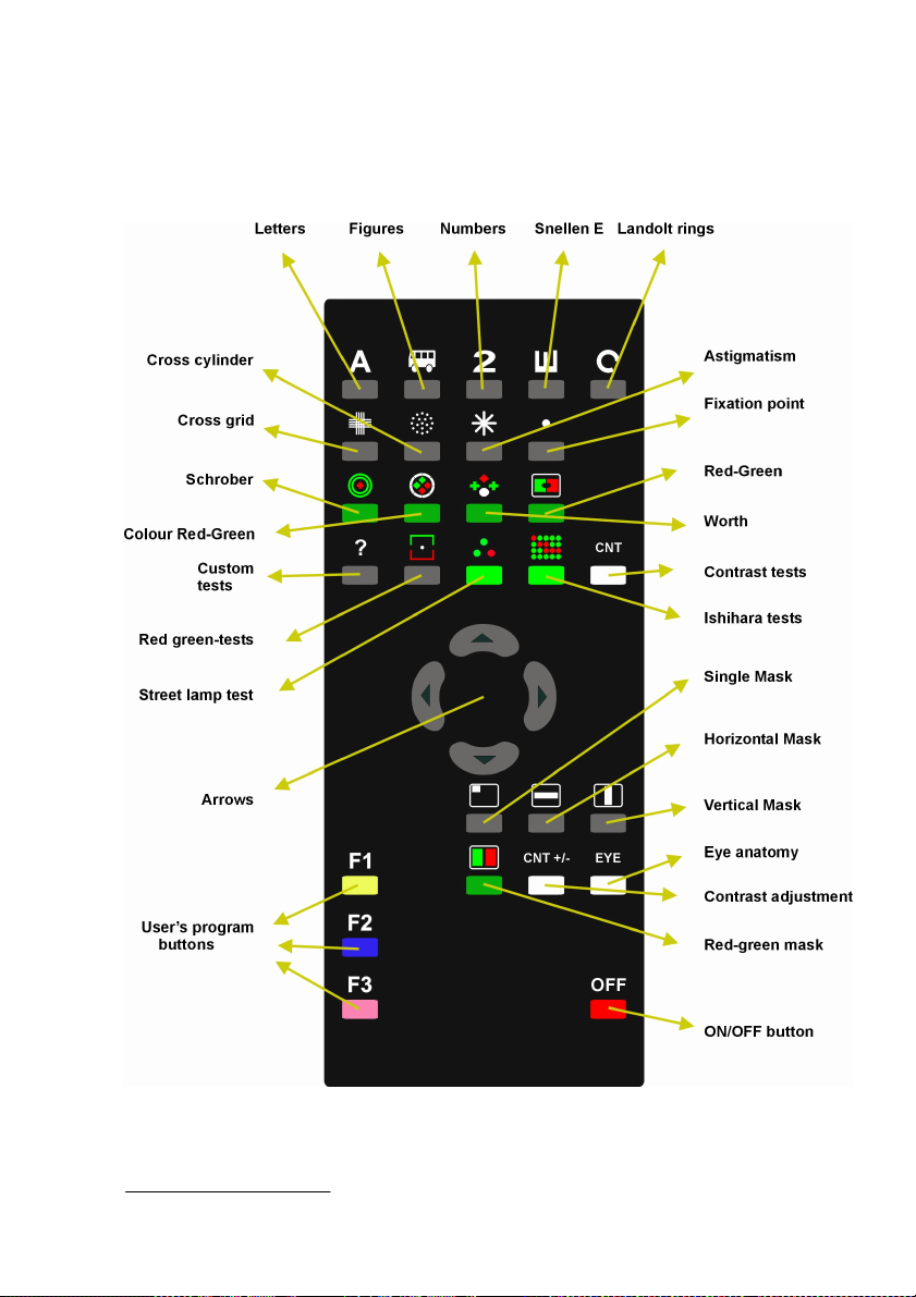
3.3. How to operate chart panel with remote control. ...................................11
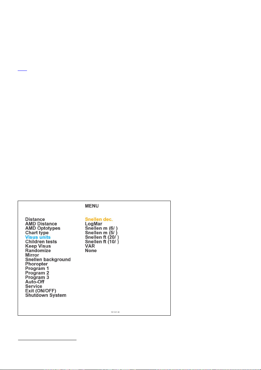
4. CHART PANEL CONFIGURATION............................................................12
Configuration MENU .......................................................................................12
4.1. Distance.......................................................................................................13
4.2. AMD Distance ............................................................................................13
4.3. AMD Optotypes .........................................................................................13
4.4. Chart type – display mode (Snellen, LogMar Modified, Snellen ...........14
Modified, Snellen Contrast chart type)...........................................................14
4.5. Visus units...................................................................................................14
4.6. Children Tests ............................................................................................15
4.7. Keep Visus ..................................................................................................15
4.8. Randomize ..................................................................................................15
4.9. Mirror .........................................................................................................16
4.10. Snellen background .................................................................................16
4.11. Phoropter..................................................................................................17
4.12. User defined programs - PROGRAM 1, PROGRAM 2, ......................18
PROGRAM 3. ...................................................................................................18
4.12.1. Programming Mode ............................................................................18
4.12.2. Executing user’s program ...................................................................18
4.13. Auto-Off....................................................................................................19
4.14. Service mode ( Service )...........................................................................20
4.14.1. Language.............................................................................................21
4.14.2. Distance units: meters, feet ................................................................21
4.14.3. Demonstration mode ( Demo ) ...........................................................21
4.14.4. Colour adjustment...............................................................................21
4.15. Exiting Menu...........................................................................................22
4.16. Shutdown system......................................................................................22
5. TESTS................................................................................................................23
5.1. Standard optotypes ....................................................................................23
5.1.1. Optotype sizes.......................................................................................23
5.2. Chart types .................................................................................................24
5.2.1. Snellen type chart presentation .............................................................24
5.2.2. LogMar Modified type chart presentation ............................................25

Operation Manual
4
5.2.3. Snellen Modified type chart presentation............................................. 26
5.2.4. Snellen Contrast type chart presentation.............................................. 27
5.3. Black-white tests........................................................................................ 27
5.4. Red-green tests .......................................................................................... 28
5.5. Custom tests............................................................................................... 29
5.5.1. Hearing and Speaking Impaired Tests ................................................. 30
5.5.2. Crowding Bars ..................................................................................... 33
5.5.3. Animations........................................................................................... 33
5.5.4. HOTV tests .......................................................................................... 34
5.5.5. 3D Images ............................................................................................ 35
5.5.6. Colour Pictures For Children ............................................................... 35
5.5.7. Amsler tests.......................................................................................... 35
5.5.8. Description of the IR remote functions ................................................ 35
5.6. Vertical Coincidence, Horizontal Coincidence, Minute Stereo............. 35
5.7. Street lamp test.......................................................................................... 36
5.8. Ishihara tests.............................................................................................. 36
5.9. Contrast tests ............................................................................................. 36
5.10. Contrast adjustment ............................................................................... 37
5.11. Eye anatomy pictures.............................................................................. 38
6. MASKS ............................................................................................................. 39
6.1. Single mask ................................................................................................ 39
6.2. Horizontal mask ........................................................................................ 40
6.3. Vertical mask............................................................................................. 41
6.4. Red-green mask......................................................................................... 42
7. SOFTWARE VERSION.................................................................................. 43
8. TROUBLESCHOOTING ............................................................................... 44
9. WARNINGS ..................................................................................................... 45
10. CHART PANEL MAINTENANCE ............................................................. 46
10.1. Cleaning ................................................................................................... 46
10.2. Repairs ..................................................................................................... 47
10.3. Checking .................................................................................................. 47
11. WARRANTY.................................................................................................. 48
APENDIX A ......................................................................................................... 49
COMPONENT LIST ....................................................................................... 49

Operation Manual
5
1. INTRODUCTION
This OPERATION MANUAL describes the purpose, overall view and user
maintenance of the TCP-2000 LCD CHART PANEL. This manual is intended for
medical and technical personnel who will perform tests on patients.
If during operating the Chart Panel you have encountered problems which you can
not solve, or LCD Chart Panel parameters are changed, please, in all these cases
contact the manufacturer.
Only manufacturer’s authorized personnel may carry out the
technical servicing of the Chart Panel!
When during normal operation TCP-2000 device responses to
your remote control command with 1 (beep) signal, it means that
you try to execute not allowed operation!
WARNING !
HINT !

Operation Manual
6
1.1. Safety precautions
Power connections
•Before connecting the power cord to the mains outlet, check that the local
voltage and frequency ratings correspond with the ratings of the Chart Panel.
•Connect panel to a three-wire, grounded receptacle. Do not remove the
grounding prong from the power plug.
•Use intact power cord. Replace the cord if it is cracked, frayed, broken or
otherwise damaged.
•Do not apply tension to the power cord. The cord may get broken.
•Do not use extension cords or adapters of any type.
External connection
•Do not connect any external devices to the Chart Panel other than
specified by the manufacturer.
Explosion Hazard
•Do not use the Chart Panel in the presence of flammable moistures.
Patient Safety
•Do not perform any testing or maintenance of the Chart Panel while it is
being used on a patient.
Cleaning and Service
•Unplug power cord before cleaning or service. Get rid of moisture
completely before reconnecting to the mains outlet.
•Do not use ammonia-, phenol- ,or acetone- based cleaners. These cleaners
may damage the panel surface.
•Do not immerse panel in any liquid. Do not allow liquid to enter the panel
housing.
Installation
•Leave space under and over Chart Panel to allow proper ventilation.
•Do not put any objects on top of the TCP-2000 Chart Panel.
•Do not put Chart Panel in horizontal position because it can not work in
this position.

Operation Manual
7
The manufacturer is responsible for the safety, reliability and performance of the
panel only if:
•Only people authorized by the manufacturer have carried out all the
operations or assembly extensions, adjustments, modifications or repairs.
•The electric plant of the room complies with the electric standards.
•The instrument is utilized in compliance with Operational Manual.
The manufacturer accepts no responsibility for any modifications made to the
Chart Panel outside the factory.

Operation Manual
8
2. TECHNICAL DATA
•Auto off function: adjustable from 4 to 10 minutes
•CP type: TCP-2000
•Power supply: 115 –230 VAC ±10%, 50/60 Hz.
•Power consumption: 19 W max.
•Classification: Class I
•Operating temperature range: +5C to + 40C
•Storage temperature range: 0C to + 40C
•Air pressure: 860 to 1060 hPa.
•Relative humidity: 90% max., without condensation (operation and storage).
•Dimensions: 366 x 291 x 102 mm (L/W/H).
•Weight: 3,5 kg.
•No application part
•IR remote battery type : AA LR6

Operation Manual
9
3. INSTALATION AND USE
3.1. Package Content
•LCD CHART PANEL TCP-2000
•Red-green googles
•Power cord
•Remote control
•Battery AAA 2 pcs.
•Wall mount plate
•Wall mount accessories
•Panel mounting screws
•Operation manual
TEST TYPE TCP-2000
Letters X
Pictures X
Numbers X
Snellen E X
Landolt rings X
Red-green tests X
Astigmatism test X
Fixation Point X
Cross cylinder X
Masks vertical, single, horizontal,
underlining
X
Contrast tests X
Ishihara Tests X
Red-Green Mask X
Street lamp test X
Hands X
Hearing Impaired Mode X
Crowding Bars X
Animations X
HOTV test X
Amsler tests X
Colour Pictures For Children X
3D images X
Anatomy of EYE X
Table 1. TCP-2000 available tests.

Operation Manual
10
3.2. Installation
To assure proper test conditions TCP-2000 Chart Panel should be mounted on the
wall perpendicularly to the patient’s line of sight. The distance from panel to
patient’s eye can be adjusted from 1.9 to 7 meters, depending on test room
conditions. There is possibility to change distance units from meters to feet (6,5 to
23,5 feet). For information on how to adjust the distance please refer to chapter 4.1.
Mounting instruction for TCP-2000 panel is presented below.
1. Each Chart Panel is supplied with wall mounting plate. Use three wall
screws (included in the package) to securely attach mounting plate to the wall.
2. Screw Chart Panel tightly to wall mounting plate using three screws.
Pic. 1. Wall mounting plate.
Chart panel
mounting
threads(side
of the plate).
Wall
mounting
hole.

Operation Manual
11
3.3. How to operate chart panel with remote control.
All functions of Chart Panel are controlled via IR remote control. Picture 2
describes functions of remote control buttons.
Pic. 2. IR remote control.

Operation Manual
12
4. CHART PANEL CONFIGURATION.
If TCP-2000 Chart Panel is securely installed in its operating position, connect the
power cord to the panel first, then the plug power cord to the power outlet. Chart
Panel will start automatically. Flashing LED in the bottom right corner will
indicate start-up process. The panel requires approximately 30 seconds for
initialization. When the LED stops flashing and turns into green and the welcome
screen is displayed, the Chart Panel is ready to use. Install battery into remote
control unit and enter Configuration MENU to set-up Chart Panel options.
Before you start tests on patient you have to configure TCP-2000
properly. To acquire reliable test results it is necessary to set
proper distance between patient and the Chart Panel. Please refer
to chapter 4.1.
Configuration MENU
To enter Configuration MENU press ‘ON/OFF’ button once, TCP-2000 Chart
Panel will switch to stand-by mode. Then press ‘F3’ button, TCP-2000 will display
Configuration MENU. If the Chart Panel is already in stand-by mode, simply press
‘F3’ button.
Following options are available:
Pic.3. Configuration MENU
WARNING !

Operation Manual
13
4.1. Distance
This option allows user to set proper distance between patient and TCP-2000 Chart
Panel. It is crucial that this parameter is correctly set before first use of the Chart
Panel.
1. Enter ‘Distance’, using Arrow Up or Arrow Down button.
2. Press Right Arrow to enable distance edit mode.
3. Use Up and Down Arrow to set required distance.
4. To store value press Left Arrow.
4.2. AMD Distance
This option allows user to set proper distance between patient with AMD
(Age-Related Macular Degeneration) and TCP-2000 Chart Panel.
1. Enter ‘AMD Distance’, using Arrow Up or Arrow Down button.
2. Press Right Arrow to enable distance edit mode.
3. Use Up and Down Arrow to set required distance.
4. To store value press Left Arrow.
It is possible to set the distance from 0,5m – 1,8m.
4.3. AMD Optotypes
Optotypes available in this option are much bigger than standard ones, of visus
units up to ft 20/1600
1. Enter ‘AMD Optotypes’, using Arrow Up or Arrow Down button.
2. Press Right Arrow to enter edit mode.
3. Use Up and Down Arrows to set edited parameter to ‘Yes’ or ‘No’ value.
4. Press Left Arrow to apply changes.
HINT !

Operation Manual
14
4.4. Chart type – display mode (Snellen, LogMar Modified, Snellen
Modified, Snellen Contrast chart type)
Option `Chart type` allows the user to work with Snellen Chart, LogMar Chart
Modified, Snellen Chart Modified or Snellen Contrast (please refer to chapter
5.2.).
1. Enter ‘Chart type’, using Arrow Up or Arrow Down button.
2. Press Right Arrow to enter edit mode.
3. Use Up and Down Arrows to select parameter ‘Snellen Chart’, ‘LogMar
Chart Modified’, ‘Snellen Chart Modified’ or ‘Snellen Contrast’.
4. Press Left Arrow to apply changes.
4.5. Visus units
Option Visus units allows selecting optotype description unit which is displayed
right to the optotype chart.
1. Enter ‘Visus units’, using Arrow Up or Arrow Down button.
2. Press right Arrow, to display list of available units.
3. Press Arrow Up or Arrow Down button to select your favourite chart
description unit.
4. Press Left Arrow to apply changes.
Pic.4. Visus units

Operation Manual
15
Information about currently selected visus scale is continuously
displayed on the left top part of the screen. Set ‘Visus unit’ to
‘None’ to hide this information.
4.6. Children Tests
This option allows to display two kinds of children tests: Standard and Hands.
1. Enter ‘Children Tests’ using Arrow Up or Arrow Down button.
2. Press right Arrow to display list of available tests.
3. Press Arrow Up or Arrow Down button to select your favourite test type.
4. Press Left Arrow to apply changes.
4.7. Keep Visus
When you activate this option, visus values (size) will not change when you switch
to other chart types or tests.
Example:
Activate ‘Keep Visus’ option.
Press button ‘A’ to select the biggest Letter chart.
Press two times ‘↓’ to display smaller size of Letters charts.
Press ‘2’ to select Number chart. Optotype size will not be changed to
the biggest one but will stay at the same size level.
1. Enter ‘Keep Visus’, using Arrow Up or Arrow Down button.
2. Press Right Arrow to enter edit mode.
3. Use Up and Down Arrows to set edited parameter to ‘Yes’ or ‘No’ value.
4. Press Left Arrow to apply changes.
4.8. Randomize
If ‘Randomize’ is enabled ( ‘Yes’ option selected ) all optotypes will be displayed
on chart pictures in random manner.
HINT !

Operation Manual
16
1. Enter ‘Randomize’, using Arrow Up or Arrow Down button.
2. Press Right Arrow to enter edit mode.
3. Use Up and Down Arrows to set edited parameter to ‘Yes’ or ‘No’ value.
4. Press Left Arrow to apply changes.
4.9. Mirror
Option `Mirror` allows to display all tests in mirror presentation.
.
1. Enter ‘Mirror’, using Arrow Up or Arrow Down button.
2. Press Right Arrow to enter edit mode.
3. Use Up and Down Arrows to set edited parameter to ‘Yes’ or ‘No’ value.
4. Press Left Arrow to apply changes.
4.10. Snellen background
Option ‘Snellen background’ allows to select black or white background for
stripe with sharpness size.
1. Enter ‘Snellen background’, using Arrow Up or Arrow Down button.
2. Press Right Arrow to enter edit mode.
3. Use Up and Down Arrows to set edited parameter ‘Standard’ (black
stripe) or ‘Modified’ (white stripe).
4. Press Left Arrow to apply changes.
After-mentioned pictures present charts with black and white background.

Operation Manual
17
Pic. 5. Screen with black background
Pic.6. Screen with white background
4.11. Phoropter
Set this option to ‘Yes’ when you use TCP-2000 Chart Panel together with
phoropter. Adjust colours ( see chapter 4.14.4.) to assure interpretability with the
phoropter colour filters.

Operation Manual
18
1. Select ‘Photopter’, using Arrow Up or Arrow Down button.
2. Press Right Arrow to edit mode.
3. Use Up and Down Arrows to set edited parameter to ‘Yes’ or ‘No’ value.
4. Press Left Arrow to apply changes.
4.12. User defined programs - PROGRAM 1, PROGRAM 2,
PROGRAM 3.
TCP-2000 Chart Panel allows the user to define his own programs. Each program
is a sequence of up to 20 steps of charts, tests or eye anatomy pictures available
from the panel. Masks and colour filters can be used in combination with charts.
You can store 3 programs, each 20 steps long.
4.12.1. Programming Mode
To define your own program follow step 1 to 4:
1. Choose program you would like to edit using Arrow Up or Arrow Down.
2. Press Right Arrow to enter Programming Mode.
3. Now you can start building your program sequence. Select test you want
to add to current program (picture, tests or masks). To confirm your selection and
add step to the program press ‘F1’ button. Device will signal with 1 beep signal
each properly added step of the program.
4. Press ‘F2’ after program step has been stored to end programming process
and store selected test into the memory of the chart panel.
Device will signal end of programming sequence with message ’End of program’.
Programming mode will be automatically finished and step sequence stored after
you excide number of 20 steps for the program.
You can enter Menu at any moment and change settings, e.g. children tests, chart
type, etc.
4.12.2. Executing user’s program
To execute user-defined program stored in device memory simply press ‘F1’, ‘F2’
or ‘F3’ button. Chart Panel will automatically display first test chart of the program

Operation Manual
19
you selected. Device will signal with 2 beep signal each time you enter user’s
program.
In the left bottom corner of the screen a letter ‘A’ is displayed to inform that user
program mode is executed.
Use right Arrow to move to the next chart of the program, left Arrow to return to
the previous chart. Each program is executed in loops, meaning that each time you
reach last chart of the program, pressing right Arrow will start sequence from the
first step. Pressing left Arrow when the first chart of the program is displayed will
result in jumping to the last step of the program.
To switch to other program or to restart selected program press respectively ‘F1’,
‘F2’ or ‘F3’ button.
To enter normal operating mode press any other button than ‘F1’, ‘F2’, ‘F3’ or
Left and Right Arrow.
4.13. Auto-Off
This function allows user to preset time after which Chart Panel enters stand-by
mode. You can set this time from 4 to 10 minutes.
1. Enter ‘Auto-Off’ using Arrow Up or Arrow Down button.
2. Press Right Arrow to edit time for automatic power off.
3. Use Up and Down Arrow to set required time.
4. To store selected value press Left Arrow.
15 seconds before automatic turn off TCP-2000 will give user two notification
signals (beeps). If TCP-2000 is in Auto–Off mode, you can always turn it on and
return to lastly displayed chart by pressing ‘ON/OFF’ button.
Power OFF – new power saving feature.
TCP-2000 Chart Panel will turn itself off when not used after preset time. This
time is set in factory to 2 hours. Service personnel can adjust it during installation
to 30min, 1h, 2h, 3h and 4h depending on the customer needs. If TCP-2000 is in
off-mode LED on the front panel is also off.
NOTE !

Operation Manual
20
To restart TCP-2000 simply press any key on the remote control. Time needed for
startup is approximately 30sec.
4.14. Service mode ( Service )
1. Select ‘Service mode’, using Arrow up or Arrow down button.
2. Press right Arrow. ‘Enter password’ message will be displayed.
From the remote control type following sequence:
If the incorrect sequence has been entered ‘Invalid service code. Press any key’
message appears. To repeat password entering operation press any button and
repeat procedure.
Service menu options:
1. Language
2. Distance units: meter, feet
3. Demonstration mode (Demo)
4. Colour adjustment
Pic.7. Service menu options
Table of contents
Other Tomey Medical Equipment manuals

Tomey
Tomey OA-2000 User manual

Tomey
Tomey TCP-2000P User manual

Tomey
Tomey TL-100 User manual

Tomey
Tomey MR-6000 User manual

Tomey
Tomey TSL-4000Z User manual

Tomey
Tomey TSL-7000Hdigital User manual

Tomey
Tomey AL-2000 User manual

Tomey
Tomey TMS-5 User manual

Tomey
Tomey UD-8000 User manual

Tomey
Tomey CASIA2 User manual