Tomey UD-8000 User manual
769A9090-0E
INSTRUCTION MANUAL
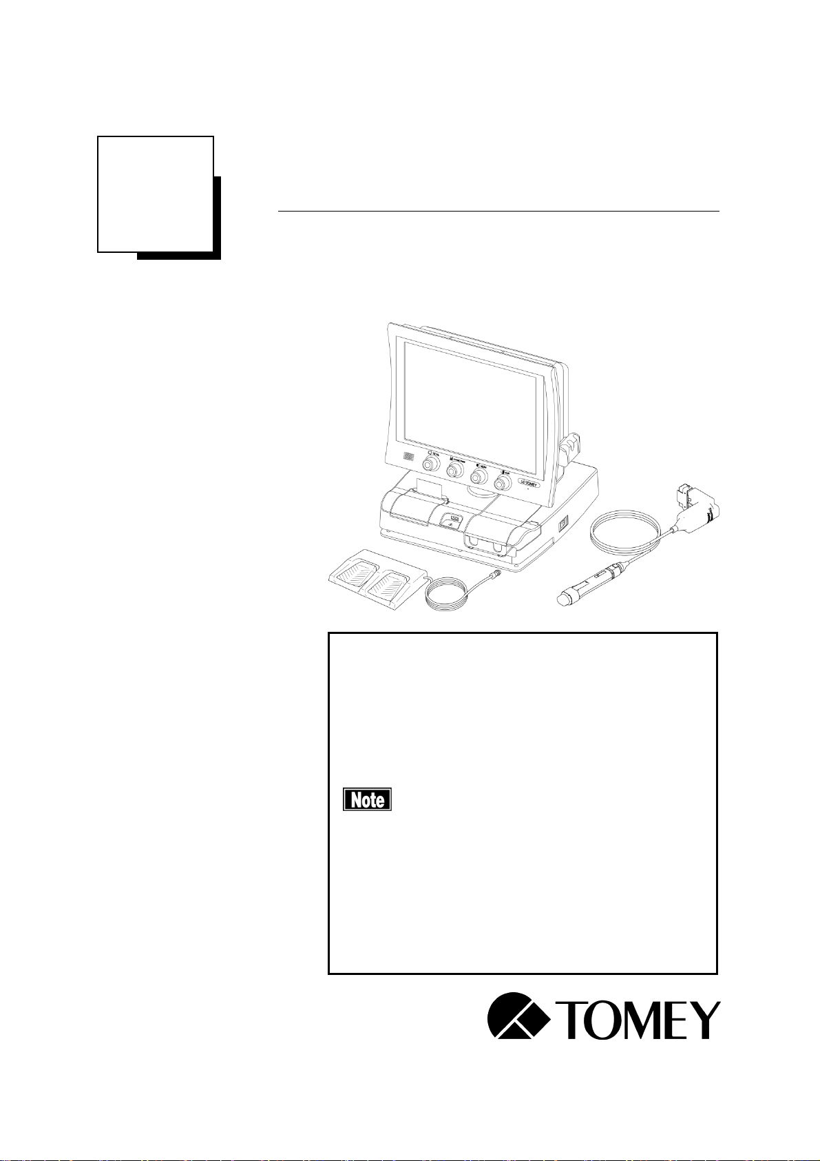
ULTRASONIC B SCANNER
UD-8000
Read this manual thoroughly before using the
instrument to ensure proper and safe operation.
Contact Tomey Corporation or our local distributor if
you have any questions or you encounter any
problems during operation.
■Always follow the operation
procedures described in this manual.
■Keep this manual in a readily
accessible location while operating
this software.
■Contact our local distributor if you
lose this manual.


i-1
■
i Important Safety Information
■
Do not install this instrument in a location where explosives or inflammable
substances are used or stored. Fires or explosion may occur.
■
Do not remove the cover of the instrument. You may be directly exposed to
high voltage sections.
■
Do not disassemble or modify the instrument. You may be directly exposed to
high voltage sections.
■
Disconnect the power cord from all the connected devices before installing
and/or servicing the instrument. Otherwise, you may get an electric shock.
■
Sterilize probes and the eye cup before use.
■
Do not use probes and the eye cup with its contact section damaged.
Measurement error may occur, as well as the cornea or eyelid may be injured.
■
You are cautioned that changes or modifications not expressly approved by
the party responsible for compliance could void your authority to operate the
equipment.
■
Do not place water or chemicals on the instrument. Any water or chemicals
entering the instrument may cause an electric shock or failure.
■
Do not allow water or chemicals to splash on probes, except for the tip caps.
Any water or chemicals entering the instrument may cause an electric shock
or failure.
■
Only use the specified terminal for connection of the instrument. Using
another type of terminal may result in failure of the instrument.
■
This instrument is a diagnostic/measuring device specially designed for
ophthalmology. Never use the instrument for other purposes.
■
The terminal for connecting the instrument to external devices is not isolated
from the internal circuit. Inappropriate wiring may damage the internal circuit.
Never touch any of these terminals and the patient at the same time. Be sure to
contact Tomey or our local distributor before using the external output
terminal.
■
When operating this instrument connected to other devices, only use devices
that satisfy IEC60601-1 or equivalent safety requirements, or that conform to
IEC60950 and whose power source is insulated with an isolation transformer,
in order to satisfy the relevant safety requirements for medical equipment.
■
In-house wireless stations, specified low power wireless stations, and amateur
wireless stations for wireless frequency identification also use the frequency
band used for wireless communication of this instrument. Check that none of

■
i-2
these stations are operating near this instrument before use.
■
When this instrument causes wireless frequency interference harmful to the
in-house wireless station for wireless frequency identification, change the
frequency immediately or take other measures to avoid interference. Stop
emitting wireless waves and contact Tomey or our local distributor.
■
When this instrument causes wireless frequency interference harmful to a
specified low power wireless station or amateur wireless station for wireless
frequency identification, contact Tomey or our local distributor.
i-3
■
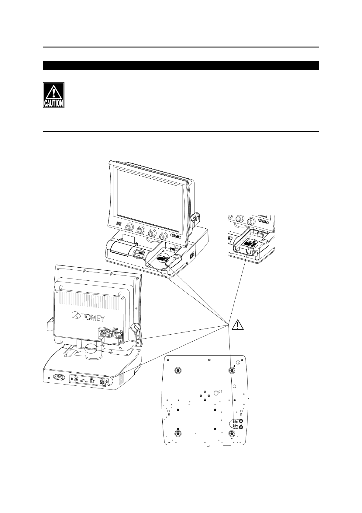
■ Never mark or damage the caution labels on the instrument. The caution
labels are provided at five locations as shown below.
■ If a label is damaged or becomes illegible, please contact Tomey
Corporation or our local distributor.
i-1

■
i-4
■ This device complies with FCC RF radiation exposure limits set forth for an
uncontrolled environment. The antenna used for this transmitter must be
installed to provide a separation distance of at least 20 cm from all persons
and must not be co-located or operating in conjunction with any other
antenna or transmitter.

ii-1
■
ii How to read this manual
Outline
This manual is structured as follows.
1. PRIOR TO USE
Describes safety precautions and important information to be
understood before installing and using the instrument.
2. NAMES AND FUNCTIONS
Describes names and functions of each section of the
instrument.
3. OPERATION PROCEDURES
Describes information required for installing and using the
instrument.
4. TECHNICAL INFORMATION
Describes useful technical information about the instrument.
5. INSPECTION AND MAINTENANCE
Describes procedures for replacing consumable parts, etc.
that the user of the instrument should normally conduct.
6. TROUBLESHOOTING
Describes how to solve problems.
7. CONSUMABLES AND OPTIONAL EQUIPMENT
Describes consumable parts and optional equipment.
8. SPECIFICATIONS
Describes the specifications of the instrument.
9. INDEX
Refer to the index when needed.

■
ii-2
Symbols used in this manual
Sentences accompanied with the symbols below indicate the
following:
■This is a precaution that, if unheeded, will
result in a hazardous situation where there is
imminent danger of serious injury or death.
■This is a precaution that, if unheeded, could
result in a hazardous situation where there is a
possibility of serious injury or death.
■This is a precaution that, if unheeded, may
result in a situation where there is a possibility
of minor or moderate injury or damage to
property.
■This is an additional instruction which may
contain a special precaution on company
policy related, either directly or indirectly, to
the safety of personnel or to the protection of
property.

iii-1
■
iii Contents
i Important Safety Information .............................................................................. i-1
ii How to read this manual.................................................................................... ii-1
Outline................................................................................................................................ ii-1
Symbols used in this manual .............................................................................................ii-2
iii Contents ........................................................................................................... iii-1
1. PRIOR TO USE.................................................................................................1-1
1.1 Precautions for operation.....................................................................................1-1
1.2 Glossary .................................................................................................................1-6
1.3 Checking package contents .................................................................................1-9
1.4 Overview...............................................................................................................1-10
1.4.1 B-mode Image Diagnostic Function.........................................................................1-10
1.4.2 Axial Length Measurement Auxiliary Function .........................................................1-10
1.4.3 Axial Length Measurement Result Display Function (only when connecting
AL-4000/OA-1000) ............................................................................................................1-11
1.4.4 Pachymetry Measurement Result Display Function (only when connecting AL-4000)
1-11
1.4.5 A-scan diagnosis result display (only when AL-4000 is connected).........................1-11
2. NAMES AND FUNCTIONS...............................................................................2-1
2.1 Front of the main unit............................................................................................2-1
2.2 Back of the main unit ............................................................................................2-3
2.3 Screen.....................................................................................................................2-5
2.3.1 Basic structure and common items............................................................................2-5
2.3.2 B-mode image diagnosis ...........................................................................................2-8
2.3.3 Axial length measurement auxiliary function............................................................2-13
2.3.4 Biometry function (available only while AL-4000 is connected) ...............................2-15
2.3.5 Light interference (Opt) function (available only while OA-1000 is connected)........2-19
2.3.6 IOL calculation screen .............................................................................................2-22
2.3.7 Pachymetry function (available only while AL-4000 is connected)...........................2-25
2.3.8 A-scan diagnosis (only when AL-4000 is connected)...............................................2-27
2.4 (Auto power off function.....................................................................................2-30
3. OPERATION PROCEDURES ...........................................................................3-1
3.1 Safety precautions ................................................................................................3-1
3.1.1 Precautions for installing the instrument ....................................................................3-2
3.1.2 Precautions for connecting the power cord................................................................3-3
3.2 Preparation before use..........................................................................................3-4

■
iii-
2
3.2.1 Connections...............................................................................................................3-4
3.2.2 Wireless communication connection with AL-4000 measuring unit .........................3-20
3.2.3 Turning the power on and adjustment after turning the power on............................3-24
3.2.4 Selecting an eye ......................................................................................................3-27
3.2.5 Entering/modifying patient information.....................................................................3-28
3.2.6 All clear of measurement data (preparation for measuring a new patient)...............3-34
3.2.7 Switching modes......................................................................................................3-35
3.3 B-mode image diagnosis ....................................................................................3-38
3.3.1 Selecting a probe.....................................................................................................3-38
3.3.2 Displaying probe angle ............................................................................................3-39
3.3.3 Adjustment by gain setting knobs ............................................................................3-42
3.3.4 Patient preparation ..................................................................................................3-44
3.3.5 Obtaining ultrasound image.....................................................................................3-45
3.3.6 Various functions in FREEZE mode.........................................................................3-48
3.3.7 Various functions in real time mode .......................................................................3-101
3.4 Biometry support function ...............................................................................3-107
3.4.1 Obtaining ultrasound image...................................................................................3-108
3.4.2 Various functions in FREEZE mode....................................................................... 3-111
3.4.3 Various functions in real time mode .......................................................................3-114
3.5 Axial length measurement display function (available only when AL-4000 is
connected)...................................................................................................................3-117
3.5.1 Setting measurement conditions............................................................................3-117
3.5.2 Measurement.........................................................................................................3-121
3.5.3 Checking waveforms after measurement ..............................................................3-125
3.6 Calculation functions in light interference (Opt) mode..................................3-132
3.6.1 Selection of patient ID handling method ................................................................3-132
3.6.2 Capturing measurement data................................................................................3-132
3.6.3 Displaying waveform of arbitrary measurement data.............................................3-133
3.6.4 Selecting specific axial length data to be used in calculating IOL power ...............3-135
3.6.5 Deleting and recovering specified measurement data ...........................................3-136
3.6.6 Caliper function......................................................................................................3-138
3.7 IOL power calculation .......................................................................................3-140
3.7.1 Calculation.............................................................................................................3-141
3.7.2 Entering calculation parameters ............................................................................3-142
3.7.3 Setting IOL power formula .....................................................................................3-148
3.7.4 Entering data after surgery ....................................................................................3-149
3.7.5 R/L alignment display function ...............................................................................3-150

iii-3
■
3.8 Corneal thickness measurement display function (available only when AL-4000
is connected)...............................................................................................................3-151
3.8.1 Setting the data type to be displayed.....................................................................3-151
3.8.2 Setting measurement conditions............................................................................3-151
3.8.3 Measurement.........................................................................................................3-164
3.8.4 Checking the measurement data...........................................................................3-166
3.9 A-scan image diagnosis display (only when AL-4000 is connected) ...........3-169
3.9.1 Switching to the A-scan diagnosis display .............................................................3-169
3.9.2 Setting analysis method.........................................................................................3-170
3.9.3 Measurement.........................................................................................................3-171
3.9.4 Various functions in FREEZE mode.......................................................................3-173
3.9.5 Various functions in real time mode .......................................................................3-176
3.9.6 Analysis function....................................................................................................3-177
3.10 Storing data in USB memory (Axial length measurement display/Corneal
thickness measurement display) ..............................................................................3-181
3.11 Outputting examination data (Axial length measurement display/Corneal
thickness measurement display) ..............................................................................3-182
3.11.1 Printing ..................................................................................................................3-182
3.11.2 The content of printing from built-in printer ............................................................3-183
3.11.3 Transferring measurement data (Axial length measurement display/Corneal thickness
measurement display) .....................................................................................................3-196
3.12 Utilities................................................................................................................3-198
3.12.1 Buttons and icons on the screen............................................................................3-199
3.12.2 Operations for each setting....................................................................................3-209
4. TECHNICAL INFORMATION............................................................................4-1
4.1 IOL power calculation formula .............................................................................4-1
4.1.1 SRK-II formula ...........................................................................................................4-1
4.1.2 SRK/T formula ...........................................................................................................4-3
4.1.3 HOLLADAY formula ...................................................................................................4-5
4.1.4 Hoffer Q formula ........................................................................................................4-7
4.1.5 HAIGIS optimized formula / HAIGIS Standard formula ..............................................4-9
4.1.6 SRK SHOWA formula ..............................................................................................4-11
4.1.7 Double K SRK/T ......................................................................................................4-12
4.2 How to calculate axial length using the biometry function .............................4-14
4.2.1 Phakic eye ...............................................................................................................4-14
4.2.2 Dense cataract eye..................................................................................................4-15
4.2.3 Aphakic eye.............................................................................................................4-15

■
iii-
4
4.2.4 IOL eye ....................................................................................................................4-15
4.3 Amplifier characteristics of the A-scan diagnosis ...........................................4-16
4.4 Checking the software version...........................................................................4-16
4.5 Ultrasound wave output......................................................................................4-16
4.5.1 MI (mechanical index)..............................................................................................4-16
4.5.2 TIS (thermal index of soft tissue) .............................................................................4-16
5. INSPECTION AND MAINTENANCE ................................................................5-1
5.1 Warranty .................................................................................................................5-1
5.2 Operation life .........................................................................................................5-1
5.3 Inspection...............................................................................................................5-2
5.4 Routine maintenance ............................................................................................5-3
5.4.1 Maintenance of measurement probes .......................................................................5-4
5.4.2 Maintenance of main unit...........................................................................................5-7
5.5 Replacing consumables .......................................................................................5-8
5.5.1 Built-in printer paper ..................................................................................................5-8
5.5.2 Fuses.........................................................................................................................5-9
5.6 Storing ..................................................................................................................5-10
5.7 Disposal................................................................................................................5-11
6. TROUBLESHOOTING......................................................................................6-1
7. CONSUMABLES AND OPTIONAL EQUIPMENT ............................................7-1
117H7.1 Spare parts .............................................................................................................7-1
118H7.2 Optional parts ........................................................................................................7-2
119H8. SPECIFICATIONS ............................................................................................8-1
120H8.1 Specifications ........................................................................................................8-1
121H8.1.1 Function specifications (Measurement/Diagnoses/Operation method etc.) ...............8-1
122H8.1.2 Dimensions and weights............................................................................................8-2
123H8.1.3 Display.......................................................................................................................8-2
124H8.1.4 Power source.............................................................................................................8-2
125H8.2 Energy and other consumption ...........................................................................8-3
126H8.2.1 Influences of ultrasound energy on the human body .................................................8-3
127H8.2.2 Ultrasound energy .....................................................................................................8-4
128H8.3 Noise.......................................................................................................................8-8
129H8.4 Operating environment .........................................................................................8-8
130H8.5 Classification .........................................................................................................8-9
131H8.6 Declaration of Conformity to EMC .....................................................................8-10

iii-5
■
9. INDEX ...............................................................................................................9-1

■
iii-
6
This page is intentionally left blank.

1-1
■
1. PRIOR TO USE
■ Read this manual thoroughly before using this
instrument to ensure proper and safe operation.
■ Always follow the operation procedures described in
this manual.
■ Check that there are no devices that generate strong
magnetic field near the instrument. A strong magnetic
field may cause noise and affect measurement.
■ Do not place any other objects on this instrument.
1.1 Precautions for operation
■
Only allow well-trained operators to use the instrument.
■
When using the IOL calculation result to select intraocular lenses,
thoroughly determine the selection by also examining cataract surgery
methods and other inspections.
■
Artifacts may occur in the ultrasonic measurements. If measurement
values are questionable, determine the values by overall judgment (using
the wave forms or results from other equipment).
■
Precautions when installing the instrument and accessories
-Install the instrument in a location free of water or chemicals. Any water or
chemicals entering the instrument or devices may cause an electric shock or
failure.
-Do not install the instrument in a location where chemicals are stored or gases
may occur. Any chemicals or vapor entering the devices may result in fire.
-Check the frequency, voltage, and allowable current (or power consumption)
of the power source. Otherwise, fire or electric shock may occur.
-Connect the power plug to a grounded 3-pin outlet. Otherwise, a short circuit
due to failure of the instrument may result in electric shock.

■
1-2
-Do not place any heavy object on the power cord or squash the power cord.
Fire or electric shock may occur.
-Fully insert the power plug into the outlet. Faulty contact, allowing any metal to
contact the exposed terminal of the plug, or dust accumulated on the exposed
terminal of the plug may result in fire or electric shock.
-Conduct grounding work correctly. Otherwise, you may get an electric shock.
-Do not connect a device with data transmission specifications that are not
compatible. Fire or electric shock may occur. Contact Tomey Corporation or
our local distributor before using the instrument while connected to another
device.
-Install the instrument in a location not subject to direct sunlight, high
temperature and humidity, or air containing dust, salt, and/or sulfur. Otherwise,
failure or malfunction may occur.
-Install the instrument in a leveled stable location free of vibration or
mechanical impact. Otherwise, measurement cannot be conducted correctly.
Also, the instrument may topple over or fall down, resulting in fire or a serious
accident.
-Install the instrument in a location with ample clearance from other devices to
allow smooth inspection.
-Check the frequency, voltage, and allowable current (or power consumption)
of the power source.
-Check the power source (discharge condition, polarity, etc.).
-When the result of the axial length measurement unit is not stable, please use
the axial length value, anterior chamber depth, and crystal lens value which
are displayed in the axial length auxiliary measurement function only as
supplementary information to select adopted values, and do not use them for
IOL calculation or similar.
■
Precautions before operation
-Check the electrical contact of switches, polarity, dial setting, and meters, and
that the instrument is working correctly.
-Check that all cables are connected correctly.

1-3
■
-When you use an arm, please verify that screws are firmly fastened before use.
The probe attached to the arm may be fallen and damaged, or fallen to a
patient's eyeball or eyelid and injury them.
If you move an arm by holding it directly, you may be injured with hands or
fingers caught
.
-Do not allow water or chemicals to splash on probes, except for the tip caps
and the purified water inlet
.
Any water or chemicals entering the instrument
may cause an electric shock or failure.
-Do not allow the patient to touch the terminals for connecting the instrument to
external devices.
-Since simultaneous use of multiple devices can cause misdiagnosis or result
in a hazardous situation, exercise caution when using this instrument.
-Check the sections that the patient will directly touch.
-Check that the instrument is correctly grounded.
-Check that the date set in the instrument conforms to the actual operation date
and time.
■
Precautions during operation
-Do not place any container with liquid in it on the instrument. Any liquid
entering the instrument may cause electric shock or failure.
-Do not allow the patient to touch the terminals for connecting the instrument to
external devices.
-Be sure to touch the “New” button on the main unit to delete the measurement
data for the previous patient before measuring a new patient. If new
measurement is started without deleting the previous data, the measurement
data for the previous patient may be included.
-Do not lean on the instrument or press the instrument from the top. The
instrument may topple over, resulting in mechanical failure or injuries.
-Do not allow water or chemicals to splash on probes, except for the tip caps
and the purified water inlet
.
Any water or chemicals entering the instrument
may cause an electric shock or failure.

■
1-4
-Be extremely careful not to take too much time or too many measurements, as
this can stress the patient.
-Constantly observe that both the instrument and patient are free of problems.
-If a problem with the instrument or the patient occurs, take appropriate action,
such as stopping the device, to ensure the patient’s safety.
-Do not allow the patient to touch the instrument.
-If any smoke, offensive odor, or abnormal sound occurs, turn off the
instrument immediately, disconnect the power plug from the outlet, and contact
our local distributor or Tomey Corporation.
■
Precautions after operation
-Do not place any container with liquid in it on the instrument. Any liquid
entering the instrument may cause electric shock or failure.
-Do not use organic solvents such as thinner, benzene, or acetone to clean the
instrument. Fire or electric shock may occur. (These solvents may also
corrode the resin or coating on the cover of the instrument.)
-Do not allow water or chemicals to splash on probes, except for the tips. Any
water or chemicals entering the instrument may cause an electric shock or
failure.
-Follow the specified procedures to return the operation switch, dial, etc. to
their original positions and turn the instrument off.
-Hold the plug when disconnecting the power plug from the outlet to avoid
placing excessive force on the cord. Pulling the cord may damage the inner
core wires, resulting in electric shock or fire.
-When disconnecting cords, do not apply too much force to them, for example,
do not hold and pull the cord.
-Refer to “5.6 Storing” for instructions on the storage of the instrument.
-Clean the instrument at the end of operation in preparation for the next use.
-Clean and neatly arrange the accessories and cables.

1-5
■
■
If any failure occurs in the instrument, immediately stop operation,
indicate the failure in the instrument, and contact our local distributor for
repairs.
-Do not modify the instrument. Doing so may cause electric shock or failure of
the instrument. There is a high-voltage section in the instrument. Touching this
section will result in death or serious injuries.
-Disconnect the power cord from the outlet when replacing fuses. Otherwise,
you may get an electric shock, resulting in death or serious injuries.
-Use the power cord and fuses provided with the instrument or specified by
Tomey to ensure safety. Also, do not use the accessories provided with the
instrument for other equipment.
-Conduct regular inspections of the instrument and components.
-When any instrument failure occurs, indicate the failure, and contact our local
distributor to request inspection and repair. Do not attempt to repair the
instrument yourself.
-When the instrument is not used for 1 month or longer, check that the
instrument is operating correctly and safely before starting operation. Refer to
“5.3 Inspection” in this manual for the relevant procedures.

■
1-6
1.2 Glossary
[ACD] :Anterior chamber depth measurement
[Acrylic] :Acrylic lens
[Aphakic] :Aphakic eye
[AVG] :Average value
[Axial] :Axial length measurement (biometry)
[A-Diag] :A-mode diagnosis
[B-Axial] :Axial length measurement auxiliary function
[B-Diag] :B-mode image diagnosis
[BD address] :Bluetooth ® Device Address
Number set to each device to identify the connection
[Bluetooth ®] :Bluetooth is a registered mark of Bluetooth SIG, Inc.
[Calibration] :Calibration of B-mode probes, UBM probes, and
pachymetry probes.
[CCT] :Corneal center thickness
[Contact] :Method of taking measurements by directly applying the
contact section of the biometry probe to the center of the
cornea
[Clinical History Method] :Method of calculating the corneal refractive power before
the refractive correction surgery.This is used together
with Double K Method.
[D] :Diopter The unit of refractive power representing the level
of myopia, hyperopia, or astigmatism. Reciprocal of the
focal length measured in meters.
[DATA Transfer] :System to output the examination data created by TOMEY
products as a file
[Export] :To send measurement data to DATA Transfer or Tomey
Link.
[FREEZE] :Status where ultrasound waves are not transmitted
Table of contents
Other Tomey Medical Equipment manuals


