Tool it APOLLO 5-9/9-13 G User manual

FR 02-04 / 23-26
EN 05-07 / 23-26
DE 08-10/ 23-26
ES 11-13 / 23-26
RU 14-16 / 23-26
V1 - 02/10/18 - Ref. 037809
NL 17-19 / 23-26
IT 20-22 / 23-26

2
Le masque APOLLO est conforme à la directive 89/686 CEE relative aux équipements de protection individuelle. Cette conformité est établie par le respect des normes EN
175, EN 166, EN 168 et EN 379.
Organismes notiés
Cellule : Cagoule / Ecran de garde :
Ce manuel est destiné à vous aider dans l’utilisation du masque APOLLO, livré prêt à l’emploi. Pour votre protection, lisez attentivement ces instructions avant l’utilisation et
informez-vous convenablement auprès de votre responsable de sécurité.
AVANT UTILISATION
- Vérier le bon état général du masque
- Les réglages du serre-tête.
- Vérier le bon positionnement et l’état des écrans de garde et du ltre. En cas d’anomalie, veuiller procéder à sa remise en état.
- Vérier que les 4 détecteurs (8) et la cellule ne soient pas obstrués par des poussières ou des débris.
- Vérier que les lms protecteurs sont retirés sur les écrans de garde extérieur et intérieur.
- Vérier que le voyant rouge (5) est éteint sinon procéder au changement des batteries (10).
- Vériez si le niveau de protection correspond aux procédés de soudage employés. Pour vous aider dans votre choix, référez vous au tableau «Procédés de soudage».
FONCTIONNEMENT
Le masque opto-électronique APOLLO commute instantanément de l’état clair à l’état foncé à l’amorçage de l’arc, et retourne à l’état clair lorsque l’arc s’arrête.
1 2 3 4
6
9
7
5
8
10
1. Potentiomètre «soudage-Grind»
2. Potentiomètre «Delay»
3. Potentiomètre «sensitivity»
4. Commutateur de teinte 5-9/9-13
5. Voyant alarme pile déchargée
6. Écran de protection
7. Celulle solaire
8. Détecteurs
9. Filtre
10. Pile lithium (CR2450)
• Potentiomètre interne soudage/Grind :
- Position soudage :
La teinte foncée peut être réglée de 5/9 - 9/13 grâce au bouton extérieur.
• Potentiomètre interne « Sensitivity » : Réglage de sensibilité en fonction de :
- La lumière ambiante: Hors soudage, tourner le bouton vers la position la + sensible (max), puis revenir progressivement vers « min » jusqu’à ce que la
cellule passe au clair.
- Du procédé de soudage : Position « max » pour le soudage TIG basse intensité / Position médiane pour la plupart des procédés de soudage.
• Potentiomètre interne « Delay » : Temps de retour à l’état clair.
Permet de retarder le temps de retour à l’état clair pour se protéger des rayonnements en n de soudure.
Le commutateur interne permet de choisir la plage de réglage soit sur 5-9 ou 9-13.
PRÉCAUTIONS
• Le masque est utilisable pour tous les types de procédés de soudage excepté le soudage Oxyacétylène, le soudage laser et au gaz.
• Un écran de garde extérieur et intérieur doivent être placés systématiquement de part et d’autre du ltre. L’absence d’écran peut provoquer des dommages irréversibles et
un danger pour votre sécurité.
Teinte claire 4
Teinte foncée 5-9/9-13
Dimension du ltre 114x133 mm
Temps de réaction 0,0002 s
Alimentation Solaire + piles
Poids 510 gr
Champs de vision 100x67 mm
Champs d’application MMA 5>400A / TIG 2>300A / MIG-MAG 5>400A / Grind
Garantie 2 ans
Température d’utilisation -5°C / + 55°C
Température de stockage -20°C / + 70°C
RÉGLAGE SERRE-TÊTE
Le masque APOLLO est équipé d’un serre-tête qui offre 4 réglages au soudeur : largeur, hauteur (1), inclinaison (2) et ajustement longitudinal (3).
FR

3
1
32
ENTRETIEN / MAINTENANCE
• Date / Délai de péremption : Pas de date de péremption pour ce produit mais avant chaque utilisation l’état de votre masque APOLLO doit être vérié.
• Le masque APOLLO ne doit pas chuter au sol.
• Ne pas placer d’objets lourds ou d’outils sur ou dans le masque an de ne pas endommager le ltre ou les écrans de garde.
• La détérioration du ltre optoélectronique ou de son écran de garde réduit la vision et le niveau de protection. Remplacez immédiatement les éléments détériorés.
• N’utilisez aucun outil pour enlever des éléments du masque ou du ltre, ceci pouvant entraîner des dommages pouvant provoquer des blessures ou annuler la garantie.
• Nettoyer le ltre Opto-électronique avec un coton propre ou un chiffon spécial pour objectifs.
• Nettoyer et changer régulièrement les écrans de garde.
• Nettoyer l’intérieur et l’extérieur du masque avec un détergent-désinfectant neutre.
• N’utilisez pas de solvant.
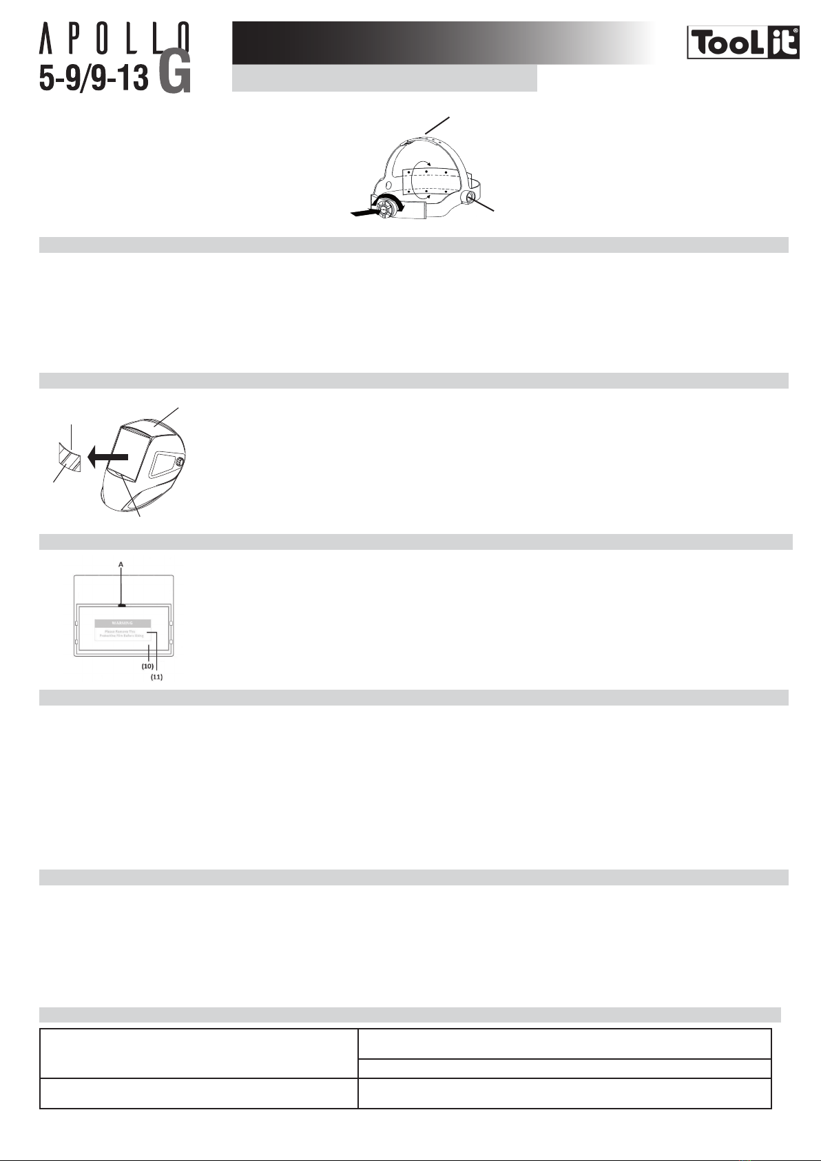
REMPLACEMENT DE L’ ÉCRAN DE GARDE EXTÉRIEUR
2
3
A
1
L’écran de garde extérieur (2) est extractible en plaçant un doigt
sous l’écran sur le point (A) du masque (1).
Lors du changement d’écran, penser à retirer , au préalable, le lm
protecteur (3). Ce lm ne peut être enlevé quand l’écran de garde
est déjà en position dans le masque.
REMPLACEMENT DE L’ ÉCRAN DE GARDE INTÉRIEUR (10)
Pour changer l’écran de garde intérieur (10) , faîtes le glisser, vers le
bas, en placant le doigt sur le point (A.)
Lors du changement, penser à retirer , au préalable, le lm
protecteur (11)
REMPLACEMENT DES PILES
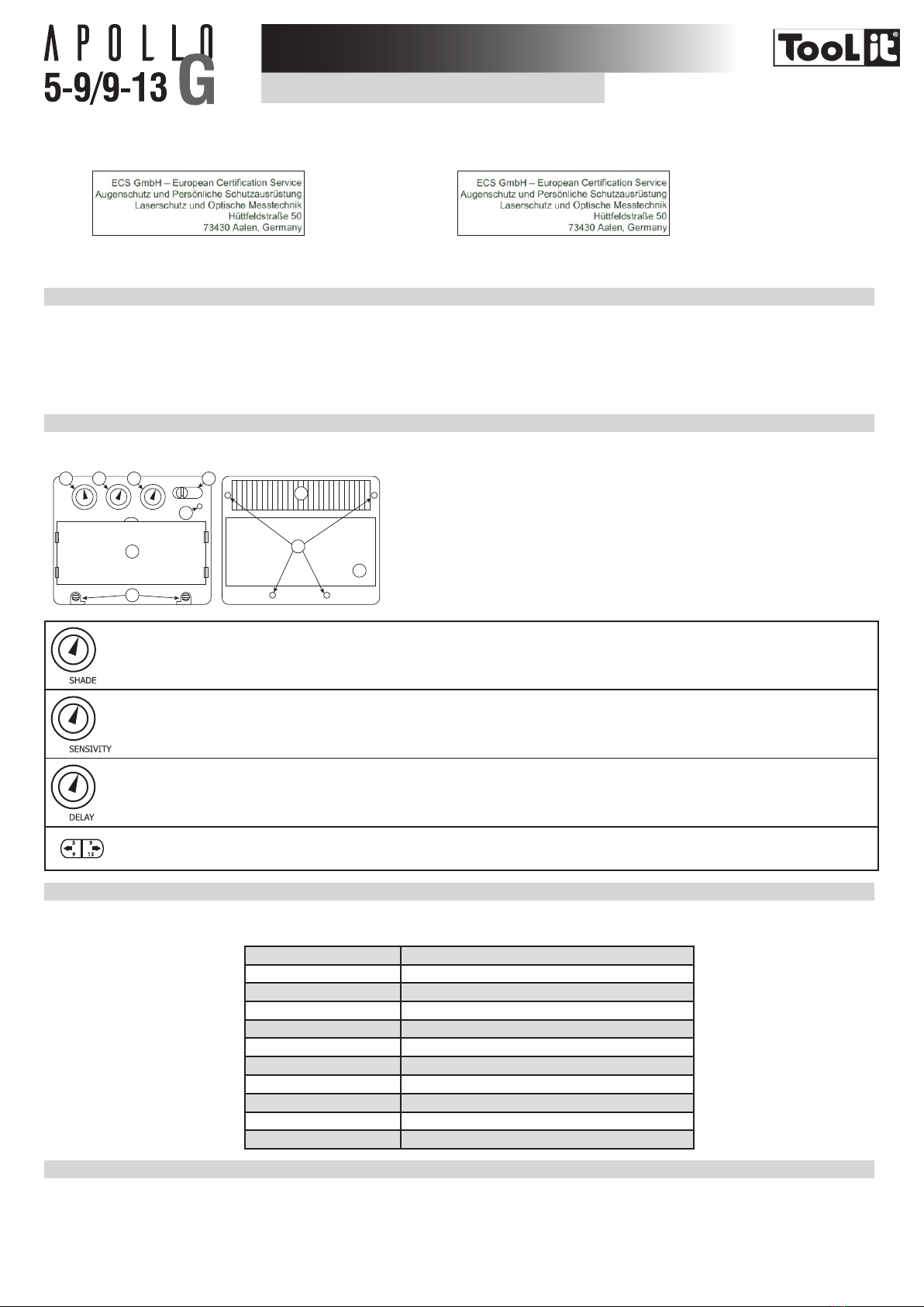
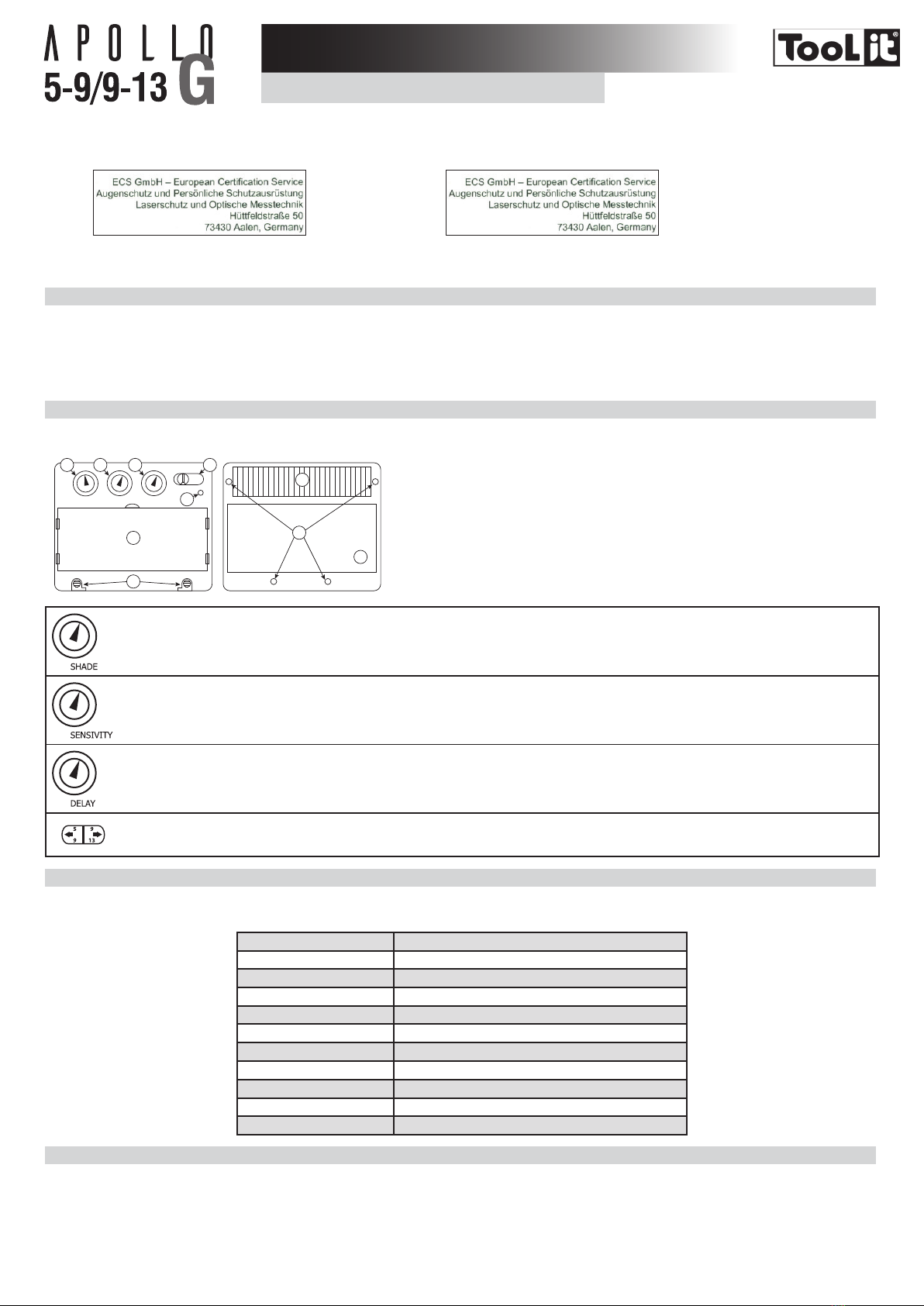
Le ltre opto-électronique utilise 2 piles de 3V au lithium (CR2450). Lorsque le voyant rouge «Alarme faible charge» (5) s’allume, vous devez procéder au changement des 2 piles.
Suivre les instructions ci-dessous pour le changement de piles :
- Retirer la cellule du masque.
- Tirer sur les cache-pile situés en bas de la cellule.
- Replacer la nouvelle pile dans son logement . La polarité « +» doit rester visible.
- Replacer le cache-pile.
- Procéder à la même opération pour la seconde pile.
- Une fois les piles remplacées, le voyant «Alarme faible charge» (5) doit rester éteint.
- Il est conseillé de remplacer les deux piles, une fois par an.
AVERTISSEMENT :
- Recycler les piles lithium usagées. Les piles sont considérées en Europe comme déchets dangereux.
- Ne pas jeter dans la poubelle, à déposer uniquement dans les bacs de collecte pour piles usagées.
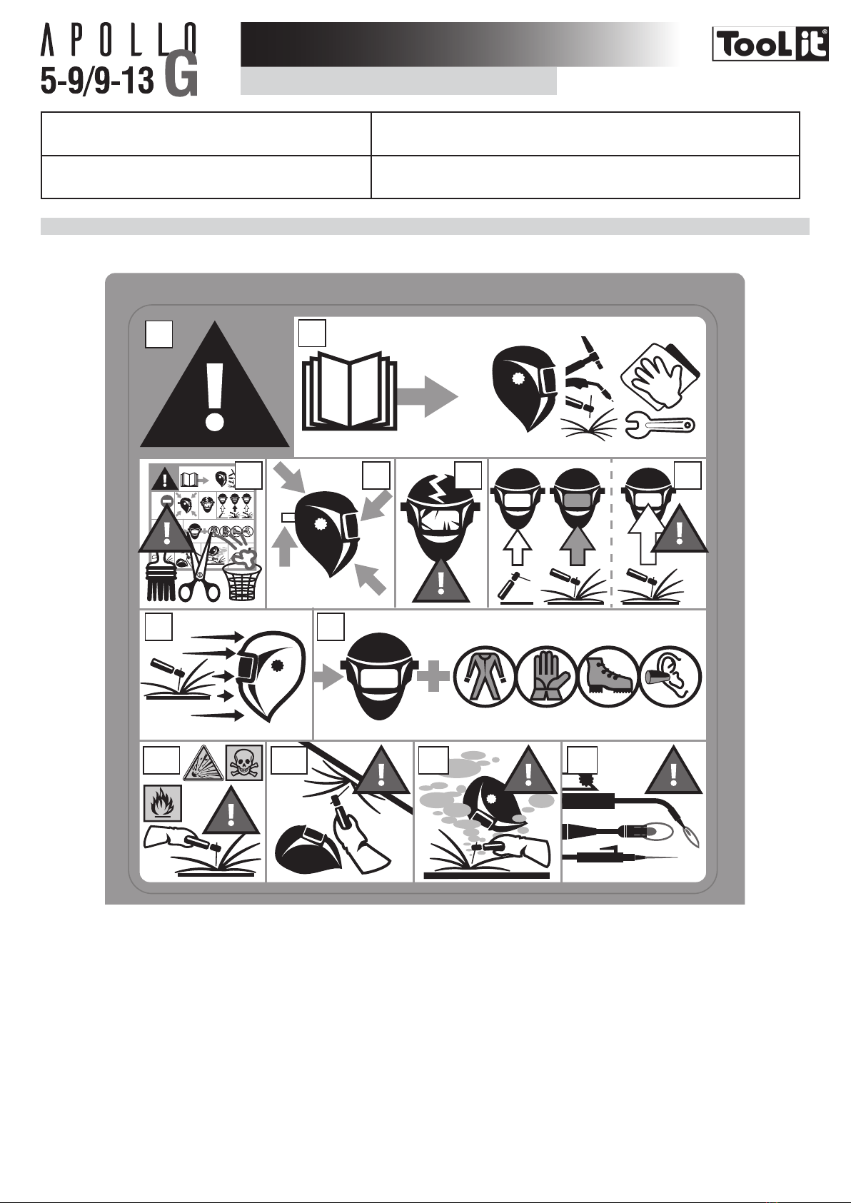
ATTENTION
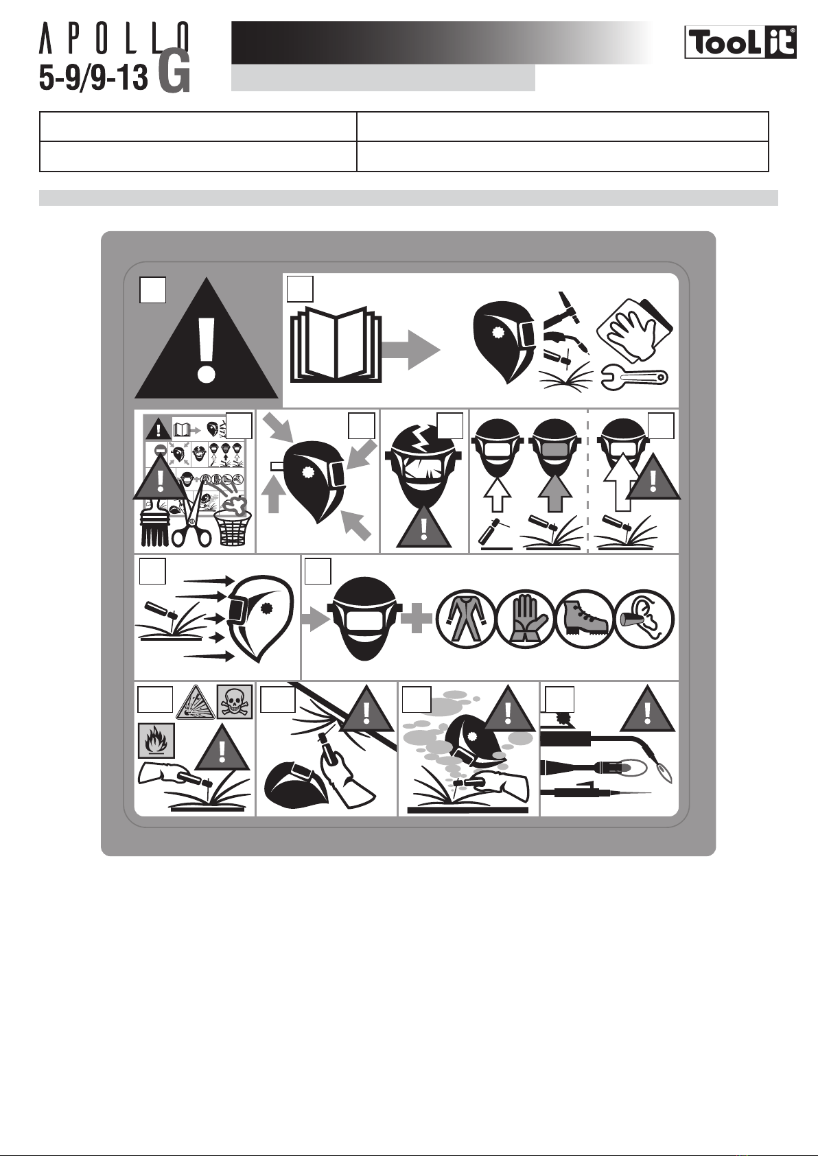
• Cet équipement est destiné uniquement à la protection des yeux contre les rayonnements ultraviolet et infrarouge, les projections incandescentes et étincelles provoquées lors
des opérations de soudage et coupage.
• Le masque apollo n’est pas conçu pour vous protéger contre des chocs importants ou des impacts tels que, des fragments de disques abrasifs ou de disques de meulage, pierres
et autres outils de meulage, mécanismes explosifs ou liquides corrosifs … (liste non exhaustive). Une protection appropriée doit être utilisée lorsque ces dangers existent.
• Le bandeau du serre-tête peut éventuellement engendrer des allergies chez les personnes sensibles.
• Le ltre opto-électronique du masque apollo n’est pas étanche et ne fonctionnera pas correctement s’il a été en contact avec de l’eau.
• Les températures d’utilisation du ltre opto-électronique sont de -5°c à +55°c.
• Les températures de stockage du masque apollo sont de -20°c à +70°c.
ANOMALIES ET REMÈDES
Le Filtre optoélectronique ne fonctionne pas.
Activer la charge solaire en exposant la cellule à la lumière pendant 20 à 30 minutes – vérier
et changer les piles si nécessaire. (alarme faible charge)
Vérier que le potentiomètre est bien sur la position « soudage » (5-9 / 9/13)
Le ltre optoélectronique reste en teinte foncée quand il n’y a pas d’arc
ou quand l’arc est éteint
Vérier les détecteurs et nettoyer si nécessaire.
Ajuster la sensibilité en position basse. Si l’endroit de soudure est extrêmement lumineux, il
est recommandé de réduire le niveau de luminosité.
FR

4
FR
Commutation incontrôlée et scintillement:
Le ltre bascule en teinte claire et foncée pendant la phase de soudage Vérier que les détecteurs soient bien dans l’axe de l’arc électrique, sans obstacle. Tourner le
réglage de sensibilité vers max.
Les cotés sont plus clairs que la zone centrale du ltre optoélectronique C’est une caractéristique naturelle des LCD, ce symptôme n’est pas dangereux pour les yeux.
Cependant pour un confort maximum, essayer de garder un angle de vue proche des 90°
ÉTIQUETTE DE SÉCURITÉ
Cette étiquette est afchée à l’intérieur du masque de soudage. Il est important que l’utilisateur comprenne la signication des symboles de sécurité. Les numéros de la
liste correspondent aux numéros des images.
?
1
A
2
66.1
6.2 6.3 78
345
Légende :
A. Attention! Prendre garde! Il existe des dangers possibles, comme indiqué par les différents symboles.
1. Lire attentivement les instructions avant d’utiliser le matériel ou de souder.
2. Ne pas retirer l’étiquette de prévention et ne pas peindre sur cette étiquette.
3. Respecter les consignes de réglages et d’entretien du ltre, des écrans de garde, du serre-tête et de la cagoule.
4. Inspectez soigneusement le masque et son ltre UV/IR. Remplacer immédiatement les pièces usées ou endommagées. Fissurés, rayés, les verres ltrants ou les écrans de
garde réduisent sérieusement la protection. Remplacer les immédiatement pour éviter d’endommager vos yeux.
5. Attention, si le ltre UV/ IR ne se teinte pas en soudage ou en découpage, arrêter immédiatement. (Consulter la notice d’instructions)
6. Le rayonnement de l’arc peut provoquer des brûlures aux yeux et sur la peau.
6.1. Utiliser un masque de soudage avec une ltration ou une opacité correcte. Porter des vêtements de protection complets.
6.2. Le masque, le ltre et les écrans de garde ne garantissent pas une protection illimitée contre des chocs ou des impacts importants, des mécanismes explosifs ou
liquides corrosifs. Eviter le soudage ou le découpage dans ces environnements sévères.
6.3. Ne pas souder ou découper au dessus de votre tête avec ce masque.
7. Eloignez votre tête de la zone enfumée. Utilisez une ventilation forcée ou un système local d’aspiration pour éliminer les fumées.
8. Le soudage-découpage oxyacétylène, au laser ou au gaz n’est pas autorisé avec ce masque.

5
The welding helmet APOLLO complies with EEC directives 89/686 CEE. This conrmity is established in compliance with EN 175, EN 166, EN 168 and EN 379.
Notied bodies / organisations :
Cell : Welding hood / Protection
screen :
This manual has been made to help you using this helmet, ready to use. For your protection, please read carrefully these instructions and consult with a qualied instructor prior
to operation.
BEFORE WELDING
- Check that the helmet is in good condition
- Headband adjustment.
- Check whether the front cover lens, the front frame and lter are inserted and xed in place. In case of anomalie, please proceed to its reconditionning.
- Make sure that the 4 sensors (8) and the cell are not obstructed by dust or debris.
- Make sure that the protection lms on both screens are removed.
- Make sure that the red light (5) is off, otherwise change the batteries (10).
- Check that the protection level matches your welding processes. Please refer to the following chart to help your choice (cf. welding process board)
OPERATION
The APOLLO auto-darkening welding helmet switches light to dark state when a welding arc is struck. The auto-darkening welding helmet switches back to the light state when
the arc stops.
1 2 3 4
6
9
7
5
8
10
1. Potentionmeter «Welding-Grinding»
2. Delay time control knob
3. Sensitivity control knob
4. Shade adjustment 5-9/9-13
5. Voyant alarme faible charge
6. LCD protect plate
7. Solar cell
8. Sensors
9. Filter
10. Lithium batteries (CR2450)
• The internal potentiometer allows to adjust the shade according to the selected shade range.
- «GRIND» knob: For non-welding operation, you can switch off the lter on»Grind» mode. WARNING:
To be protected before welding, carefully check the switch to be on WELD mode.
• Internal sensitivity potentiometer : Sensitivity adjustment according to :
- Light ambient: Without welding, turn the sensitivity setting towards «max», then turn the sensitivity setting towards «low» until lter lightens.
- Welding process: «Max» position for low amperage TIG rpocess / Medium range for most application.
• Internal delay potentionmeter: Time to get the clear state back.
Delay is designed for slower switching time to clear state to eliminate remained bright rays.
The internal shade range selector allows to choose the shade range between 5-9 or 9-13.
PRECAUTIONS
• The welding helmet is suitable for use with virtually all welding processes except Oxy-Acetylene welding, laser welding and gas.
• Standard protective screens must be installed on both inside and outside surfaces of the module. Failure to use protective screens may constitute a safety hazard or result in
irreparable damage to the module.
Clear shade 4
Dark shade 5-9/9-13
Filter dimension 114x133 mm
Reaction speed 0,0002 s
Power supply Solar + batteries
Weight 510 gr
Field of vision 100x67 mm
Applications MMA 5>400A / TIG 2>300A / MIG-MAG 5>400A / Grind
Warranty 2 years
Application temperature -5°C / + 55°C
Storage temperature -20°C / + 70°C
HEADBAND ADJUSTMENT
The APOLLO helmet is equipped with a headband which offers 4 different settings to the welder: width, height (1), longitudinal inclination (2) and adjustment (3).
EN
3

6
1
32
MAINTENANCE
• Expiration date: No expiration date for this product but the state of the APOLLO welding helmet must be checked before each use.
• The APOLLO helmet must not fall down.
• Do not put any heavy tools/objects in or on the helmet in order not to damage the lter or the protective screens.
• The deterioration of the lter or its protective screen can reduce the vision eld or the protection level. Replace the damaged parts.
• Do not use any tools or other sharp objects to remove any components of lter or helmet. Doing so may damage lter or helmet preventing proper function, possibly causing
injury or cancellation of the warranty.
• Clean the lter with a clean cotton or with a special rag for lens.
• Clean and change protective screens on a regular basis.
• Clean the inside and the outside of the helmet with a neutral disinfectant product.
• Do not use any solvent.
REPLACING THE EXTERNAL PROTECTIVE SCREEN
2
3
A
1
The outer protection screen (2) is removable by placing a nger
under the screen on (A) of the helmet (1).
When changing the screen, make sure that the protective lm
(3) has been removed. This lm must be removed only when the
protection screen is in position in the helmet.
REPLACING THE INTERNAL PROTECTIVE SCREEN (10)
The internal protection screen (10) is removable by sliding it down by
placing a nger on (A).
When changing the screen, make sure you remove the protective
screen (11)
REPLACING BATTERIES
The opto-electronic lter use 2 x 3V lithium batteries (CR2450). When the red light «Low battery alarm» (5) is on, batteries must be changed. Follow the instructions below
to change batteries:
- Remove the cell from the helmet.
- Pull the cover and remove the battery.
- Place a new battery in position. Polarity «+» must stay visible.
- Put the cover back
- Do the same process for the other battery.
- Once the batteries have been replaced, the indicator «Low battery alarm» (5) must stay off.
- We recommend to replace the batteries once a year.
CAUTION
- Recycle used lithium batteries. In Europe, batteries are considered as dangerous waste.
- Do not throw in the bin. To drop off only in collection point for used batteries.
WARNING
• Use the welding helmet only for eye and face protection against harmful ultra violet and infrared radiation, sparks and spatter from welding.
• This product will not protect you against serious impact hazards such as, fragments of grinding wheels or abrasive discs, stones, or other grinding tools, explosive devices or
corrosive liquids (non exhaustive list). Appropriate protection must be used where these hazards exist.
• The hairband may cause allergies to sensitive people.
• The opto-electronic lter of the APOLLO is not waterproof and will not work properly if it has been in contact with water.
• Application temperature of the lter is from -5°C to +55°C.
• Storage temperature of the APOLLO are from -20°C to +70°C.
SYMPTOMS AND SOLUTIONS
The optoelectronic lter does not work
Activate the solar charge by exposing the cell to the light between 20 to 30 minutes - Check
and change battery if necessary. (Low volume alarm)
Make sure that the potentiometer is on the «welding» position (5-9 / 9-13)
Filter stays dark after the weld arc is extinguished or when no arc is
present
Check and clean detectors if needed.
Adjust sensitivity knob to the lower position. If the welding place is extremely bright, it is
recommended to reduce light level.
EN

7
EN
Uncontrolled and sparkling switching:
The lter lightens and darkens when welding. Check arc sensors are not blocked from direct access to the arc light. Adjust sensitivity know
to the higher position.
Side of the lter is lighter than the center of viewing area It is a natural fature of LCD’s, this symptom is not dangerous for the eyes. However for a
maximum comfort, try to keep an view angle at around 90°
SAFETY LABEL
This label is displayed inside the welding helmet. It is important that the user understands the safety symbols signication. The list numbers match image numbers.
?
1
A
2
66.1
6.2 6.3 78
345
Legend :
A. Warning ! Beware ! There are possible dangers as per the different symbols.
1. Read the instructions carefully before using the product or before welding.
2. Do not remove the warning label and do not paint on it.
3. Follow settings instructions and maintenance of the lter, the protective screens, the headband and the hood.
4. Inspect the helmet and the UV/IR lter carefully. Replace damaged or worn parts immediately. Cracked, scratched, lter glasses and protective screens decrease protec-
tion. Replace them immediately to avoid damaging your eyes.
5. Warning, if the UV/IR lter does not tint whilst welding or cutting, stop immediately and consult the user manual.
6. Arc radiation can cause eyes and skin burns.
6.1. Use a welding helmet with a good ltration or opacity. Wear complete protective clothing..
6.2. The helmet, lter and protective screen do not gurantee unlimited protection against, shocks, impacts, explosions or corrosive liquid. Avoid welding or cutting in rough
envirionment.
6.3. Do not weld or cut above your head with this helmet.
7. Keep your head away from the smoke-lled area. Use a forced ventilation or a local aspiration system to eliminate smoke.
8. The oxyacetylene welding-cutting, laser or gas is not authorised with this helmet.

8
Der APOLLO Schweißhelm ist richtlinienkonform mit der europäischen Richtlinie über persönliche Schutzausrüstungen 89/686 CEE und stimmt mit den erweiterten Normen
EN 175, EN 166, EN 168 und EN 379 überein.
Notizierte Stellen:
Zelle : Maske / Schutzschirm:
Der Schweißhelm wird betriebsbereit ausgeliefert. Zu Ihrem Schutz und um sicherzustellen, dass der APOLLO Schweißhelm richtig funktioniert, lesen Sie bitte die Betriebsan-
leitung sorgfältig durch und befragen Sie Ihren Experten für Sicherheit.
VOR DEM GEBRAUCH
- Den Zustand des Helmes und das Kopfband überprüfen.
- Den korrekten Sitz und den Zustand der Scheiben und des Filters prüfen. Bei Fehler, austauschen oder reinigen.
- Sicherstellen, dass die 4 Sensoren (8) und die Zelle nicht mit Staub und Schmutz bedeckt sind.
- Sicherstellen, dass die Folien von den Außen- und Innenscheiben entfernt sind.
- Sicherstellen, dass die rote LED (5) nicht leuchtet. Ggf. Batterie ersetzen (10).
- Stellen Sie die richtige Abdunkelungsstufe für den Schweißprozess ein. Die passende Abdunkelungsstufe entnehmen Sie der Tabelle «Schweißverfahren».
BETRIEB
Der optoelektronische APOLLO Schweißhelm schaltet bei Erkennung eines Lichtbogens selbsttätig auf Abdunkelung. Nach Schweißende wird automatisch auf Klarsicht
umgeschaltet.
1 2 3 4
6
9
7
5
8
10
1. Potentiomètre «soudage-Grind»
2. «Delay»-Regler
3. «Sensivity»-Regler
4. Drehregler «WELD/GRIND»
5. Anzeige für geringen Batterieladestand
6. Vorsatzscheibe
7. Solarzelle
8. Sensoren
9. Filter
10. Batterien Lithium CR2450
• Interner Drehregler WELD/GRIND:
Der externe Regler erlaubt die Einstellung der Stufe nach dem ausgewählten Stufenbereich.
- GRIND (Schleifen): Wenn Sie nicht schweißen, können Sie die Sensoren beim Einschalten des «GRIND» Modus abschalten. WARNUNG: Damit Sie beim
Schweißen geschützt sind, prüfen Sie sorgfältig die Einstellung.
• Interner «Sensitivity»-Regler: Einstellung der Empndlichkeit anhand:
- Umgebungslicht: außerhalb des Schweißzyklus drehen Sie den Knopf bis zur maximalen Position («Max»), dann drehen Sie progressiv den Knopf nach
«Min» zurück bis die Zelle wieder hell wird.
- Schweiß-Methode: für WIG Schweißen mit niedriger Intensität stellen Sie die Position «Max» ; für die meisten Schweißarbeiten, Mittelstellung.
• Interner «Delay»-Regler: Mit diesem Regler können Sie die Reaktionszeit einstellen.
Der interner Regler erlaubt die Einstellung des Bereichs, entweder auf 5-9 oder auf 9-13.
SICHERHEITSHINWEISE
• Der APOLLO Schweißhelm ist für fast alle Schweißarbeiten – mit Ausnahme von Sauerstoff-/ Acetylenschweißen, Laserschweißen und Gaslöten – geeignet.
• Vorsatzscheiben müssen sowohl auf der Innen- als auch der Außenseite des Filters montiert sein. Ein Fehlen dieser Scheiben kann zu einem Sicherheitsrisiko und zu einer
irreparablen Beschädigung der Filterkassette führen.
Hellstufe 4
Dunkelstufe 5-9/9-13
Maße des Filters 114x133 mm
Reaktionszeit 0,0002 s
Energieversorgung Solar + Batterien
Gewicht 510 gr
Sichtfeld 100x67 mm
Einsatzbereiche MMA 5>400A / TIG 2>300A / MIG-MAG 5>400A / Grind
Garantie 2 Jahre
Betriebstemperatur -5°C / + 55°C
Lagertemperatur -20°C / + 70°C
EINSTELLUNG DES KOPFBANDES
Der APOLLO Schweißhelm ist mit einem Komfortkopfband ausgestattet, das sich auf vier verschiedene Arten anpassen lässt: Durchmesser, Höhe (1), Winkel (2) und Weite (3).
DE

9
1
32
WARTUNG UND INSTANDHALTUNG
• Verfallsdatum / Verfallsfrist : Kein Verfallsdatum für dieses Produkt. Der Zustand des Helmes muss vor jedem Einsatz überprüft werden. Der APOLLO Schweißhelm darf nicht auf
den Boden fallen. Stellen Sie keine schwere Gegenstände oder Werkzeuge auf oder in den Schweißhelm, damit der Sensor und die Vorsatzscheiben nicht beschädigt werden.
• Die Beschädigung des optoelektronischen Sensors oder Ihrer Scheibe beschränkt die Sicht und den Schutz. Die beschädigten Teile umgehend ersetzen.
• Benutzen Sie keine Werkzeuge oder scharfen Gegenstände, um Filter oder Helmteile zu wechseln. Sie könnten das Filtermodul und den Film beschädigen und in seiner Funktion
einschränken, womit Sie die Garantieansprüche außer Kraft setzen.
• Den optoelektronischen Sensor mit einem Baumwolltuch und einem Tuch speziell für Objektive reinigen.
• Die Scheiben regelmäßig reinigen und ersetzen.
• Den Schweißhelm innen und außen mit einem neutralen Reinigungsmittel reinigen.
• Kein Lösemittel benutzen.
ERSETZEN DER AUSSENSCHEIBE
2
3
A
1
Die Außenscheibe (2) ist durch Druck auf den Punkt (A) des Helmes
(1) unter der Scheibe entfernbar
Beim Ersetzen einer Scheibe, die Folie (3) vorher entfernen. Die Folie
kann nicht mehr entfernt werden, wenn die Scheibe in den Helm
eingesetzt wurde.
ERSETZEN DER INNENSCHEIBE (10)
Zum Ersetzen der Innenscheibe (10), lösen Sie diese durch Druck
auf Punkt (A). Beim Ersetzen einer Scheibe vorher die Folie (11)
entfernen.
ERSETZEN DER BATTERIEN
Der optoelektronische Sensor nutzt 2 Lithium-Ionen-Batterien 3 V (CR2450). Wenn die rote LED «schwache Batterie» (5) leuchtet, sind die 2 Batterien zu ersetzen. Beachten Sie die
Anweisungen (s. unten) zum Ersetzen der Batterien:
- Die Zelle aus dem Helm entfernen.
- Die Abdeckung (unten auf der Zelle) abziehen.
- Die neue Batterien ins Fach einsetzen. Die Polarität «+» soll sichtbar bleiben.
- Die Abdeckung erneut einsetzen.
- Den selben Vorgang für die zweite Batterie durchführen.
- Sobald die Batterien ersetzt sind, sollte die LED «schwache Batterie» (5) nicht mehr leuchten.
- Die beiden Batterien sollten mindestens ein Mal im Jahr ersetzt werden.
ACHTUNG:
- Die Lithium-Ionen-Batterien bei einer Sammelstelle abgeben. Die Batterien müssen umweltverträglich entsorgt werden.
- Nicht wegwerfen, nur in Sammelbehälter für verbrauchte Batterien deponieren.
HINWEISE UND WARNUNGEN
• Verwenden Sie den Schweißhelm ausschließlich als Augen- und Gesichtsschutz vor ultravioletter und Infrarotstrahlung, Funken und Spritzern, die bei Schweiß- und Schneidearbeiten
entstehen.
• Der APOLLO Schweißhelm schützt Sie nicht gegen schweißbedingte Gefahren wie abspringende Schleiffragmente, Steine oder Werkzeugteile, explosive Gegenstände, ätzende
Flüssigkeiten usw. Treffen Sie ausreichende Schutzvorkehrungen, wenn Sie in entsprechenden Gefahrenbereichen bzw. unter Risikobedingungen arbeiten.
• Das Schweißband kann bei Personen mit empndlicher Haut möglicherweise Allergien hervorrufen.
• Der optoelektronische Sensor des APOLLO Schweißhelmes ist nicht wasserdicht und kann möglicherweise nicht korrekt funktionieren, nachdem er mit Wasser in Berührung
gekommen ist.
• Die Betriebstemperatur des optoelektronischen Sensor liegt zwischen -5°C und +55°C.
• Die Lagertempreratur des APOLLO Schweißhelmes liegt zwischen -20°C und +70°C.
FEHLER UND LÖSUNGEN
Der optoeletronische Sensor funktioniert nicht.
Setzen Sie die Solarzelle 20 bis 30 Minuten dem Sonnenlicht aus, damit sich diese auaden
kann – die Batterie prüfen und gegebenfalls wechseln (Entladung-Kontrollicht).
Prüfen ob der Schalter auf WELD Modus eingestellt ist (5-9 / 9-13).
Filter bleibt abgedunkelt, obwohl der Lichtbogen bereits erloschen bzw.
kein Lichtbogen vorhanden ist. Überprüfen Sie die Sensoren und reinigen Sie sie gegebenenfalls.
Stellen Sie die Lichtempndlichkeit auf einen entsprechenden niedrigeren Wert ein.
DE

10
DE
Unkontrolliertes Schalten oder Flackern:
Der Filter wechselt zu einer Dunkelstufe und Hellstufe während des
Schweißens.
Achten Sie darauf, dass die Sensoren nicht vom Lichtbogen abgeschirmt sind bzw. verdeckt
werden. Stellen Sie die Lichtempndlichkeit auf einen höheren Wert ein.
Die Seiten des Filters sind heller als die Mitte des Sichtfeldes. Normales Verhalten eines LCD Filter. Dies ist für die Augen ungefährlich. Achten Sie jedoch
darauf stets den Idealwinkel von 90° zum Werkstück einzuhalten, um maximalen Schutz beim
Schweißen zu ermöglichen.
SICHERHEITSETIKETT
Dieses Etikett bendet sich auf der Helminnenseite. Wichtig ist, dass der Anwender die Bedeutung der Sicherheitszeichen versteht. Die Nummer der Liste entsprechen den
Zeichennummern.
?
1
A
2
66.1
6.2 6.3 78
345
Zeichenerklärung :
A. Achtung! Bitte beachten! Mögliche Gefahren sind vorhanden, wie es mit den Zeichen abgebildet worden ist.
1. Lesen Sie sorgfältig die Anweisungen vor der Benutzung des Helmes oder vor dem Schweißen.
2. Entfernen Sie das Sicherheitsetikett nicht und bemalen Sie es nicht.
3. Beachten Sie die Anweisungen bezüglich Regelung und Wartung des Filters, der Scheiben, des Schweißbandes und der Schweissschutzhaube.
4. Überprüfen Sie sorgfältig den Zustand des Helmes und des UV/IR Filters. Ersetzen Sie sofort die abgenutzten oder beschädigten Teile. Wenn die Gläser oder Scheiben
gerissen oder beschädigt sind, ist der Schutz deutlich reduziert. Ersetzen Sie diese sofort, damit die Augen nicht geschädigt werden.
5. Achtung: Falls der UV/IR Filter beim Schweißen oder Schneiden nicht auf Abdunkelung schaltet, beenden Sie ihre Arbeit sofort. (s.Betriebsanleitung)
6. Der Lichtbogen kann zu Augen- und Hautverbrennungen führen.
6.1. Benutzen Sie einen Schweißerhelm mit einer entsprechenden Filtrierung und Opazität. Tragen Sie eine vollständige Schutzkleidung.
6.2. Der Schweißerhelm, der Filter und die Scheiben sorgen nicht für einen unbeschränkten Schutz gegen bedeutende Stöße und Schläge, explosive Gegenstände oder
ätzende Flüssigkeiten. Vermeiden Sie das Schweißen oder das Schneiden in solchen rauen Umgebungen.
6.3. Schweißen oder Schneiden Sie mit diesem Schweißerhelm nicht über Kopf.
7. Blijf met uw hoofd ver van de rook zone. Gebruik een constante ventilatie of een plaatselijk afzuigsysteem voor het verwijderen van de rook.
8. Das Sauerstoff-/ Acetylenschweißen, Laserschweißen und Gaslöten dürfen nicht mit diesem Helm durchgeführt werden.

11
ES
La máscara APOLLO se ajusta a las directivas 89/686 CEE sobre los equipos de protección individual. Esta conformidad se establece por el cumplimiento de las normas EN
175, EN 166, EN 168 y EN 379.
Organismos noticados:
Célula: Capucha / Pantalla de protección :
Este manual le ayudará a entender el uso de la máscara APOLLO, la cual está lista para usarse. Lea atentamente estas instrucciones para su protección antes de su uso e
infórmese adecuadamente de la protección que necesita.
ANTES DE SU USO
- Compruebe el buen estado general de la máscara y los ajustes de la sujeción para la cabeza.
- Compruebe el buen posicionamiento de la máscara y el estado de las pantallas protectoras y del ltro. En caso de anomalía, póngalo como debe ser.
- Compruebe que los 4 detectores (8) y la célula no estén obstruidos por el polvo o por restos.
- Compruebe que los lms protectores estén retirados de las pantallas de protección exterior e interior.
- Compruebe que el indicador rojo (5) esté apagado, cambie las pilas de lo contrario (10).
- Compruebe que el nivel de protección corresponda a los procedimientos de soldadura empleados. Para elegir el nivel, véase la tabla de «procesos de soldadura».
FUNCIONAMIENTO
La máscara optoelectrónica APOLLO cambia de claro a oscuro con el cebado del arco, y vuelve al estado claro cuando el arco se detiene.
1 2 3 4
6
9
7
5
8
10
1. Potenciómetro «Weld-Grind» (soldadura - amoladora)
2. Potenciómetro «Delay»
3. Potenciómetro «sensitivity»
4. Conmutador de tinte 5-9/9-13.
5. Indicador de alarma de carga débil
6. Pantalla de protección
7. Célula solar
8. Sensores
9. Filtro
10. Pila litio (CR2450)
El botón interno permite ajuste el tinte en función de la posición del conmutador interior.
- Posición « GRIND » : Para las operaciones que no son de soldadura, como el pulido, se puede desconectar los sensores con el modo “GRIND”. Cuidado:
Vuelva a ponerlo en WELD antes de cualquier operación de soldadura.
• Potenciómetro interno « Sensitivity » : Ajuste de la sensibilidad en función de :
- La luz ambiente: cuando no esté soldando, ponga el botón en la posición más sensible (máx), y vaya disminuyendo progresivamente hacia « min » hasta
que la célula se aclare.
- Durante la soldadura : En « max » para la soldadura TIG de baja intensidad / Posición media para la mayoría de soldaduras
• Potenciómetro interno « Delay » : tiempo de retorno al estado claro.
Permite retardar el tiempo de retorno al estado claro para protegerse de la radiación del nal de la soldadura.
El conmutador interno permite elegir la zona de ajuste, entre 5 y 9 o entre 9 y 13.
PRECAUCIONES
• La máscara se puede usar para todos los tipos de procesos de soldadura excepto la soldadura con Oxyacetyleno, la soldadura láser y al gas.
• Debe haber siempre una pantalla protectora a ambos lados del ltro. La ausencia de estas pantallas puede provocar daños irreversibles y poner en peligro su seguridad.
Tinte claro 4
Tinte oscuro 5-9/9-13
Dimensiones del ltro 114x133 mm
Tiempo de reacción 0,0002 s
Alimentación eléctrica Solar + pilas
Peso 510 gr
Campos de visión 100x67 mm
Campos de aplicación MMA 5>400A / TIG 2>300A / MIG-MAG 5>400A / Grind
Garantía 2 años
Temperatura de uso -5°C / + 55°C
Temperatura de almacenaje -20°C / + 70°C
AJUSTE PARA LA CABEZA
La máscara APOLLO tiene una diadema de ajuste con 4 ajustes: anchura, altura (1), inclinación (2) y ajuste longitudinal (3).

12
ES
1
32
MANTENIMIENTO
• Fecha / Tiempo de caducidad : No tiene fecha de caducidad, pero debe comprobar su máscara APOLLO antes de cada uso.
• La máscara APOLLO no debe caerse al suelo.
• No coloque objetos pesados o herramientas sobre o en la máscara para evitar que se dañen el ltro o las pantallas de protección.
• El deterioro del ltro optoelectrónico o de las pantallas protectoras reduce la visión y el nivel de protección. Reemplace inmediatamente los elementos deteriorados.
• No utilice ninguna herramienta para quitar los elementos de la máscara o del ltro, ya que esto podría dañar el producto que provocar heridas o la anulación de la garantía.
• Limpie el ltro optoelectrónico con un algodón limpio o un trapo para objetos.
• Limpie y cambie de forma regular las pantallas de protección.
• Limpie el interior y el exterior de la máscara con un detergente desinfectante neutro.
• No utilice disolvente.
REEMPLAZO DE LA PANTALLA DE PROTECCIÓN EXTERNA
2
3
A
1
La pantalla protectora exterior (2) se puede extraer poniendo un
dedo sobre la pantalla en el punto (A) de la máscara (1). Cuando
cambie la pantalla, recuerde retirar antes el lm protector (3). Este
lm protector se puede quitar cuando la pantalla protectora está
posicionada en la máscara.
REEMPLAZO DE LA PANTALLA DE PROTECCIÓN INTERNA (10)
Para cambiar la pantalla de protección interior (10), deslícela hacia
abajo colocando un dedo en el punto (A.). Cuando realice el cambio,
recuerde retirar antes el lm protector (11).
REEMPLAZO DE LAS PILAS
El ltro optoelectrónico utiliza 2 pilas de 3V de litio (CR2450). Cuando el indicador rojo de «Alarma de carga débil» (5) está encendido, debe cambiar las dos pilas. Siga las instrucciones
siguiente para el cambio de las pilas:
- Retire la célula de la máscara.
- Tire de las tapas de las pilas bajo la célula.
- Reemplace la nueva pila en su lugar. La polaridad « +» debe seguir estando visible.
- Reemplace la tapa de las pilas
- Efectúe la misma operación para la segunda pila.
- Una vez reemplazadas, el indicador «Alarma de carga débil» (5) debe quedar apagado.
- Se aconseja cambiar las dos pilas una vez al año.
Aviso:
- Recicle las pilas de litio gastadas. En Europa las pilas están consideradas como desechos peligrosos.
- No los tire a la basura. Se deben depositar en un contenedor para pilas usadas.
ATENCIÓN
• Este equipo está destinado únicamente a la protección de los ojos contra la radiación ultravioleta e infrarroja, las proyecciones incandescentes y las chispas provocadas durante la
soldadura y el corte.
• La máscara APOLLO no está diseñada para protegerle contra choques importantes o impactos como los fragmentos de discos abrasivos o discos de pulido, piedras y otras herramientas
de pulido, mecanismos explosivos o líquidos corrosivos... (listado no exhaustivo). Se debe contar con una protección apropiada cuando existen estos peligros.
• La diadema de ajuste para la cabeza puede provocar alergias a personas sensibles.
• El ltro optoelectrónico de la máscara APOLLO no es impermeable y no funcionará correctamente si ha entrado en contacto con el agua.
• Las temperaturas de uso del ltro optoelectrónico son de -5°C a +55°C.
• Las temperaturas de almacenaje de la máscara APOLLO son de -20°C a +70°C.
ANOMALÍAS Y SOLUCIONES
El ltro optoelectrónico no funciona
Active la carga solar exponiendo la célula a la luz durante 20 a 30 minutos; compruebe y
cambie las pilas si fuese necesario. (alarma de carga débil)
Compruebe que el potenciómetro esté en posición « WELD » (5-9 / 9-13)
El ltro optoelectrónico sigue en tinte oscuro cuando no hay arco o
cuando el arco se apaga.
Compruebe los sensores y límpielos si fuese necesario.
Ajuste la sensibilidad en posición baja. Si el lugar donde realiza la soldadura es
extremadamente luminoso, se recomienda reducir el nivel de luminosidad.

13
ES
Cambio incontrolado y destellos:
El ltro cambia a tinte claro y oscuro durante la etapa de soldadura. Compruebe que los sensores estén bien centrados al arco eléctrico, sin obstáculos. Ajuste la
sensibilidad al máximo.
Los costados son más claros que la zona central del ltro
optoelectrónico. Es una característica natural de los LCD, no es peligroso para los ojos. Sin embargo, para un
mayor confort, intente guardar un ángulo de visión cercano a los 90º
ETIQUETA DE SEGURIDAD
Esta etiqueta se encuentra en el interior de la máscara de soldadura. Es importante que el usuario comprenda el signicado de los símbolos de seguridad. Los números de
la lista corresponden a los números de las imágenes.
?
1
A
2
66.1
6.2 6.3 78
345
Leyenda :
A. ¡Atención! Tenga cuidado Existen varios peligros, como indicado por los diferentes símbolos.
1. Lea atentamente las instrucciones antes de utilizar el material o de soldar.
2. No retire la etiqueta de prevención y no pinte sobre ella.
3. Respete las consignas de ajuste y mantenimiento del ltro, las pantallas de protección, la sujeción y el pasamontañas.
4. Examine con cuidado la máscara y su ltro UV/IR. Reemplace inmediatamente las piezas usadas o dañadas. La protección que ofrecen los vidrios de ltro o las pantallas
de protección se ven afectadas si estos están surados o rayados. Reemplacelos inmediatamente para envitar que se dañen sus ojos.
5. Atención, si el ltro UV/IR no se tiñe al soldar o al cortar, deténgase inmediatamente. (consulte el manual de instrucciones)
6. La radiación luminosa del arco puede provocar quemaduras en los ojos y la piel.
6.1. Utilice una máscara de soldadura con un ltro o una opacidad correcta. Lleve ropa de protección completa.
6.2. La máscara, el ltro y las pantallas de protección no aseguran una protección ilimitada contra golpes o impactos importantes, mecanismos explosivos o líquidos corrosi-
vos.Evite la soldadura y el corte en estos ambientes extremos.
6.3. No suelde o corte por encima de su cabeza con esta marca.
7. Aleje su cabeza de la zona de humos. Utilice una ventilación forzada o un sistema loca de aspiración para eliminar los humos.
8. La soldadura-corte con oxyacetileno, laser o gas no se debeb realizar con esta máscara.

14
RU
Маска APOLLO соответствует директиве 89/686 CEE для средств индивидуальной защиты. Это соответствие установлено соблюдением следующих норм: EN 175, EN
166, EN 168 et EN 379.
Зарегистрированные организации:
Элемент: Шлем / Защитный экран:
Эта инструкция поможет вам использовать маску APOLLO, поставляемую в сборе. Для вашей безопасности, внимательно прочтите данные указание перед
использованием, а также пройдите инструктаж у вашего руководителя по безопасности.
ПЕРЕД ИСПОЛЬЗОВАНИЕМ
- Убедитесь, что маска в хорошем состоянии
- настройки головного обруча.
- Проверьте правильное положение и состояние защитных экранов и фильтра. При наличии аномалии, приведите маску в исправное состояние.
- Убедитесь, что 4 датчика (8) и элемент не покрыты пылью или налетом.
- Убедитесь, что защитные пленки с внутреннего и внешнего экрана были отклеены.
- Проверьте, что красный индикатор (5) не горит, в обратном случае поменяйте батарейку (10).
- Убедитесь, что уровень защиты соответствует применяемому методу сварки. Чтобы помочь вам в вашем выборе смотрите таблицу «Методы сварки».
ПРИНЦИП ДЕЙСТВИЯ
Оптоэлектронная маска APOLLO мгновенно переходит в затемненное состояние при поджиге дуги и возвращает в исходное состояние как только дуга затухает.
1 2 3 4
6
9
7
5
8
10
1. Потенциометр «Сварка-Шлифовка»
2. Потенциометр «Delay»
3. Потенциометр «sensitivity»
4. Переключатель уровня затемнения 5-9/9-13
5. Индикатор «Недостаточно заряда»
6. Защитный экран
7. Солнечный элемент
8. Датчики
9. Фильтр
10. Литиевая батарейка (CR2450)
внутреннего кнопка позволяет отрегулировать уровень затемнения в зависимости от положения внутреннего переключателя.
- Положение «Шлифовка»: Для операций помимо сварки, например, для шлифования возможно отсоединить датчик, перейдя в режим “GRIND”.
ВНИМАНИЕ : не забудьте снова поставить внешний переключатель на режим «Сварка».
• внутреннего потенциометр «Sensitivity»: Настройка чувствительности в зависимости от:
- Окружающего освещения: прежде чем начать сварку, поверните кнопку в в сторону + sensible (max), затем постепенно в сторону «min» пока
элемент не посветлеет.
- В соответствии с методом сварки: Положение «max» для сварки TIG на слабых токах / Среднее положение для большинства методов сварки.
• внутреннего потенциометр «Delay»: Время возвращения в светлое состояние.
Позволяет ввести задержку времени возвращения в светлое состояние, чтобы защититься против излучения в конце сварки.
внутреннего переключатель позволяет выбрать шкалу регулировки 5-9 либо 9-13.
МЕРЫ ПРЕДОСТОРОЖНОСТИ
• Маска может быть использована для всех методов сварки кроме Ацетилено-кислородной, лазерной и газовой сварки.
• Внешний и внутренний защитные экраны должны быть систематически помещены по обе стороны фильтра. Отсутствие экрана может вызвать непоправимый ущерб
и опасность для вашей безопасности.
Светлый 4
Темный 5-9/9-13
Размеры фильтра 114x133 мм
Время реагирования 0,0002 сек
Питание Солнечное + батарейки
Вес 510 gr
Зона обзора 100x67 мм
Области применения MMA 5>400A / TIG 2>300A / MIG-MAG 5>400A / Grind
Гарантия 2 годa
Температура использования -5°C / + 55°C
Температура хранения -20°C / + 70°C
НАСТРОЙКА ГОЛОВНОГО ОБРУЧА
Маска APOLLO оснащена обручем который сварщик может подогнать по 4 параметрам: ширина, высота (1), наклон (2) и продольная посадка (3).

15
RU
1
32
УХОД / ОБСЛУЖИВАНИЕ
• Дата / Срок годности: Нет срока годности, но перед каждым использованием состояние вашей маски APOLLO должно быть проверено.
• Маска APOLLO не должна падать на пол.
• Не кладите на или в маску тяжелые вещи чтобы не повредить фильтр или защитные экраны.
• Повреждение оптоэлектронного фильтра или его защитного экрана ухудшит обзор и уровень защиты. Незамедлительно заменяйте испорченные детали.
• Не пытайтесь снять с помощью инструментов детали маски или фильтра, это может привести к повреждениям, ранениям или отмене гарантии.
• Протирайте оптоэлектронный фильтр ватой или специальной тканью для объективов.
• Очищайте и регулярно меняйте защитные экраны.
• Протирайте внутреннюю и внешнюю поверхность маски с помощью нейтрального дезинфицирующего моющего средства.
• Не используйте растворитель .
ЗАМЕНА ВНЕШНЕГО ЗАЩИТНОГО ЭКРАНА
2
3
A
1
Внешний защитный экран (2) можно вынуть поместив палец в
точку (A) под экраном (1).
Во время замены экрана не забудьте снять заранее защитную
пленку (3). Эту пленку будет невозможно убрать после замены
экрана.
ЗАМЕНА ВНУТРЕННЕГО ЗАЩИТНОГО ЭКРАНА (10)
Для смены внутреннего защитного экрана (10), передвиньте его
вниз нажимая палцем на точку (A). Во время замены экрана не
забудьте снять заранее защитную пленку (11)
ЗАМЕНА БАТАРЕЕК
Оптоэлектронный фильтр работает на 2-х литиевых батарейках на 3В (CR2450). Когда загорится красный индикатор «Недостаточно заряда» (5), необходимо заменить обе батарейки.
Для замены батареек, следуйте перечисленным ниже указаниям:
- Выньте элемент из маски.
- Потяните за крышку отсека для батареек внизу элемента.
- Поместите новую батарейку в ее гнездо. Полярность «+» должна быть на видимой части батарейки.
- Закройте крышку отсека
- Повторите процедуру для второй батарейки.
- После замены батареек индикатор «Недостаточно заряда» не должен гореть.
- Советуется заменять обе батарейки один раз в год.
ПРЕДУПРЕЖДЕНИЕ:
- Использованные литиевые батарейки должны быть отданы на переработку. Батарейки относятся к категории опасных отходов.
- Не выбрасывать в мусорку, а поместить в специальный сборник для использованных батареек.
ВНИМАНИЕ!
• Это оборудование предназначено исключительно для защиты глаз против ультрафиолетового и инфракрасного излучения, раскаленных брызр металла и искр,
возникающих при сварке и резке.
• Маска APOLLO не разработана для того, чтобы защитить вас от сильных ударов или, например, попаданий фрагментов абразивных или шлифовальных дисков,
камней и других шлифовальных инструментов, взрывоопасных механизмов или едких веществ … (список не полный). Надлежащие защитные средства должны быть
использованы, когда такая опасность существует.
• Лента обруча может вызвать аллергии у чувствительных людей.
• Оптоэлектронный фильтр маски APOLLO не является водонепроницаемым, в случае контакта с водой он не будет нормально работать.
• Температурные пределы использования оптоэлектронного фильтра: от -5°C до +55°C.
• Температурные пределы хранения маски APOLLO: от -20°C до +70°C.
НЕИСПРАВНОСТИ И ИХ УСТРАНЕНИЕ
Оптоэлектронный фильтр не работает Активируйте солнечный заряд, выставив элемент на свет в течение 20 - 30 минут –
проверьте и при надобности замените батарейки. (Недостаточно заряда)
Убедитесь, что потенциометр находится в положении «сварка» (5-9 / 9-13)
Фильтр остается темного оттенка, когда нет дуги или когда дуга
затухла Проверьте датчики и почистите их при надобности.
Отрегулируйте чувствительность на нижнее положение. Если помещение, где вы варите,
слишком светлое, то рекомендуется снизить уровень освещенности.

16
RU
Бесконтрольное переключение и мигание:
Фильтр самопроизвольно переходит в светлое и темное состояние
во время сварки
Убедитесь, что датчики находятся в направлении электрической дуги и между ними нет
препятствий. Настройте чувствительность на максимум.
Боковые части фильтра светлее, чем центральная зона Это естественное свойство экранов LCD. Этот симптом не опасен для глаз. Тем не менее,
для максимального комфорта постарайтесь сохранять угол поля зрения около 90°
СТИКЕР ТЕХНИКИ БЕЗОПАСНОСТИ
Этот стикер находится внутри сварочной маски. Очень важно, чтобы пользователь знал значение символов техники безопасности. Номера в списке соответствуют
номерам картинок.
?
1
A
2
66.1
6.2 6.3 78
345
Легенда :
A. Внимание! Предупреждаем! Существует различные вероятности риска, как указано на символах.
1. Внимательно прочитайте инструкции перед использованием инструмента или сваркой.
2. Не снимать предупреждающий стикер и не закрашивать его.
3. Соблюдайте указания по настройке и уходу за фильтром, защитными экранами, обруча и шлема.
4. Внимательно проверяйте маску и ее фильтр ИК/УФ . Немедленно заменяйте изношенные или поврежденные детали. Потресканные, поцарапанные фильтрующие
стекла и защитные экраны значительное снижают уровень защиты. Немедленно замените их чтобы не повредить глаза.
5. Внимание! Если фильтр ИК/УФ не затемняется при сварке или резке немедленно остановитесь. (Посмотрите в инструкции по использованию)
6. Излучения дуги могут обжечь глаза и кожу.
6.1. Используйте сварочную маску с фильтрацией или с соответствующим затемнением. Носите защитную одежду в полном составе.
6.2. Маска, фильтр и защитные экраны не гарантируют стопроцентную защиту от сильных ударов, взрывных механизмов или коррозийных жидкостей. Не
проводите сварочных работ и работ по резке в таких условиях.
6.3. Не варите и не режьте над головой с этой маской.
7. Держите голову на расстоянии от задымленной зоны. Используйте принудительную вентиляцию или систему локальной вытяжки для удаления дыма.
8. Оксиацетиленовая, лазерная или газовая сварка-резка не разрешены для этой маски.

17
NL
De APOLLO lashelm voldoet aan de Richtlijn 89/686 EEG betreffende persoonlijke beschermingsmiddelen. Deze overeenkomst is opgesteld volgens de EN 175, EN 166 en EN
379 normen.
Organismes notiés
Cellule : Cagoule / Ecran de garde :
Deze gebruiksaanwijzing is bedoeld om u te helpen bij gebruik van de lashelm APOLLO, die klaar is voor gebruik. Lees, met het oog op uw veiligheid, a.u.b aandachtig deze
gebruiksaanwijzing door en laat u goed voorlichten door uw veiligheidsmanager.
VOOR GEBRUIK
- Controleer de goede staat van de lashelm
- De instellingen van de hoofdband.
- Controleer de juiste positie en de toestand van het spatglas en het lter. In geval van een afwijking, gelieve eerst het defect (laten) herstellen.
- Controleer of de 4 detectoren (8) en de cel niet verstopt of bedekt zijn door stof of vuil.
- Controleer of het beschermfolie van de buitenste en binnenste van het spatglas verwijderd is .
- Controleer of het rode lampje (5) uitgeschakeld is, zoniet vervang de batterijen (10).
- Controleer of het beschermingsniveau overeenstemt met de lastechniek. Om u te helpen bij uw keuze, kijk in de « lastechnieken » tabel.
WERKING
Bij boogontsluiting schakelt de opto-elektronische lashelm APOLLO direct van de heldere naar de donkere tint. Hij schakelt terug naar de heldere tint bij afwezigheid van
delasboog.
1 2 3 4
6
9
7
5
8
10
1. Draaiknop «lassen-Grind»
2. Draaiknop «Delay»
3. Draaiknop «sensitivity»
4. Schakelaar 5-9/9-13
5. Laag laad niveau alarm lampje
6. Spatglas
7. Zonnecel
8. Detectoren
9. Filter
10. Lithium batterij
• Interne draaiknop lassen/grind:
- Positie lassen :
Met het externe knopje kunt u de donkere tint van 9 tot 13 instellen.
- «GRIND» positie: Voor ander gebruik dan lassen zoals slijpen, is het mogelijk om de sensor uit te zetten en naar de mode «GRIND» te schakelen. LET
OP: Zet, voor u begint met lassen, de schakelaar terug op «WELD» tussen 9 en 13.
• Interne draaiknop «Sensitivity»: Regelt de gevoeligheid afhankelijk van:
- Omgevingslicht : Draai, voor of na het lasproces, de knop richting +gevoeligheid (max), draai daarna geleidelijk terug richting «min» tot de lens helder
wordt.
- De gebruikte lastechnieken: Positie «max» voor TIG lassen met lage intensiteit / Midden positie voor de meeste lastechnieken.
• Interne draaiknop «Delay»: Benodigde tijd om terug te keren op heldere tint.
Vertraagt de terugkeer naar een helderder niveau en biedt zo een betere bescherming tegen de lichtstraling aan het einde van het lasprocedure.
Met de regelknop aan de binnenzijde kan het bereik gekozen worden, van 5 tot 9 of van 9 tot 13.
VOORZORGSMAATREGELEN
• Het masker is geschikt voor alle lastechnieken behalve autogeen lassen, laserlassen of spuitpistool.
• Een extern en intern spatglas dienen systematisch geplaatst te worden aan beide kanten van de lter. Afwezigheid van spatglas kan ernstig en blijvend letsel veroorzaken
en een gevaar vormen voor uw veiligheid.
Heldere tint 4
Donkere tint 5-9/9-13
Afmetingen van de lter 114x133 mm
Reactietijd 0,0002 s
Stroomvoorziening Zonnecel + batterijen
Gewicht 510 gr
Gezichtsveld 100x67 mm
Te gebruiken voor MMA 5>400A / TIG 2>300A / MIG-MAG 5>400A / slijpen
Garantie 2 jaar
Gebruikstemperatuur -5°C / + 55°C
Bewaartemperatuur -20°C / + 70°C
INSTELLING HOOFDBAND
De APOLLO lashelm is uitgerust met een hoofdband die aan de lasser 4 instellingen biedt : breedte, hoogte (1), kantelhoek (2) en verstelling in lengterichting (3).

18
NL
1
32
ONDERHOUD
• Vervaldatum : Er bestaat geen vervaldatum voor dit product, maar de staat van uw APOLLO masker moet voor elk gebruik gecontroleerd worden.
• De APOLLO lashelm mag niet op de grond vallen.
• Plaats geen zware voorwerpen of gereedschappen op of in de lashelm om het lter of het spatglas niet te beschadigen.
• Beschadiging van het lter of de lens reduceert het gezichtsvermogen en het beschermingsniveau. Vervang onmiddellijk de beschadigde onderdelen.
• Gebruik nooit een gereedschap om de onderdelen van helm of lter weg te halen. Dit kan tot beschadigingen leiden die letsels kunnen veroorzaken en de garantie annuleren.
• Reinig het opto-electronisch lter met een schone katoen of een speciale lenzen doek.
• Regelmatig de spatglas reinigen en vervangen.
• Reinig de binnen- en de buitenkant van de lashelm met een neutraal reinigings-ontsmettings middel.
• Gebruik geen oplosmiddel.
VERVANGEN VAN HET EXTERNE SPATGLAS
2
3
A
1
Het buitenste scherm (2) kunt u er uithalen door het plaatsen van een
vinger onder het scherm op het punt (A) van de helm (1).
Als u het scherm vervangt, vergeet niet het beschermfolie (3) van
tevoren te verwijderen. Dit beschermfolie kan niet worden verwijderd
wanneer het scherm al in de helm geplaatst is.
VERVANGEN VAN HET INTERNE SPATGLAS (10)
Om het binnenste scherm (10) te vervangen, leg uw vinger op punt A
en laat het naar beneden glijden. Als u het scherm vervangt, vergeet
niet het beschermfolie (11) van tevoren te verwijderen.
VERVANGEN VAN BATTERIJEN
2 3V lithium batterijen (CR2450) zijn nodig voor het opto-electronisch lter. Indien het rode «laag laadniveau alarm» lampje (5) brandt, dient u de 2 batterijen te vervangen.
Volg de onderstaande instructies voor het vervangen van de batterijen:
- Verwijder de cel van de lashelm.
- Trek het batterijklepje open aan de onderkant van de cel.
- Plaats de nieuwe batterij. De «+» polariteit moet zichtbaar zijn.
- Plaats het batterijklepje terug
- Voer dezelfde handeling voor de tweede batterij.
- Na het vervangen van de batterijen, dient het «laag laadniveau alarm» lampje (5) uit te zijn.
- Het wordt aanbevolen om beide batterijen een keer per jaar te vervangen.
WAARSCHUWING:
- De gebruikte lithiumbatterijen zijn recycleerbaar. Deze batterijen worden beschouwd als gevaarlijk afval in Europa.
- Niet weggooien met het huishoudelijk afval, maar in verzamelbak voor lege batterijen werpen.
LET OP
• Deze uitrusting is uitsluitend bedoeld voor bescherming van de ogen tegen ultraviolette en infrarode straling, wegspringende scherfjes en vonken die bij het lassen of snijden
voorkomen.
De lashelm APOLLO is niet geschikt als bescherming tegen zware schokken of impact van slijpschijven, stenen, explosieve of vloeibare corrosieve middelen...(onvolledige lijst).
Een adequate bescherming dient gebruikt te worden bij aanwezigheid van deze gevaren.
• De hoofdband kan allergische reacties veroorzaken bij hiervoor gevoelige personen.
• De opto-elektronische APOLLO lter masker is niet waterdicht en zal niet goed functioneren als het in contact met water is geweest.
• Gebruikstemperatuur van opto-elektronische lter is van -5 ° C tot + 55 ° C
• De opslagtemperatuur van APOLLO masker is van -20 ° C tot + 70 ° C
AFWIJKINGEN EN OPLOSSINGEN
De opto-elektronische lter werkt niet.
Activeer de zonnecel door deze gedurende 20 tot 30 minuten aan het licht bloot te stellen -
controleer en vervang de batterijen indien nodig. Laag laad niveau alarm
Controleer of de schakelaar op «lassen» staat (5-9 / 9-13).
De lter blijft donker bij afwezigheid van de vlamboog Controleer de detectoren et maak deze indien nodig schoon.
Stel in op lage gevoeligheid. Bij een zeer helder verlichte lasruimte wordt geadviseerd om de
helderheidsgraad lager in te stellen.

19
NL
Ongecontroleerde schakeling en ikkering:
De lter schakelt van heldere naar donkere tint tijdens het lassen. Controleer of de detectoren zonder belemmeringen in de as van vlamboog staan. Draai de
gevoeligheidsknop op max.
De zijkanten zijn helderder dan de centrale zone van de opto-
elektronische lter Dit is een natuurlijke eigenschap van de LCD, dit symptoom is niet gevaarlijk voor de ogen.
Houd echter voor maximaal comfort een hoek van 90° aan.
VEILIGHEIDSLABEL
Dit label wordt weergegeven aan de binnenkant van de lashelm. Het is belangrijk dat de gebruiker de betekenis van veiligheidssymbolen begrijpt. De nummers van de lijst
corresponderen met de nummers van de afbeeldingen.
?
1
A
2
66.1
6.2 6.3 78
345
Legenda :
A. Let op! Pas op! Er bestaan potentiële gevaren, zoals aangegeven door de verschillende symbolen.
1. Lees aandachtig de instructies door voor het gebruik van deze uitrusting of het lassen.
2. Het waarschuwingslabel niet verwijderen en er niet overheen schilderen.
3. Volg nauwkeurig de instructies op voor het instellen en het onderhoud van het lter, de schermen, de hoofdband en de bivakmuts.
4. Inspecteer voorzichtig en nauwkeurig de lashelm en het UV / IR-lter. Vervang onmiddellijk versleten of beschadigde onderdelen. Gebarsten of bekraste lterglazen of
schermen verminderen beduidend de bescherming . Vervang ze onmiddellijk om schade aan uw ogen te voorkomen.
5. Waarschuwing : indien de UV-lter / IR is niet donker wordt tijdens het lassen of snijden, onmiddellijk stoppen. (Raadpleeg de handleiding)
6. De straling van de lasboog kan ogen verbranden en verwondingen aan de huid veroorzaken.
6.1. Gebruik een lashelm met de juiste ltratie of bescherming. Draag volledig beschermende kleding.
6.2. De lashelm, het lter en de schermen kunnen geen onbeperkte bescherming garanderen tegen schokken of zware stoten, explosieve mechanismen of corrosieve vloeis-
toffen . Vermijd het lassen of snijden in ruwe of niet geschikte omgevingen.
6.3. Niet lassen of snijden boven uw hoofd met deze lashelm.
7. Blijf met uw hoofd ver van de rook zone. Gebruik een constante ventilatie of een plaatselijk afzuigsysteem voor het verwijderen van de rook.
8. Autogeen lassen of snijden met deze lashelm is niet toegestaan.

20
IT
La maschera APOLLO è conforme alla direttiva 89/686 CEE relativa alle attrezzature di protezione individuale. Questa conformità è stabilita dal rispetto delle norme EN 175,
EN 166, EN 168 e EN 379.
Organismes notiés
Cellule : Cagoule / Ecran de garde :
Questo manuale è destinato ad aiutarvi nell’utilizzo della maschera APOLLO, consegnata pronta per l’impiego. Per la vostra protezione, leggete attentamente queste istruzioni
prima dell’uso e informatevi correttamente dal vostro responsabile della sicurezza.
PRIMA DELL’USO
-Vericare il buono stato generale della maschera.
-le regolazioni della crociera.
-Vericare il buon posizionamento e lo stato degli schermi di protezione e del ltro. In caso di anomalia, procedere alla sua rimessa in buono stato.
-Vericare che i 4 rilevatori (8) e la cellula non siano otturati da polveri o da detriti.
-Vericare che le pellicole protettive vengano rimosse dagli schermi di protezione esterna ed interna.
-Vericare che la spia rossa (5) sia spenta, altrimenti procedere al cambio delle batterie (10).
-Vericate se il livello di protezione corrisponde ai metodi di saldatura impiegati. Per aiutarvi nella vostra scelta, basatevi sulla tabella «Metodi di saldatura».
FUNZIONAMENTO
La maschera optoelettronica APOLLO cambia istantaneamente dallo stato chiaro a quello scuro all’innesco dell’arco, e ritorna allo stato chiaro quando l’arco si spegne.
1 2 3 4
6
9
7
5
8
10
1. Potenziometro «saldatura-molatura»
2. Potenziometro «Delay» ritardo
3. Potenziometro «sensitivity» sensibilità
4. Commutatore di tinta 5-9/9-13
5. Spia allarme carica debole
6. Schermo di protezione
7. Celulla solare
8. Rilevatori
9. Filtro
10. Pila lithium (CR2450)
• Potenziometro interno saldatura/molatura :
- Posizione saldatura :
La tinta scura può essere regolata da 5/9 - 9/13 grazie ad un pulsante esterno.
- Posizione « GRIND » : Per le operazioni diverse dalla saldatura tipo molatura, è possibile scollegare il sensore passando sulla modalità «GRIND»
(molatura). ATTENZIONE : fate attenzione a riposizionare il potenziometro esterno su « saldatura » prima di ogni operazione di saldatura.
• Potenziometro interno « Sensitivity » : Regolazione di sensibilità in funzione di :
- luce ambiente : In assenza di saldatura, tenere il bottone sulla posizione + sensibile (max), poi ritornare progressivamente verso il « min » no a quando
la cellula passa al chiaro.
- Del procedimento di saldatura : Posizione « max » per la saldatura TIG bassa intensità / Posizione media per la maggior parte dei procedimenti di
saldatura
• Potenziometro interno « Delay » : Tempo di ritorno allo stato chiaro.
Permette di ritardare il tempo di ritorno allo stato chiaro per proteggersi dalle radiazioni al termine della saldatura.
Il commutatore interno permette di scegliere l’intervallo di regolazione sia su 5-9 che su 9-13.
PRECAUZIONI
• La maschera è utilizzabile per tutti i tipi di saldatura eccetto la saldatura ossiacetilenica, la saldatura laser e a gas.
• Uno schermo di protezione esterno e interno deve essere posizionato sistematicamente da una parte e dall’altra del ltro. L’assenza dello schermo può causare dei danni
irreversibili e un pericolo per la vostra sicurezza.
Tinta chiara 4
Tinta scura 5-9/9-13
Dimensione del ltro 114x133 mm
Tempo di reazione 0,0002 s
Alimentazione Solare + pile
Peso 510 gr
Campo visivo 100x67 mm
Campo di applicazione MMA 5>400A / TIG 2>300A / MIG-MAG 5>400A / molatura
Garanzia 2 anni
Temperatura d’utilizzo -5°C / + 55°C
Temperatura di stoccaggio -20°C / + 70°C
REGOLAZIONE CROCIERA
La maschera APOLLO è dotata di una crociera che offre 4 regolazioni al saldatore : larghezza, altezza (1), inclinazione (2) e regolazione longitudinale (3)
Table of contents
Languages:
Other Tool it Welding Accessories manuals
Popular Welding Accessories manuals by other brands

Eastwood
Eastwood 20284 instructions

Helvi
Helvi VISION 4.1 instruction manual

Lincoln Electric
Lincoln Electric LN-742 Brochure & specs

Kemper
Kemper SmartMaster operating instructions

Kemppi
Kemppi MMT series operating manual

A.C.E. International Company
A.C.E. International Company ArcOne Singles Series manual