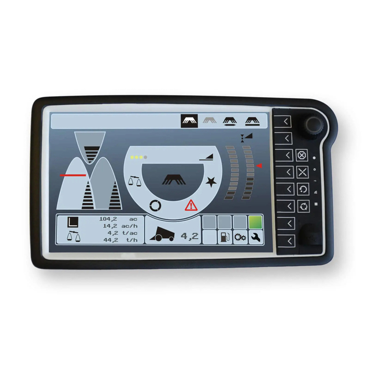
Topcon Athene SM-1 User manual

www.topconpositioning.com
Athene SM-1 Spreader Control
Operator’s Manual


Athene SM-1 Spreader Controller
Operator Manual
Part Number: 1014197-01
Rev Number: 5
For use with Horizon Software Version 5.02
Athene Software Version 3.20
© Copyright Topcon Precision Agriculture
January 2022
All contents in this manual are copyrighted by Topcon. All rights reserved. The information
contained herein may not be used, accessed, copied, stored, displayed, sold, modified,
published or distributed, or otherwise reproduced without express written consent from
Topcon.

ii
This manual provides information about operating and maintaining this
Topcon Precision Agriculture product. Correct use and servicing is
important for safe and reliable operation of the product.
It is very important that you take the time to read this manual before
using the product.
Information in this manual is current at the time of publication. A system
may vary slightly. The manufacturer reserves the right to redesign and
change the system as necessary without notification.
Technical documentation and utility software
On the myTopcon NOW! support website
(mytopconnow.topconpositioning.com) or myTopcon NOW! app you
can access the following support material:
lFirmware and software updates
lProduct manuals
lProduct quick guides
lTraining videos
lSystem layouts
Register for a free account today to access this material.

iii
Table of contents
Chapter 1 – Introduction 1
Chapter 2 – Topcon X-Console Implement Setup 3
2.1. Switching between setup and operation screen 3
2.2. Enabling ISOBUS 4
2.3. Setting up a new vehicle 7
2.4. Selecting an implement 9
2.5. Setting implement geometry 13
2.6. Setting up section control 15
2.6.1. Enabling section control 15
2.6.2. Setting up the section switch 15
2.7. Setting up speed 16
2.8. Opening the Athene UT window 17
Chapter 3 – Athene Setup 19
3.1. Athene primary screens 19
3.1.1. Main screen 19
3.1.2. Spreader settings screen 24
3.1.3. Totals screen 39
3.2. Setting up units 43
3.3. Load cell configuration 44
3.3.1. Can Module 1 configuration 44
3.3.2. Scale Link configuration 46
3.3.3. Load cell calibration 48
3.4. Setting up working width 49
3.4.1. Offsets explanation 49
3.4.2. Setting on and off time 50
3.5. Setting up pre-start 51
3.5.1. Operating pre-start 52
3.6. Setting up border reduction 53
3.6.1. Operating border reduction 54
3.7. Setting up products 55
3.8. Setting up alarms 57
3.9. Setting up forward speed 58
3.9.1. SSF Autocal 58

iv
3.9.2. Simulated speed 59
3.10. Adding product / tare 60
3.10.1. With load cells 60
3.10.2. Without load cells 60
Chapter 4 – Calibration 62
4.1. Product calibration modes 62
4.2. Volumetric calibration (machines without load cells) 64
4.3. Dynamic mode calibration 66
4.3.1. Product flow factor – check calibration routine 68
4.4. Nudge calibration 71
4.5. Valve calibration 72
Chapter 5 – Updating Athene Software 74
5.1. Saving and loading factors 76
5.1.1. To save factors 76
5.1.2. To load factors 76
Chapter 6 – Operation with Topcon Console 78
6.1. Opening auto section control 78
6.2. Variable rate control 80
6.2.1. Source options 81
Chapter 7 – How Dynamic Calibration Works 85
Chapter 8 – Machine Setup Checklist 90
Chapter 9 – Index 91
Chapter 10 – Regulatory and Safety Warnings 92
10.1. Topcon Positioning Systems, Inc. End User License Agreement 101

1
Chapter 1 – Introduction
The Athene spreader controller is an ISOBUS UT-compliant monitoring
and application control system for self-propelled / trailed belt spreaders
spreading lime / granular materials. Forward speed measurement and
cutout sensing enables full proportional control, to maintain (within
limits) a set application irrespective of changes in forward speed.
Shown is a typical retrofitted system (that is independent from the
tractor ISOBUS), utilizing a Topcon X-Console. In this scenario, refer to
Topcon X-Console Implement Setup, page 3 for console setup
instructions.
Some installations will have minor variations, but the key components
are the console, spreader ECU, load cell ECU and load cells. The
system is compatible with an ISOBUS UT compliant tractor terminal. If
using a non-Topcon terminal through ISOBUS, refer to the
manufacturer's manual for setup of the terminal and go to Athene
Setup, page 19 for instructions.
Forward speed sensing may be performed via GPS, or optionally by a
magnetic sensor measuring wheel or propshaft rotation (fitted to the

2
tractor / self-propelled spreader or trailed spreader). The master on/off
switch is ‘virtual’ (a softkey on the Athene operation screen), or
optionally via an external switch mounted next to the operator.
The system may be fitted with or without load cells.
Machines without load cells: The system relies on volumetric calculation
from the known gate height and width, and a known product density. It
works best with relatively free-flowing material of consistent density.
Machines with load cells: Load cells enable fully-automatic, continuous
calibration. They are advantageous for controlling the rate of material
with more variable density at higher rates. By constantly measuring the
weight of product in the spreader, the floor (belt) speed is continuously
adjusted to achieve the correct target application rate. The system
quickly reacts to changes in product characteristics or spreading
conditions without having to adjust or re-calibrate the machine. This
works best with higher rates where weight changes are significant.
Other spreader functions, such as spinner speed, can also be
monitored or controlled, with warnings being triggered if they are not
operating correctly.

3
Chapter 2 – Topcon X-Console Implement
Setup
This chapter explains how to setup and configure the Topcon console
for use with the Spreader Controller features.
Note: If you are using a non-Topcon ISOBUS terminal, go to Athene
Setup, page 19 for instructions.
2.1. Switching between setup and operation
screen
The console has two main screens; the Setup screen and the Operation
screen.
Use the highlighted buttons to switch between the screens.

2.2. Enabling ISOBUS
4
2.2. Enabling ISOBUS
Enables the ISOBUS Universal Terminal server that allows interaction
with the Athene ISOBUS compliant ECU.
To enable ISOBUS / Universal Terminal:
1. Select System /Features /Console .
2. Select FILE SERVER and select Enabled.
3. Select UNIVERSAL TERMINAL and select Enabled.
4. Select System /ISOBUS /UT .
The Universal Terminal setup page is displayed.

Chapter 2 – Topcon X-Console Implement Setup
5
lUniversal terminal: Controls whether the UT server is actively
receiving connections from other devices.
This may be useful if there are multiple UTs on the bus and multiple
UTs claim to be the primary UT (in which case the UT will go offline
automatically and require the UT Number to be changed before it
will go online again), or to temporarily deactivate the UT on the
console.
lUT version: Controls which version of the ISO-11783-6 UT
specification the UT server supports. It is recommended to leave it at
Latest unless problems are encountered in the UT.
lUT number: Sets the UT number for the console. If there are multiple
UTs on the bus, use this setting to assign a unique number to this UT
to avoid conflicts. The UT with number 1 will be the default UT. If the
UT client doesn’t appear on the correct UT you may need to
reconfigure its UT number appropriately. If there is a conflict, the
following message will appear:
'The UT Number of this UT conflicts with another UT on the bus, and
this UT has been disabled. Please make sure that this UT has a
unique UT Number.'
lConfigure Aux-N client behaviour: Enable/disable Aux inputs on this
console. This setting is only relevant if you have more than one UT
connected to the system at the same time (for example an X display

2.2. Enabling ISOBUS
6
and the tractor's UT). If Auto is selected then AUX inputs will be
enabled if Universal Terminal is set to online and the UTnumber is
set to 1.
lClear pool cache: Clears the contents of the UT pool cache. Should
only be used if a UT error is displayed.
lSoft keys per column: Sets the number of available softkeys on the
UT interface on the Operation screen. Note: This should be set to 5
(or 6 if the option to select 5 is not available).
lSoft key location: Sets the location of the softkeys on the UT
interface and the number of columns (1 or 2). Note:Right + Left
should be selected.

Chapter 2 – Topcon X-Console Implement Setup
7
2.3. Setting up a new vehicle
To create a new vehicle profile:
1. Select System /Features /Guidance .
2. Select Auto Steer and select either Enabled for a machine that will
use GPS based Auto Steering or select Disabled for a machine that
will use manual steering or non-GPS row guidance.
The system will warn you that it needs to restart.
3. Select Vehicle /New .
A list of pre-defined factory vehicle templates displays. Templates
contain standard measurements and steering parameter information
where this is available.
4. Select the vehicle manufacturer. Use the scroll bar to see the
complete list. If the required manufacturer is not available, select one
that is most like the vehicle being used. If none of the choices are
appropriate, select Other.
Note: If Other is selected, a list of steering controllers then vehicle
templates displays. Select the most appropriate.

2.3. Setting up a new vehicle
8
5. Select the vehicle model and confirm.
6. To change the name, if required, select VEHICLE NAME, enter the
name and confirm.

Chapter 2 – Topcon X-Console Implement Setup
9
2.4. Selecting an implement
Topcon consoles now allow multiple implements to be connected at the
same time. There can be any number of ISOBUS implement controllers
and ONE specific implement controller with a customized user interface
active at one time. Refer to the X Family Displays Horizon operator
manual for more information.
Athene ISOBUS implement profiles are automatically generated and
made active when an Athene ECU is detected on the bus. These profiles
are shown with 'ISOBUS' at the start of the profile name. The profile will
disappear from the active list if the ECU is disconnected from the bus.
1. To display the active implement profiles, select Implement /
Active .
lISOBUS: Shown next to an automatically detected ISOBUS ECU
present on the bus.
lSelected:Shown next to an implement profile that was manually
created for a specific implement controller.

2.4. Selecting an implement
10
lSelect Implement:Press to select a different implement profile from
the list of manually created implement profiles.
lDisconnected: Shown next to a manually created and selected
profile if the physical implement has been disconnected from the
vehicle.
l
: Shown next to the implement profile selected as the 'primary'
implement. The 'primary' implement is used for guidance (line
recording, swath width, guidelock, steering with offset implements),
boundary recording, Machine Link shared coverage, headland
actions, tramlines and flag point alarms. Highlight the required profile
and select to make it the 'primary' implement. This selection
can not be performed if a task is active or paused, or the vehicle is
currently steering.
l: Can be used to unload a manually created implement profile if
no longer required. Highlight the required profile and select .
Note: The currently active implements are displayed on the Implement
menu.
Selecting the profile on the Implement menu displays the Default task
name option. This enables a default name to be entered for all tasks
performed using the currently selected 'primary' implement. A number
is added to the end of each task name if multiple tasks are performed in
the same field. If a default name is not entered, the task name is derived
from the implement type and current date.

Chapter 2 – Topcon X-Console Implement Setup
11
If the selected implement is pivoted, the Implement model option
displays. This is used to specify whether the 'primary' implement is
actively steered. This setting ensures the Auto Section Control operates
accurately and headland turn shapes are correctly generated.
ISOBUS implement connector type
It is possible that for automatically generated ISOBUS implement
profiles, the ISOBUS ECUs may not specify the correct implement
connector type:
rigid
pivoted (tow behind)
front mount
double pivoted (tow between)
1. To change the selected Connector type, select Implement / profile /
Connector and select from the Connector type drop down list.

2.4. Selecting an implement
12

Chapter 2 – Topcon X-Console Implement Setup
13
2.5. Setting implement geometry
Sets the implement measurements so that guidance can work
accurately.
Note: Measure the implement dimensions as accurately as possible.
The recommended tolerance is +/- 5 cm.
When an ISOBUS implement is connected, some of the geometry items
are provided by the implement and cannot be altered in the console user
interface. Any changes to these must be made in the Athene ISOBUS
UT control screen (see Setting up working width, page 49).
To set the implement geometry:
1. Select Implement /Topcon SM-1 /Geometry .
2. Select an implement dimension. The name of the dimension
appears in the title bar.
Dimensions requested vary according to the type of implement
selected.
3. Add or adjust dimensions where needed and confirm.
Measurements used are as follows:

2.5. Setting implement geometry
14
lSwath Width: Measures the working width of the implement (that is,
the width of the area that is treated during one pass of the
implement).
lWorking Length: Length from the start to the finish of the working
area of the boom. Together with swath width, it defines the ‘Working
Area’, which is the region that product is applied over for that boom.
lOverlap: Measures the width of the overlap between two adjacent
passes.
lImplement Offset: Measures the distance between the hitch point
and the wheels of the implement.
lImplement Wheels Offset: Measures the distance between the
wheels and the working area of the implement.
lInline Offset: Measures the off-center offset of the implement relative
to the hitch point. Enter a positive number if the implement is shifted
to the right and a negative number if it is shifted to the left.
lTrailer Offset: Measures the distance between the trailer hitch point
and the trailer wheels.
lTrailer Wheels Offset: Measures the distance between the
implement hitch point and the trailer wheels.
Table of contents
Other Topcon Controllers manuals

Topcon
Topcon Tesla User manual

Topcon
Topcon X35 User manual

Topcon
Topcon OPUS A3 Eco Specification sheet

Topcon
Topcon KB-50 User manual

Topcon
Topcon ISOBUS Athene - SL2 User manual

Topcon
Topcon ISOCAN User manual

Topcon
Topcon System 350 User manual

Topcon
Topcon T18 User manual

Topcon
Topcon ASC-10 Installation manual
Topcon
Topcon Wachendorff OPUS A8 ECO User manual
Popular Controllers manuals by other brands

Prolific
Prolific PL-2303 Driver installation guide

Hall Research Technologies
Hall Research Technologies CNT-IP-264 user manual

Danfoss
Danfoss EFIT 850 Installation and user manual

BLACK DEVICES
BLACK DEVICES Garage Guardian quick start guide

KONTRONIK
KONTRONIK KOSMIK 160 HV Operation manual

Sealey
Sealey SGA3.V2 instructions