Topcon ISOCAN User manual

500-004-05 UK
ISOCAN / ISOBUS Artemis AS1
Seed Drill Controller
Installation Manual


1
Electromagnetic Compatibility (EMC)
This product complies with European Council Directive 2014/30/EU when installed and used in accordance with the
relevant instructions.
Preface
This manual provides information about installing the RDS “ISOBUS Artemis” system. Correct use and maintenance is important for safe and reliable
operation. Please take time to read this manual and complete appropriate training before using the system.
Information in this manual is correct at the time of publication. The system may vary slightly from that described herein. Topcon reserves the right
to redesign and change the system as necessary without notification.
COPYRIGHT: All information contained in this manual is the intellectual property and copyrighted material of Topcon. All rights are reserved. You
may not use, access, copy, store, display, create derivative works of, sell, modify, publish, distribute, or allow any third parties access to, any
graphics, content, information or data in this manual without Topcon’s written consent. And may only use such information for the care and
operation of the product.
Warning
Please read the following important information very carefully.
TERMS AND DEFINITIONS:
Console – The Topcon Agriculture console mounted inside the cab of the tractor used for primary control of the Machine.
Application – Topcon Agriculture mobile application product that allows features of Topcon Console(s) to be monitored and controlled from a
Device.
Device – A mobile device (e.g. phones and tablets) on which the Application is installed and operated.
System – The combination of the Device and the Console used to control and monitor the Machine.
Machine – The combination of a tractor and associated farming implements (whether self-propelled, towed by the tractor or mounted to the
tractor).
You – The person using the application to control and monitor the Machine.
Device – A mobile device (e.g. phones and tablets) on which the Application is installed and operated.
Documentation – The user documentation and manuals relating the use and operation of the covered Topcon Agriculture product, including, but
not limited to, the Console user manuals/materials and Application end user license agreement.
IMPORTANT: You must read and follow the Documentation and complete appropriate training before use. If You do not operate the System
properly, it may not correctly apply the Application to Your requirements. This can result in damage to property and/or malfunction of the product,
death or serious injury to persons, poor yields and/or crop damage or failure. If You are in any doubt regarding any aspect of operating the System,
then before commencing operation You should obtain further guidance from a suitably qualified source.
WARNING: It is YOUR responsibility to read and understand the safety sections in this book before operating the system. Remember
that YOU are the key to safety.
PRODUCTS/MATERIALS APPLICATION: As limited by the applicable software, You are responsible for accurately entering the information required
for the Machine to apply products/materials to Your requirements, including measurement units (e.g. metric or Imperial), vehicle dimensions, rate
of application, vehicle speed, weight or other required input.
As limited by the applicable software, You are responsible for the calibration of the Machine and ensuring products/materials are applied in
accordance with their specifications (including wind, temperature and moisture conditions, material properties, dilution and withholding periods).
Without prejudice to the generality of the above You hereby acknowledge and agree that the system or application is not designed nor intended to:
originate variable treatment plans; or
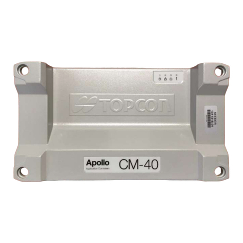
achieve or avoid any application rate or other target setting outside application parameters, which in both cases are Your
responsibility.
Failure by You to comply with the above may result in incorrect operation of the System, or injury to You or others. You should monitor at all times
that the System is performing as required.
General Safety
DANGER! It is essential that the following information and the product-specific safety information is read and understood.
Most incidents arising during operation, maintenance and repair are caused by a failure to observe basic safety rules or precautions. Always be alert
to potential hazards and hazardous situations. Always follow the instructions that accompany a Warning or Caution. The information these provide
aims to minimize risk of injury and/or damage to property. In particular follow instructions presented as Safety Messages.
ISOCAN / ISOBUS ARTEMIS - SEED DRILL CONTROLLER
2
Safety Messages and Warnings
The safety symbol is used with the relevant word : DANGER, WARNING or CAUTION. Messages marked in this way recommend safety precautions
and practices. LEARN and apply them.
DANGER : Indicates an imminently hazardous situation that, if not avoided, could result in DEATH OR VERY SERIOUS INJURY.
WARNING : Indicates a potentially hazardous situation that, if not avoided, could result in DEATH OR SERIOUS INJURY.
CAUTION : Indicates a potentially hazardous situation that, if not avoided, could result in MINOR INJURY.
Operator Safety
Good safety practices not only protect you, but also the people around you. Study this manual as part of your safety program. This safety
information only relates to Topcon equipment and does not replace other usual safe work practices.
WARNING: Never operate the machine with any panels or safety guards removed. Any illustrations or photos in this manual that
show panels or guards removed are solely for demonstration purposes. If the removal of panels and guards is necessary for
calibration or maintenance, they MUST be replaced before operation.
Always check that any suspended vehicle attachments or load arm(s) are lowered to the ground before beginning repair or
maintenance work on the machine.
Machine and implement parts can become hot during operation and may be under pressure. Refer to the machine/implement
manual(s).
Wear appropriate protective clothing for the task being undertaken.
Check the Machine is correctly setup/configured and ready for the intended use.
Be aware of safety instructions for/on the Machine including hazards such as crush zones.
Prevent the Machine from being accidentally started if working on it e.g. remove the ignition key, place a warning notice in the cab
etc.
Check that the area of Machine operation is clear of people, animals, and obstacles and identify any other possible hazards.
Keep other persons required to be in the vicinity of the Machine fully aware of Your immediate intentions.
If a Topcon Agriculture mobile application is used to augment Your ability to perform tasks that are traditionally performed on the Console directly,
then in addition to observing the above warnings and all other pre-determined site safety requirements that apply when operating a Machine from
the Console, You must also observe the following additional requirements when operating the Machine via the Application:
WARNING: The Application must only be operated by You, the single Console operator wholly responsible for the operation of the
Machine.
The Application must only be used when the Machine is not on public roads.
The Device must be affixed to a rigid mount when used inside the cab while the Machine is moving to avoid a temporary loss of
control if the Device is dropped or misplaced.
The Application must only be used outside of the Machine cab when the Machine is stationary.
When operating the Application outside of the cab of the Machine You must remain within a reasonable distance such that You can
return to the cab-mounted Console in a timely manner to resume control of the Machine under any of the following circumstances:
Battery failure on the Device
Wifi signal is lost or signal strength is too weak for proper operation
The Device is redirected to another application (e.g. a phone call is received)
The Device becomes incapacitated (e.g. device is dropped and damaged)
Any other event that causes the Device to no longer be fit for control of the Application and/or Machine.
Stand well clear of any moving parts of the Machine (e.g. hydraulic folding booms, spreader spinners, etc.) and areas of product
application (e.g. Spray Nozzles, NH3 appliers, etc.).
The Device and Machine must be locked when not in use.
The Device and Machine must never be left unattended.

ISOCAN / ISOBUS ARTEMIS - SEED DRILL CONTROLLER
3
1. OVERVIEW 5
1.1 Standard Kits 5
1.2 Drill Configurations and Kits required 5
1.3 Basic ISOCAN Single-motor system Schematic 6
1.4 Basic ISOBUS Single-motor system Schematic 7
1.5 2, 3 and 4-motor systems Schematic 8
1.6 Extension Cable Kit Ref. P/ART2/EXT/4M (option for trailed drills) 8
1.7 Parts List 9
2 MOTOR 12
2.1 Motor 12
2.1.1 Motor rotation ............................................................................................................................................. 13
2.1.2 Motor Connections ...................................................................................................................................... 13
3 MOTOR CONTROL MODULE AND SENSORS 14
3.1 MCM mounting 14
3.2 Power Supply 14
3.3 Motor and MCM 0V connection and Grounding 14
3.4 MCM Control channel setup 16
3.5 Priming Switch 16
3.6 Seed Shaft Confirmation Sensor 17
3.7 Metering unit setup 17
3.8 Hopper Level sensors 18
3.8.1 Hopper level sensor configuration ............................................................................................................... 18
4 ECU AND SENSORS 19
4.1 Fan Speed Sensor 19
4.2 Area Cutout / Lift-Lower / Tramline advance 19
4.2.1 Area cutout / Tramline advance................................................................................................................... 19
4.2.2 Lift-Lower installation ..................................................................................................................................20
4.2.3 Tramline Module Configuration................................................................................................................... 20
4.2.4 Area cutout / Lift-Lower / Tramline advance configuration......................................................................... 21
4.3 Forward Speed Input 21
4.3.1 Satspeed 2.................................................................................................................................................... 21
4.3.2 GPS / ISOBUS................................................................................................................................................ 22
4.4 Tramline Mechanisms 23
4.4.1 Motor-type Tramline mechanisms............................................................................................................... 23
4.4.2 Solenoid-type Tramline mechanisms` .......................................................................................................... 24
5 WIRING 25
5.1 MCM – Expansion Harness and Sensors 25
5.1.1 Setting the MCM ID...................................................................................................................................... 26
5.1.2 Expansion Harness (S/TC/1015540-01) Wiring Table................................................................................... 26
5.2 ISOBUS Artemis ECU (AS1) 27
5.2.1 ISOBUS Artemis ECU (AS1) Wiring Table ...................................................................................................... 28

ISOCAN / ISOBUS ARTEMIS - SEED DRILL CONTROLLER
4
6 BLOCKAGE MONITORING 29
6.1 Single product setup (Kit: P/BLOCK/SIN) 29
6.2 Dual-product setup (Kit: P/BLOCK/DUAL) 30
6.3 Sensors 30
6.3.1 Sensor and Row numbering ......................................................................................................................... 31
6.4 Blockage sensor configuration 31
6.4.1 Enable blockage monitoring functions......................................................................................................... 31
6.4.2 ECU Setup .................................................................................................................................................... 31
6.4.3 Sensor Setup ................................................................................................................................................ 32
6.4.4 Diagnostics................................................................................................................................................... 32

ISOCAN / ISOBUS ARTEMIS - SEED DRILL CONTROLLER
5
1. Overview
NOTE: Screenshots ilustrated in in this manual may be either as displayed on an ISOCAN, or a Topcon UT, however although the
softkey layout may differ, the menus and functionality are otherwise the same.
1.1 Standard Kits
Various standard kits are available independently or in combination, that enable the Artemis system to be adapted for
almost any drill configuration. The kits are as follows,
P/ART3/ISOCAN
Full kit with motor for a single-motor system with an ISOBUS-compatible RDS “ISOCAN”
Artemis head unit.
P/ART3/ISOBUS
Full kit with motor for a single-motor system connecting to the tractor ISOBUS socket,
utilising the tractor ISOBUS UT.
P/ART3/ISOBUS/NM
Kit as above but without motor (for utilising an existing motor).
For a single-motor system connecting to the tractor ISOBUS socket, utilising the tractor
ISOBUS UT.
P/ART3/2ND
Kit for installing an additional motor.
Required for each additional control channel (Seed / Fert.)
P/ART3/2ND/NM
Kit as above but without motor (for utilising an existing motor).
Required for each additional control channel (Seed / Fert.)
1.2 Drill Configurations and Kits required
The following table shows some common configurations of an Artemis system and the kits required.
PRODUCT
CHANNELS
PRODUCT /MOTOR / METERING UNIT
CONFIGURATION
KITS REQD
SCREEN DISPLAY
SEED
1
1 PRODUCT
SINGLE MOTOR / METERING
P/ART3/ISOCAN
1+2
1 PRODUCT
2 x SINGLE MOTOR / METERING
P/ART3/ISOCAN
P/ART3/2ND
1
2
2 PRODUCTS
SINGLE MOTOR / METERING (SEED)
SINGLE MOTOR / METERING (FERT)
P/ART3/ISOCAN
P/ART3/2ND
SEED
+
FERTILISER
1+2
3+4
2 PRODUCTS
2 x SINGLE MOTOR / METERING (SEED)
2 x SINGLE MOTOR / METERING (FERT)
P/ART3/ISOCAN
P/ART3/2ND (x3)
SEED
+
FERTILISER
1+2
3
2 PRODUCTS
2 x SINGLE MOTOR / METERING (SEED)
SINGLE MOTOR / METERING (FERT)
P/ART3/ISOCAN
P/ART3/2ND (x2)
1
2
3
3 PRODUCTS
SINGLE MOTOR / METERING (SEED)
SINGLE MOTOR / METERING (FERT)
P/ART3/ISOCAN
P/ART3/2ND (x2)
SEED
+
FERTILISER
1+2
3
4
3 PRODUCTS
2 x SINGLE MOTOR / METERING (SEED)
SINGLE MOTOR / METERING (FERT)
P/ART3/ISOCAN
P/ART3/2ND (x3)

ISOCAN / ISOBUS ARTEMIS - SEED DRILL CONTROLLER
6
1.3 Basic ISOCAN Single-motor system Schematic
Kit Ref. : P/ART3/ISOCAN
Figure 2
‘MCM’ CAN
Module
Motor
Priming Switch
Area Cutout/ TL
Advance
Seed Shaft 1
Confirmation
Sensor
S/TC/1015540-01
Expansion Harness
Tramline actuators
(not supplied by
Topcon)
Hopper level 1
sensor
11
S/CB/411-1-026
Seed blockage
sensors
(optional)
S/HU/410-3-002
Satspeed 2
ECU
Assembly
S/CB/410-3-020
Fan 1 Speed
Sensor
42
46
49
43
55
51
45
49
44
52
50
48
41
20
13
(Ref. Figure 4)
B
10
K/ART2/PWR
Seed Shaft 2
Confirmation Sensor
(optional)
Hopper level 2 sensor
(optional)
Fan 2 Speed
Sensor
(optional)
Lower Area Cutout
(optional)

ISOCAN / ISOBUS ARTEMIS - SEED DRILL CONTROLLER
7
1.4 Basic ISOBUS Single-motor system Schematic
Kit Ref. : P/ART3/ISOBUS or P/ART3/ISOBUSNM (Motor not included)
Figure 3
Isobus Cab Harness
(not included)
‘MCM’ CAN
Module
Motor
Priming Switch
Area Cutout/ TL
Advance
Seed Shaft 1
Confirmation
Sensor
S/TC/1015540-01
Expansion Harness
Tramline actuators
(not supplied by
Topcon)
Hopper level 1
sensor
40
S/CB/500-1-156
Seed blockage
sensors
(optional)
ISOBUS UT
(not included)
Satspeed 2
ECU
Assembly
S/CB/410-3-020
Fan 1 Speed
Sensor
42
46
49
43
55
51
45
49
44
52
50
48
41
20
13
(Ref. Figure 4)
B
K/ART2/PWR
Seed Shaft 2
Confirmation Sensor
(optional)
Hopper level 2 sensor
(optional)
Fan 2 Speed
Sensor
(optional)
Lower Area Cutout
(optional)

ISOCAN / ISOBUS ARTEMIS - SEED DRILL CONTROLLER
8
1.5 2, 3 and 4-motor systems Schematic
Kit Ref.: P/ART3/2ND (with motor) or P/ART3/2NDNM (Motor not included)
For multi-channel systems, 1, 2 or 3 additional motor kits are daisy-chained via connectors ‘B’ and ‘C’ of the Expansion
Harness ref. Pt No. S/TC/1015540-01.
Figure 4
1.6 Extension Cable Kit Ref. P/ART2/EXT/4M (option for trailed drills)
A 4m extension cable kit for use with trailed drills.
Figure 5 : Kit Ref. P/ART2/EXT/4M : Cable Extension Kit.
Item #
Part No.
Description
Qty
70
S/CB/318-1-022
Power Supply Extension Cable – 4m
1
71
S/CB/318-1-021
Instrument Extension Cable – 4m
1
‘MCM’ CAN
Module
B
C
B
C
S/TC/1015540-01
Expansion Harness
Motor
Priming Switch
Seed Shaft 1
Confirmation
Sensor
Hopper level 1
sensor
46
45
49
44
52
50
48
Seed Shaft 2
Confirmation Sensor
(optional)
Hopper level 2 sensor
(optional)
71
70

ISOCAN / ISOBUS ARTEMIS - SEED DRILL CONTROLLER
9
1.7 Parts List
Item #
Part No.
Description
Qty
P/ART3/ISOCAN
P/ART3/ISOBUS
P/ART3/ISOBUSNM
P/ART3/2ND
P/ART3/2NDNM
Tractor-based components (Figure 6)
10
S/HU/410-3-002
Isocan Head Unit
1
11
S/CB/411-1-026
Isocan Head Unit Cable
1
12
K/ISOCAN/MTG/KT
Isocan Mounting kit
1
13
S/CB/500-1-074
Power Cable - Tractor
1
1
1
Implement High-current Power Supply components (Figure 7)
20
K/ART2/PWR
Power Cable kit comprising :-
1
1
1
21
S/FR/500-6-064
M5 x 25 Hex. Set Screw
3
3
3
22
S/FSNR/940204
M5 Flat Washer
6
6
6
23
S/FR/500-6-051
M5 Nut
3
3
3
24
S/CB/268-6-021
Power Cable (5-metre) - Implement
1
1
1
25
S/W684-015
1-metre 14G Wire – Black
1
1
1
1
1
26
S/W684-016
1-metre 14G Wire – Red
1
1
1
1
1
27
S/H663-025
Fuse – 60 Amp
1
1
1
28
S/H661-012
Fuse Holder
1
1
1
29
S/T610-111
Wire Terminal - D25-6
2
2
2
30
S/T609-071
Wire Terminal – Yellow Ring
8
8
8
4
4
Implement-based components (Figure 8)
40
S/CB/500-1-156
ISOBUS Cable
1
1
41
S/CB/410-3-020
ISOBUS Extension Lead c/w CAN
1
1
1
42
S/AC/410-3-012
Type E ECU
1
1
1
43
S/SR/385-2-006
Satspeed 2 GPS Interface
1
1
1
44
S/TC/1015540-01
Expansion Harness (2 / 3 / 4-Motor)
1
1
1
1
1
45
S/AC/322-9-001
CAN Module – MCM
1
1
1
1
1
46
S/AC/268-6-043
Motor Assembly
1
1
1
47
S/AC/500-4-083
Motor Shaft
1
1
1
48
S/SR/201-2-006
Capacitance Sensor - Hopper Level
1
1
1
1
1
49
S/SR/500-2-107
Magnetic Sensor (Seed Shaft Confirmation / Fan Speed)
2
2
2
1
1
50
S/SW/500-7-019
Priming Switch
1
1
1
1
1
51
S/MG/185/1/013
Magnet - Fan Speed
1
1
1
52
S/MG/289-1-010
Magnet - Shaft Speed Confirmation
1
1
1
1
1
53
S/FR/500-6-051
M5 Nyloc Nut
15
15
15
8
8
54
S/FR/500-6-064
M5 Bolt
10
10
10
5
5
55
S/SW/500-7-018
Finger Switch
1
1
1
56
S/FSNR/940204
Washer
15
15
15
8
8
57
S/CB/322-5-013
MCM Earthing Strap
2
2
2
1
1

ISOCAN / ISOBUS ARTEMIS - SEED DRILL CONTROLLER
10
Figure 6 : Tractor-based components
Figure 7 : Implement High-current Power Supply components
K/ART2/PWR
10
11
12
13
21
22
23
24
25
26
27
28
29
30

ISOCAN / ISOBUS ARTEMIS - SEED DRILL CONTROLLER
11
Figure 8 : Implement-based components
40
41
42
43
44
45
46
47
48
49
50
51
52
53
54
55
56
57
49

ISOCAN / ISOBUS ARTEMIS - SEED DRILL CONTROLLER
12
2 Motor
On a dual-motor installation, the left motor is connected to a motor control module designated MCM-1, and the right
motor to motor control module designated MCM-2. In this case, make sure the motor encoder cables are routed to the
correct module.
2.1 Motor
Figure 9 : Motor mounting dimensions
Figure 10: Motor driving single metering unit
Remove the landwheel drive shaft, and mount the
motor [46] in line with the metering unit input
shaft. The metering unit must be driven as per the
land drive connection point otherwise any half
width clutch (if fitted) may not function correctly.
Fit the shaft [47] to the appropriate side of the gearbox.
Shorten or otherwise modify the existing landwheel
drive shaft/coupling as necessary, to connect the
motor drive shaft to the metering unit. Ref. Fig. 9
for motor shaft dimensions
NOTE: Ensure sufficient space to install the Seed Shaft Sensor
(section 3.5).
Route the cable back to the MCM.
Figure 11: Motor driving two metering units
A suitable motor shaft is available on request -
please contact the factory.
If updating the machine from a land wheel system,
it may be worth marking on the metering unit which
direction the metering unit turns when the land
wheel is being driven forward.

ISOCAN / ISOBUS ARTEMIS - SEED DRILL CONTROLLER
13
Due to design variations between drill makes and models, it is not possible to supply mounting brackets or motor drive
shaft components to guarantee universal fitment. The installer must arrange/provide:
Suitable mounting bracket for the motor
Drive shaft/coupling to go between motor and metering unit
Any other necessary brackets i.e. for seed shaft confirmation sensor(s)
2.1.1 Motor rotation
Looking at the motor as shown, it turns CLOCKWISE
with the red wire to 12V and the black wire to 0V.
Simply reverse the connections onto the MCM to
rotate in the opposite direction.
2.1.2 Motor Connections
Each motor is connected to a Motor Control Module as shown.
NOTE: The motor cable is approx. 1.8m (6 feet) long. Please ensure that the proposed mounting positions for the motor(s) and
MCM(s) allows the cable(s) to reach!
Figure 13
[1] Grounding where MCM is 0.5m or closer from chassis grounding point
[2] Grounding where MCM is further than 0.5m from chassis grounding point
RED TO 12V
BLACK TO 0V
Master Grounding Point
(Ref. section 3.3)
0V Supply
+V
Sup
ply
Motor +V
Motor 0V
Ground [1]
Ground [2]
RED
BLACK
RED
BLACK
YELLOW/GREEN
YELLOW/GREEN
+V Supply
+V
Sup
ply

ISOCAN / ISOBUS ARTEMIS - SEED DRILL CONTROLLER
14
3 Motor Control Module and Sensors
NOTE: For multi-channel installations, ensure the Seed Shaft Confirmation sensor(s), Hopper Level sensor(s) and Priming switch
are connected to the appropriate Expansion Harness.
3.1 MCM mounting
The MCM modules are sealed and it is not essential to mount them inside another enclosure for protection against the
elements. However, a box-type cover or enclosure will offer more protection from pressure washing or physical
damage, and make the installation look neater.
The MCM modules [45] should if possible be grouped centrally, mounting them on a single mounting plate that is
grounded to the chassis via a central ‘Master Grounding point’ (fig.14). observing that,
the sticker is facing out and cable connection points are at the bottom.
the motor drive wires can be easily connected onto the module,
the motor encoder cable can connect onto connector ‘A’ of the Expansion Harness S/TC/1015540-01.
Mount them using the M5 Set Screws [21], Flat Washer [22] and Nut [23].
MAKE THE CONNECTIONS ONTO THE STUDS WITH FLAT WASHERS EITHER SIDE OF THE TERMINAL(S) AND M5 NUT.
Ensure all connections are tight and that there is no possibility of them shorting together. It is advisable to coat the
studs with petroleum jelly or an equivalent.
NOTE: The motors direction of rotation will be dependant upon which way it is connected to the MCM. If the direction of rotation
is incorrect simply reverse the connections.
The yellow/green wire fitted to the motor should be connected onto the grounding point (ref. Section 3.3).
3.2 Power Supply
Route the Tractor Power Cable [13] direct from the battery to the rear of the tractor (or to the front for a front-
mounted hopper).
Route the Implement Power Cable [24] to a point central to the MCM modules. Mount the Fuseholder [28]. Cut the
red wire to length and connect to the fuseholder using terminal [29].
3.3 Motor and MCM 0V connection and Grounding
NOTE: Fan operation particularly in dry conditions, can generate extremely high-voltage static charge. Therefore, it is
ESSENTIAL to install the Yellow/Green ground wiring and Black 0V wiring as instructed, to help protect the system
against electro-static discharge (ESD).
Providing modules are located in close proximity to each other (e.g. less than 500mm), then the Module 0V wires [25]
and Motor earth wires can be connected directly to a ‘Master Grounding point’ (ref. figure 14).
If the modules are NOT located in close proximity to each other (e.g. MORE than 500mm), then the Module 0V wires
[25] are still connected to the ‘Master Grounding point’, however, you MUST ALSO establish a reliable chassis grounding
point locally next to each Module.
The Motor earth wire is then connected to the local grounding point, and also a separate Earth Strap [57] must be
connected between the local grounding point and the 0V stud on the adjacent Module (ref. Figure 15).
Establish a reliable ‘Master Grounding point” on the chassis using M5 Set Screw, Washers and Nut [21,22,23], and
connect the master 0V wire using terminal [29]. Using a multimeter, check continuity between the wire terminal and
chassis is acceptable. The grey rectangle in figure 14 suggests a metal mounting plate for the modules but can also be
the chassis of the drill.
Using the black wire [25] and crimps [30] supplied, connect separate 0V wires between the ‘Master Grounding point’
and the 0V stud on each module.
Using the red wire [26] and crimps [30] supplied, connect separate +V wires between the Fuseholder [28] and the +V
stud on each module.

ISOCAN / ISOBUS ARTEMIS - SEED DRILL CONTROLLER
15
Figure 14: Connections when modules are less than 500mm from a master grounding point on chassis
Figure 15: Connections when modules are more than 500mm from a master grounding point on chassis
[13]
[28]
[26]
[26]
MCM-2
[29]
MCM-1
[24]
[29]
[25]
[25]
MASTER
GROUNDING POINT
[13]
[26]
[26]
MCM-1
[29]
[28]
[29]
[25]
[24]
MASTER
GROUNDING POINT
MCM-2
[25]
[57]
[24]
Expansion Harness S/TC/1015540-01
LOCAL
GROUNDING
POINT
LOCAL
GROUNDING
POINT
[57]
Expansion Harness S/TC/1015540-01

ISOCAN / ISOBUS ARTEMIS - SEED DRILL CONTROLLER
16
3.4 MCM Control channel setup
Setup in the Artemis app as follows.
1. Cycle to the ‘Setup’ screen, touch the tab and select “Channel Setup”
2. Select the control channel for each motor in turn,
“Metering unit” Indicates the selected channel.
“In Use” Set to “Yes” to enable a channel (sequentially i.e. 1,2 , 1,2,3 , or 1,2,3,4).
“Width” Set the working width in metres. If separate left and right motors are installed utilising 2 channels,
each channel would be set to half the full working width.
“Linked” When a configuration requires multiple hoppers / metering units to dispense a single product, then
the control channels are linked.
Two, three or four single, adjacent control channels may be linked in this way.
Examples:
“Product” Assigned a product type “Seed”, “Fert A”, “Fert B etc.
“Module Type” Should be “MCM”
3.5 Priming Switch
Part Ref. S/SW/500-7-019
For each motor channel, the priming switch manually operates the motor to dispense product for calibration purposes.
Mount the switch [50] where convenient for calibration. Route the cable back to connector ‘H’ of the Expansion
Harness S/TC/1015540-01 for that motor.
UK863-780.PNG
UK863-620.PNG

ISOCAN / ISOBUS ARTEMIS - SEED DRILL CONTROLLER
17
3.6 Seed Shaft Confirmation Sensor
For each motor channel, the Seed Shaft Sensor provides confirmation that the motor is driving the metering unit.
Fit the magnet carrier [52] on the metering unit input shaft. Mount the sensor [49] adjacent to the magnet by suitable
means. Note the magnet-sensor position as shown in fig. 17. Route the cable back to connector ‘F’ of the Expansion
Harness S/TC/1015540-01 for that motor.
Figure 16 : Seed Shaft Sensor Figure 17: Magnet-Sensor position
6
In the case of a single motor driving two metering units, a 2nd Seed Shaft Confirmation Sensor may be plugged into
connector ‘G’ of the Expansion Harness S/TC/1015540-01 for that motor.
3.7 Metering unit setup
The only setting that may require changing from the factory default value is the PPR value for the seed confirmation shaft
sensor.
Setup in the Artemis app as follows.
1. Cycle to the ‘Setup’ screen, touch the tab and
select “Metering unit Setup”
2. Select the MCM channel.
3. Select “Shaft 1” and set the ppr equal to the number of
magnets on the magnet ring fitted. If no sensor is fitted,
then set to zero.
4. Press ESC to return to the “Setup” screen.
5. Repeat steps 2 and 3 for additional motor channels.
NOTE: The other metering unit settings do not normally need to be changed.
Sensor
1
0
2
0
[52]
[49]
20mm
10mm
UK863-670.PNG

ISOCAN / ISOBUS ARTEMIS - SEED DRILL CONTROLLER
18
3.8 Hopper Level sensors
Depending on the drill configuration, for each channel in use there can be either,
(i) a single low-level sensor (sensor ‘1’).
(ii) Both a low-level sensor and an upper “Pre-Level” level sensor
(sensor ‘2’). The additional “pre-level” sensor is positioned
higher up in the hopper to provide the operator a more
advanced warning.
Mount the sensor(s) [48] either through the tank wall (requires
a 27mm hole) or inside the tank at the appropriate height(s). If
the sensor is mounted inside the tank, the height can if
necessary, be adjusted e.g. to suit different products.
Route the cable(s) back to connector ‘E’ (for sensor ‘1’) and connector ‘D’ (for sensor ‘2’) of the Expansion Harness
S/TC/1015540-01.
For multi-channel systems where level sensors are installed for each channel (product), all sensors (8 in total for a 4-
channel system), then these are connected to their respective Expansion Harness S/TC/1015540-01 for MCM-2, MCM-3,
and MCM-4.
Wire Colour
Function
Brown
+V
Blue
0V
Green/Yellow
Signal
3.8.1 Hopper level sensor configuration
Setup in the Artemis app as follows.
1. Cycle to the ‘Setup’ screen, touch the tab and select “Channel Setup”.
2. Select the channel.
3. Scroll to “Level Sensor” and “Pre-Level Sensor”.
4. For each, set “Direct Input”.
5. Press ESC and then to return to the operating screen.
Height-Adjustable bracket (not supplied)
Sensor [19]
UK863-620.PNG
U
K
8
6
3
-
7
8
0
.
P
N
G
UK863-780.PNG
This manual suits for next models
2
Table of contents
Other Topcon Controllers manuals

Topcon
Topcon OPUS A3 Eco Specification sheet

Topcon
Topcon T18 User manual

Topcon
Topcon KB-50 User manual

Topcon
Topcon ISOBUS Artemis User manual

Topcon
Topcon Athene SM-1 User manual

Topcon
Topcon FC-2500 User manual

Topcon
Topcon Tesla User manual

Topcon
Topcon X35 User manual

Topcon
Topcon Norac UC5 User manual

Topcon
Topcon Liquid Systems CM-40 User manual