Bernhard Rapid Facer User manual

1
© Bernhard and Company Limited
RAPID FACER MANUALRAPID FACER MANUAL
RAPID FACER
User Guide &
Instruction Manual
Please read this manual carefully before using the Rapid Facer.
This manual should be kept in a safe place for future reference.
RF1000 Bedknife Front Facing Device

2
RAPID FACER MANUAL
RAPID FACER
Contents
RF1000 Bedknife Front Facing Device
Welcome to the Bernhard Rapid Facer (RF1000). If cared for and operated
correctly this machine will give you years of good service.
This manual will enable you to obtain the best results from your Rapid Facer so
please read it thoroughly before using your machine.
If you have any service or operational issues please contact your distributor or
phone our technical support hotline
Technical Helpline (USA only) 1-888 474 6348
Rest of World: UK Head Oce, England (+44) 1788 811600
Email: support@bernhard.co.uk
Technical FAQs can be found on our web site: www.bernhard.co.uk
When ordering spare parts please quote the machine type and serial number.
THE MANUFACTURERS ACCEPT NO RESPONSIBILITY FOR ANY SITUATION ARISING FROM THE
FITTING AND/OR USE OF NON-ORIGINAL SPARE PARTS.
Overview 3
Safety 4
Description 5
On-site / Workshop Requirements 5
Setting Up 6
Operation 9
Maintenance 11
Repairs 11
Part Numbers and Reference Diagrams 12
Rapid Facer – ENG/1040.4/RB
Please quote this serial number on all
correspondence:
Serial #:
BERNHARD AND COMPANY LIMITED
Bilton Road • Rugby • England • CV22 7DT
Tel +44 1788 811600 • Fax +44 1788 812640
Email: [email protected]
USA Toll Free 1-888 GRIND IT (1-888 474 6348)
3
© Bernhard and Company Limited
RAPID FACER MANUAL
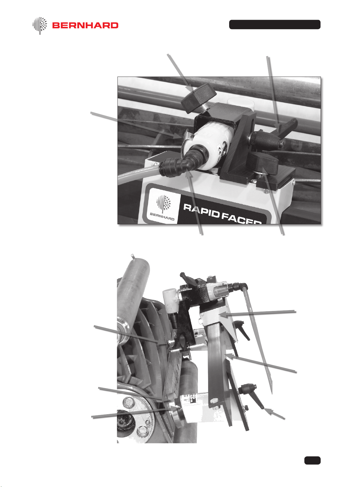
Angle grinder locking screw
Grinder trigger
Swivel elbow air-line tting
Grinder head height
adjust
Grinder head 'in-out' adjust
Magnetic clamp
Eccentric ne
height adjust Height adjust
lever
Grinding
carriage
Grinding
slide rail
Two reel guide
pins on either
side of grinding
disc

4
© Bernhard and Company Limited
RAPID FACER MANUAL
1.1 IMPORTANT
The air supply must NOT be connected when:
a) attaching the Rapid Facer RF1000 to the bedknife
b) setting up the Rapid Facer RF1000
c) removing the Rapid Facer RF1000 from the bedknife.
WARNING: THE MAGNETS ARE VERY POWERFUL
1.2 Always support the angle grinder carriage whilst carrying the Rapid Facer RF1000.
Do NOT hold the Rapid Facer RF1000 by the magnets when attaching the machine to the
bedknife.
1.3 Always wear eye protection when operating the Rapid Facer RF1000
1.4 When operating the Rapid Facer RF1000 never:
a) leave rags or tools on the machine
b) wear loose clothing that could become caught in the grinding disc or chuck.
Always keep long hair tied back.
1.5 The disc causes hot sparks. Make sure no ammable materials are close.
1.6 Never use the machine for any purpose other than that for which it is designed.
1.7 Always use the correct grinding discs.
1.8 Never t a disc while the air line is connected.
1.9 Never use the Rapid Facer RF1000 when the cutting unit is set up on a Reel Grinder.
1.10 We advise the wearing of ear defenders.
1.11 Keep your ngers clear of the reel blades when operating the Rapid Facer RF1000.
1.12 The air grinder must not be removed from and used independently of the tool holder.
1. Safety

5
© Bernhard and Company Limited
RAPID FACER MANUAL
2. Description
2.1 The Rapid Facer RF1000 consists of an air driven angle grinder attached to an accurate
slide rail. This is xed to the base of a bedknife by two powerful magnets. It is used to
grind the front face of the blade to sharpen it.
2.2 The angle grinder carriage is attached to the slide rail supported on rollers. These are
adjustable to reduce backlash to a minimum. The rollers also allow the grinding head to
traverse along the rail. The grinding head produces an accurately ground cutting edge on
the bedknife. This cutting edge will also be parallel to the rotational axis of cutting reel.
2.3 The adjustable handle (part 15) allows the grinding disc to be set for a wide choice of
clearance angles on the front face of the bedknife.
2.4 Two reel pins (part 39) are attached to the grinder carriage. These deect the reel blades
and allow the disc to sharpen the bedknife without damaging the reel blades.
2.5 As with other Bernhard reel and bedknife grinding machines this grinding action takes
place where the grass is cut. This is the key to the excellent results produced by our
equipment.
3. On-Site
/
Workshop Requirements
3.1 AIR SUPPLY
Consistent with industry ‘Best Practice’, Bernhard recommend that the air supply for ALL
air powered tool is tted with:
• An in-line air lter and water separator • An in-line lubricator
for trouble-free service life of the Rapid Facer.
If water gets into the tool and it will lay there whilst the tool is not is use, and may result in
corrosion which may cause seizure. This may invalidate your warranty.
It should be supplied to the air motor by a securely attached exible hose which allows free
movement of the grinding head along the slide rail.
3.2 AIR FLOW RATE
The air motor operates best on an airow rate of 9 cubic feet/min. (0.25 cubic metres/min).
The air motor is designed for a maximum air pressure of 6 bar (90 psi).
3.3 An isolating valve must be available to cut o the air supply to the machine. This must be
sited close to the machine.
3.4 It is useful to have a pressure regulator in the air line.

6
© Bernhard and Company Limited
RAPID FACER MANUAL
4. Setting Up
4.1 NOTE: The Rapid Facer RF1000 as shipped will need some minimal assembly before use.
4.2 PRELIMINARY CHECKS
4.2.1 Ensure that the air supply is not attached to the angle grinder motor.
4.2.2 Ensure that the eccentric pillars (parts 23 & 24) are correctly adjusted. They are set to
reduce backlash and allow free movement of the grinding head along the rail. These are
preset on new machines.
4.2.3 Ensure that the correct grade and size of grinding of disc (part 42) is tted to the angle
grinder. This is factory supplied.
4.2.4 Ensure that the grinding disc (part 42) is concentric with the disc holder (part 41). This is
factory set.
4.2.5 Ensure that the grinding disc (part 42) is securely attached and that neither the disc nor the
disc holder (part 41) are damaged.
4.2.6 Ensure that the angle grinder (part 40) is securely attached to the carriage. Check that the
disc is set between the reel pins (part 39) and is free to rotate.
Mount Plate / Magnet assemblies
to rail, coloured dot facing coloured
dot as shown above.
Socket cap screws may be
tightened using the 3mm allen key
provided.
To complete the assembly t the
grinding head on to the slide unit.
Coloured
dots M6 C'S'K
socket
screws
Rail
Mounting plates
and Magnet support
brackets

7
© Bernhard and Company Limited
RAPID FACER MANUAL
SAFETY PRECAUTION
4.2.7 To avoid trapped ngers do NOT hold the RF1000 by the magnets.
Ensure that the two magnets (part 12) are securely attached to the slide rail (part 1).
4.2.8 Ensure that the carriage end stops are secure.
Ensure that the carriage runs smoothly back and forth along the rail.
4.2.9 Ensure that the specied air supply is available. Check that the exible hose and push in
connector are correctly assembled.
NOTE: The air supply should have an isolating valve near the Rapid Facer RF1000.
4.3 PREPARING THE RF1000 FOR WORK
SAFETY WARNING
Ensure that the power / drive to
the reel is disconnected.
To avoid pinching your ngers
do NOT hold the Rapid Facer
RF1000 by the magnets.
Carefully attach the Rapid Facer
RF1000 to the bottom of the
bedknife by the magnets. Adjust
the position of each magnet in
turn so that the disc is just clear
of the top of the cutting edge of
the bedknife at each end.
It may be necessary to slacken the locking screw (part 36) and slide the angle grinder in or
out to get the right amount of grinding disc over the bedknife. Ensure that the disc is level
with the edge of the blade and re-tighten the locking screw.

8
© Bernhard and Company Limited
RAPID FACER MANUAL
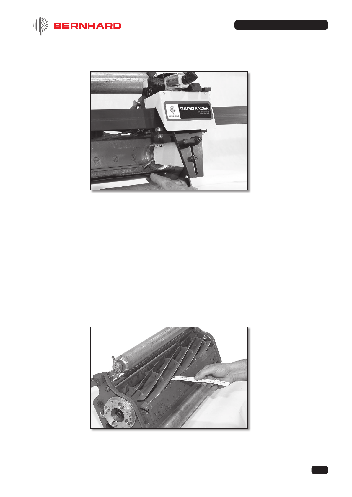
4.3.1 Two reel guide pins are attached
to the grinder carriage. These
allow the disc to sharpen the
bedknife without damaging
the reel blades. When hand
traversing the grinding head the
reel pins rotate the reel blades
clear of the grinding disc.
4.3.2 Slide the carriage to the left until the grinding disc is over the left end of the bedknife. Turn
the left adjustment spindle to lower the disc until it just lightly touches the bedknife.
Slide the carriage to the right until the disc is over the right end of the bedknife. Turn the
right hand adjustment spindle to lower the disc until it just lightly touches the bedknife.
Traverse the carriage along the rail and observe:
a) that the disc rubs lightly all along the top edge of the bedknife.
b) that the reel pins rotate the reel blade clear of the disc.
c) HYDRAULIC DRIVES
When grinding with the mower fully assembled it may be necessary to back o the reel,
if the reel pins are unable to turn the reel against the hydraulic pressure.

9
© Bernhard and Company Limited
RAPID FACER MANUAL
5.1 Wear safety goggles.
5.2.1 Attach the air line and turn on the air.
5.2.2 Position the grinding disc at the left end of the bedknife.
5.2.3 Start the air motor by depressing the throttle button. Hand traverse the carriage back and
forward along the rail to the right and the left.
Light sparking all along shows that the grinder disc is set correctly to cut parallel to the
bedknife.
Witness marks on the front face demonstrate whether the disc is set to grind the correct
clearance angle. The adjustable lever (part 15) allows the angle to be changed.
5. Operation
10
© Bernhard and Company Limited
RAPID FACER MANUAL
5.2.4 To increase the cut rotate the eccentric adjustment lever (item 10) on each magnet
assembly by a few degrees clockwise.
5.2.5 If the grinding disc is not in contact with the front face everywhere, a further movement of
the lever will be necessary. Finish o with a light cut.
5.2.6 NOTE: Regularly maintained blades will need very few cuts. Damaged blades will need
more.
5.2.7 Turn o the air and disconnect the air line.
5.2.8 Check that the ground nish on the bedknife edge is satisfactory.
5.2.9 Remove the Rapid Facer from the bedknife.
5.2.10 Rotate the reel and check that the cutting clearance is correct all along the full length of
each blade.
NOTE: Set the reel to cut paper at between .002" and .004" (.05mm-.1mm) clearance.
For best results trap one Bernhard Cutting Strip between reel and bedknife.

11
© Bernhard and Company Limited
RAPID FACER MANUAL
6. Maintenance
6.1 Cleanliness is important for correct operation and long life.
After each operation wipe all dust and abrasive materials from the slide rail and bearings.
Occasionally the feed slide face will need cleaning.
6.2 The air motor and gear box should be oiled each day of use and prior to being stored
away.
6.3 The machine relies on the disc holder rubber to maintain a steady pressure for the grinding
cut. If it is cracked or weakened it should be replaced.
7. Repairs
7.1 All components are readily available from your distributor.
In case of diculty do not hesitate to call us Toll free 1-888 GRIND IT (1-888 474 6348).
7.2 A perfectly straight slide is crucial to the successful operation of this machine. A bent or
damaged rail must be replaced.
7.3 Worn pillars and bearings are easily replaced.
7.4 The angle grinder is not prone to problems but if in diculty call our technical helpline.

12
© Bernhard and Company Limited
RAPID FACER MANUAL
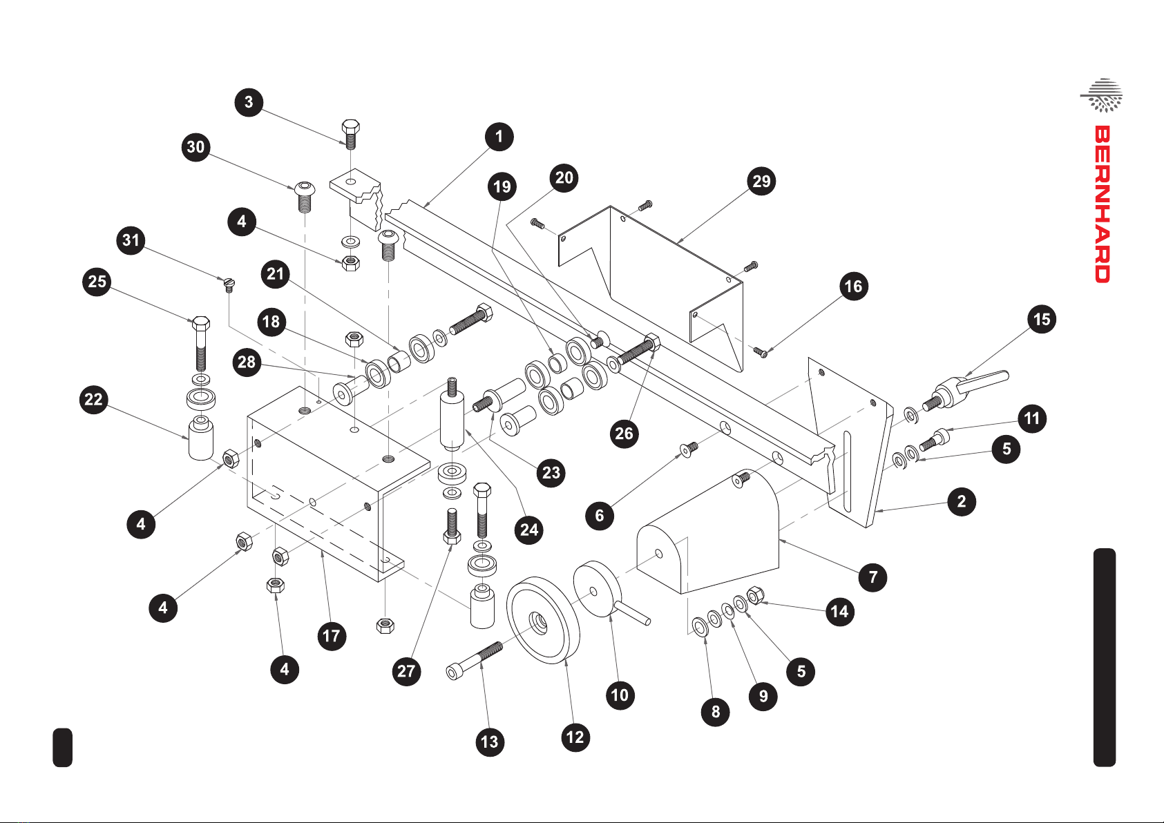
8. Parts List
Ref # Name of Part Qty. Old Part # New Part #
Rail Assembly
1 Rail...........................................................................................1 RF1501 A3000
2 Front Plate ............................................................................... 2 RF1502 A4057
3 M6 x 12 Hex Hd Bolt................................................................2 RF1503 A5718
4 M6 Nut ..................................................................................... 2 RF1504 A5516
5 M6 Washer ..............................................................................2 RF1505 A5320
6 M5 x 10 Csk Bolt......................................................................4 RF1506 A5130
Support Bracket Assembly
5 M6 Washer ............................................................................10 RF1505 A5320
7 Support Brkt (casting).............................................................. 2 RF1510 A4135
8 M8 Washer ..............................................................................2 RF1511 A5321
9 Belleville Spring ....................................................................... 2 RF1506 A5307
10 Eccentric Disc + Lever.............................................................2 RF1515 A9033
11 M6 x 10 x 5 Shoulder Screw.................................................... 2 A5144
12 Magnet.....................................................................................2 RF1512 A6754
13 M6 x 40 Cap Screw .................................................................2 RF1513 A5154
14 M6 Nylock Nut ......................................................................... 4 RF1514 A5517
15 Adjustable Kip Lever ...............................................................2 RF1519 A6124
Saddle Assembly
4 M6 Nut ..................................................................................... 6 RF1504 A5516
5 M6 Washer ..............................................................................7 RF1505 A5320
16 No 4 Self Tap Screw ................................................................4 RF1518 A5418
17 Saddle...................................................................................... 1 RF1530 A4118
18 Bearing ....................................................................................9 RF1536 A7708
19 Horiz. Pillar Spacer (short).......................................................1 RF1601 A9022
20 M6 x 8 C/sunk Screw............................................................... 1 RF1571 A5159
21 Horiz. Pillar Spacer (long)........................................................ 2 RF1600 A3011
22 Vertical Pillar ............................................................................2 RF1534 A9021
23 Horizontal Eccentric.................................................................1 RF1533 A9020
24 Vertical Eccentric .....................................................................1 RF1535 A9124
25 Hex. Head Bolt M6 x 40........................................................... 2 RF1573 A5722
26 Hex. Head Bolt M6 x 35........................................................... 2 RF1572 A5721
27 Hex. Head Bolt M6 x 12........................................................... 1 RF1503 A5718
28 Horizontal Pillar........................................................................2 RF1532 A9123
29 Saddle Guard (Name Plate) .................................................... 1 RF1537 A6610
30 (only on Rapid Relief unit)
Grinder Head Assembly
5 M6 Washer ..............................................................................1 RF1505 A5320
8 M8 Washer ..............................................................................1 RF1511 A5321
35 Wing Knob (M6).......................................................................2 RF1552 A6128
36 Wing Knob (M8) ......................................................................2 RF1553 A6132
37 Angle Bracket .......................................................................... 1 RF1554 A4019
38 Tool Support............................................................................. 1 RF1550 A4140
39 Reel Pin ................................................................................... 2 RF1551 A3036
40 Angle Grinder...........................................................................1 RF1560 A6749
41 Disc Holder .............................................................................. 1 RF1561 A3021
42 60 grit Disc Pack....................................................................25 RF1010 A6503
35 grit Disc Pack.................................................................... 25 RF1011 A6502
43 Grip Washer............................................................................. 1 RF1556 A5308
47 1/4 BSP x 6mm Elbow............................................................. 1 RF1566 A6708
48 1/4 BSP x 6mm Stud ...............................................................1 RF1567 A6709
49 6mm Poly-Nylon Hose............................................................. 1 RF1568 A6703

13
© Bernhard and Company Limited
RAPID FACER MANUAL
Reference Diagram • Rapid Facer Grinder Head Assembly
Grinder Head Assembly
Ref # Name of Part Qty. Old Part # New Part
5 M6 Washer 1 RF1505 A5320
8 M8 Washer 1 RF1511 A5321
35 Wing Knob (M6) 2 RF1552 A6128
36 Wing Knob (M8) 2 RF1553 A6132
37 Angle Bracket 1 RF1554 A4019
38 Tool Support 1 RF1550 A4140
39 Reel Pin 2 RF1551 A3036
40 Angle Grinder 1 RF1560 A6749
41 Disc Holder 1 RF1561 A3021
42 60 grit Disc Pack 25 RF1010 A6503
35 grit Disc Pack 25 RF1011 A6502
43 Grip Washer 1 RF1556 A5308
47 1/4 BSP x 6mm Elbow 1 RF1566 A6708
48 1/4 BSP x 6mm Stud 1 RF1567 A6709
49 6mm Poly-Nylon Hose 1 RF1568 A6703
14
© Bernhard and Company Limited
RAPID FACER MANUAL
Reference Diagram • Rapid Facer Assmebly

BERNHARD AND COMPANY LIMITED
Bilton Road • Rugby • England • CV22 7DT
Tel +44 1788 811600 • Fax +44 1788 812640
Email: [email protected]
USA Toll Free 1-888 GRIND IT (1-888 474 6348)
If you have any service or operational issues please contact your distributor
or phone our technical support hotline
Technical Helpline (USA only) 1-888 474 6348
Rest of World: UK Head Oce, England (+44) 1788 811600
Email: support@bernhard.co.uk
Technical FAQs can be found on our web site: www.bernhard.co.uk
When ordering spare parts please quote the machine type and serial number.
THE MANUFACTURERS ACCEPT NO RESPONSIBILITY FOR ANY SITUATION ARISING FROM
THE FITTING AND/OR USE OF NON-ORIGINAL SPARE PARTS.
This manual suits for next models
1
Table of contents


