TorcUP SR Series User manual

1
OPERATION AND MAINTENANCE
MODELS SR-500, SR-1000, SR-2000, SR-3000 AND SR-6000
MANUAL
SR SERIES
Electric Torque Wrenches
SR Series
Phone: +1 610-250-5800
Fax: +1 610-250-2700
Toll Free: 1-888-TORCUP-1
Email: [email protected]
Website: www.torcup.com
1025 Conroy Place, Easton, PA. 18040 U.S.A.

2
Operational and Maintenance Manual for TorcUP
SR-500, SR-1000, SR-2000, SR-3000 & SR-6000
Electric Torque Wrenches
Version 2: 2017 January
The Stryk tools contain alloy components which may
cause a hazard in certain explosive environments.
General Description of TorcUP Stryk Series Electric Torque Wrenches
The Stryk Series Electric Torque Wrench provides torque settings of up to
6,000 Ft. Lbs in clockwise and counter clockwise rotation, and its’ free joint execution allows
for random positioning of the tool.
Torque can be adjusted by regulating the amount of airow to the torque wrench and by
manipulating the air pressure regulating valve. An airow volume control is incorporated on
the top of the machine providing an extended torque range. The accuracy of maintaining
a selected torque is subject to the stability of your air supply. An airow of 40 to 55 CFMs
guarantees optimum performance even within a
non-protected working environment.
NOTICE
Series SR-500, SR-1000, SR-2000, SR-3000 and SR-6000 Electric Torque Wrenches are designed
for installing and removing threaded fasteners requiring precise high torque during bolt makeup and
maximum torque during bolt breakout.
TorcUP Inc. is not responsible for customer modication of tools for applications on
which TorcUP Inc. was not consulted.
WARNING
IMPORTANT SAFETY INFORMATION ENCLOSED.
READ THIS MANUAL BEFORE OPERATING TOOL.
IT IS THE RESPONSIBILITY OF THE EMPLOYER TO PLACE THE INFORMATION IN THIS
MANUAL INTO THE HANDS OF THE OPERATOR.
FAILURE TO OBSERVE THE FOLLOWING WARNINGS COULD RESULT IN INJURY.
The use of other than genuine TorcUPreplacement parts may result in safety
hazards, decreased tool performance, increased maintenance, and may invalidate
all warranties. Repairs should be made only by authorized personnel. Consult
your nearest TorcUPAuthorized Service Center.
Refer All Communications to the Nearest TorcUP Ofce or Distributor.
For Technical Support & Information Contact:
TorcUP Inc.
1025 Conroy Place, Easton, PA 18040 USA
Phone: +1 610-250-5800 Fax:+1 610-250-2700
email: [email protected]

3
INTRODUCTION & TABLE OF CONTENTS
Thank you for your purchase of a STRYK Torque Wrench and Controller from TorcUP, Inc.
The purpose of this manual is provide the user of the STRYK with a guide to understand the features
and functions of the controller.
For additional service and support, please contact your TorcUP represenative or TorcUP, Inc. at
TABLE OF CONTENTS
Warnings
Safety Information
Stryk and Control Box Diagram Overview

4
USING THE TOOL
• Keep hands, loose clothing & long hair away from the reaction arm and working area during
operation.
• This tool will exert a strong reaction force. Use proper mechanical support and correct
reaction arm positioning to control these forces. Do not position the reaction arm so that it
tilts the tool off the axis of the bolt, and never use the swivel inlets as a reaction stop.
• Avoid sharp bends and kinks that will cause severe back-up pressure in hoses and lead to
premature hose failure.
• Use accessories recommended by TorcUP.
• Use only impact sockets and accessories. Do not use hand (chrome) sockets or accessories.
• Use only sockets and accessories that correctly t the bolt or nut and function without tilting
the tool off the axis of the bolt.
• This tool is not insulated against electric shock.
• This equipment must not be operated or serviced unless the operator read the operating
instructions and fully understands the purpose, consequences and procedure of each step.
FAILURE TO OBSERVE THE FOLLOWING WARNINGS COULD RESULT IN INJURY
Do NOT Exceed Maximum Pressure. See Torque Chart with Tool. Damage May Occur.
Always wear ear
protection
when operating
this tool.
Do not carry
the tool
by the hose.
Keep body stance
balanced and rm.
Do not overreach
when operating
this tool.
The Reaction Arm must be
positioned against a positive stop.
Do not use the arm as a dead
handle. Take precautions to
make certain the operator’s hand
cannot be pinched between
the arm and a solid object.
Do not use damaged,
frayed or deteriorated
hydraulic hoses
and ttings.
Always wear eye
protection
when operating or
performing
maintenance
on this tool.
WARNING
Depending on the working environment your local health and safety regulations may require
you wear protective gear (i.e. safety shoes, hard hat, gloves, coveralls, etc.). In case external
forces are exerted on the equipment, non-compliance with these regulations may result in
injury. EAR PROTECTION MUST BE WORN WHEN OPERATING THIS TOOL.

5
SAFETY INFORMATION
OPERATIONAL SAFETY
1. Inspect, maintain, operate and install the tool in accordance with all applicable standards and
regulations (local, state, country, federal, etc.)
2. Do not remove any labels. Replace any damaged labels immediately.
3. Always use clean, dry air. Exceeding the maximum PSI recommended for the tool and noted
calibration chart may result in tool damage and/or hazardous situations including excessive
speed, rupture, or incorrect output torque or force.
4. Be sure all hoses and ttings are the correct size and tightly secured.
5. Ensure an accessible emergency shut off valve has been installed in the air supply line, and
make others aware of its location.
6. To prevent hose whipping if a hose fails or coupling disconnects, install a properly sized safety
air fuse upstream of hose and use an anti-whip device across any hose coupling without
internal shut-off.
7. Do not use damaged, frayed or deteriorated air hoses and ttings. Do not paint hoses.
8. Keep clear of whipping air hoses. Shut off the air compressor before approaching a whipping
hose.
9. Always turn off the air supply, bleed the air pressure and disconnect the air supply hose
before installing, removing or adjusting any accessory on this tool, or before performing any
maintenance on this tool or any accessory.
10. Do not lubricate tools with ammable or volatile liquids such as kerosene, diesel or jet fuel.
Use only TorcUP recommended lubricants.
11. Use only proper cleaning solvents to clean parts. Use only cleaning solvents which meet
current safety and health standards. Use cleaning solvents in a well ventilated area.
12. Keep work area clean, uncluttered, ventilated and illuminated.
PERSONAL SAFETY
1. When wearing gloves always be sure that the gloves will not prevent the throttle mechanism
from being released.
2. Always wear eye protection when operating or performing maintenance on this tool.
3. Always wear hearing protection when operating this tool.
4. Always use Personal Protective Equipment appropriate to the tool used and material worked.
This may include dust mask or other breathing apparatus, safety glasses, ear plugs, gloves,
apron, safety shoes, hard hat and other equipment.
5. Prevent exposure to and breathing of harmful dust and particles created by the tool use.
a. Some dust may be created by power sanding, sawing, grinding or other reproductive harm.
Some examples of these chemicals are:
i. Lead from based paints
ii. Crystalline silica from bricks and cement and other masonry products
iii. Arsenic and chromium from chemically treated lumber
Your risk from these exposures varies, depending on how often you do this type of work.
To reduce your exposure to these chemicals: work in a well ventilated area, and work with
approved safety equipment, such as dust masks that are specially designed to lter out
microscopic particles.
6. Keep others at a safe distance from your work area, or ensure they use appropriate personal
protective equipment.

6
SAFETY INFORMATION
7. Be aware of buried, hidden or other hazards in your work environment. Do not contact or
damage cords conduits, pipes, or hoses that may contain electrical wires, explosive gases or
harmful liquids.
8. Keep heands, loose clothing, long hair and jewelry away from working end of the tool.
9. Power tools can vibrate in use. Vibration, repetitve motions or uncomfortable positions may
be harmful to your hands and arms. Stop using any tool if discomfort, tingling feeling or pain
occurs. Seek medical advice before resuming.
10. Keep your body stance balanced and rm. Do no overreach when operating this tool.
Anticipate and be alert for sudden changes in motion, reaction torques, or forces during start
up and operation.
11. DO NO USE THE TOOL WHEN TIRED, UNDER THE INFLUENCE OR MEDICATION,
DRUGS OR ALCOHOL.
12. Never use a damaged or malfuncting tool or accessory.
13. Do not modify the tools, safety devices or accessories.
14. Do not sue this tool for purposes other than those recommended.
15. Never exceed rated RPM of tool.

7
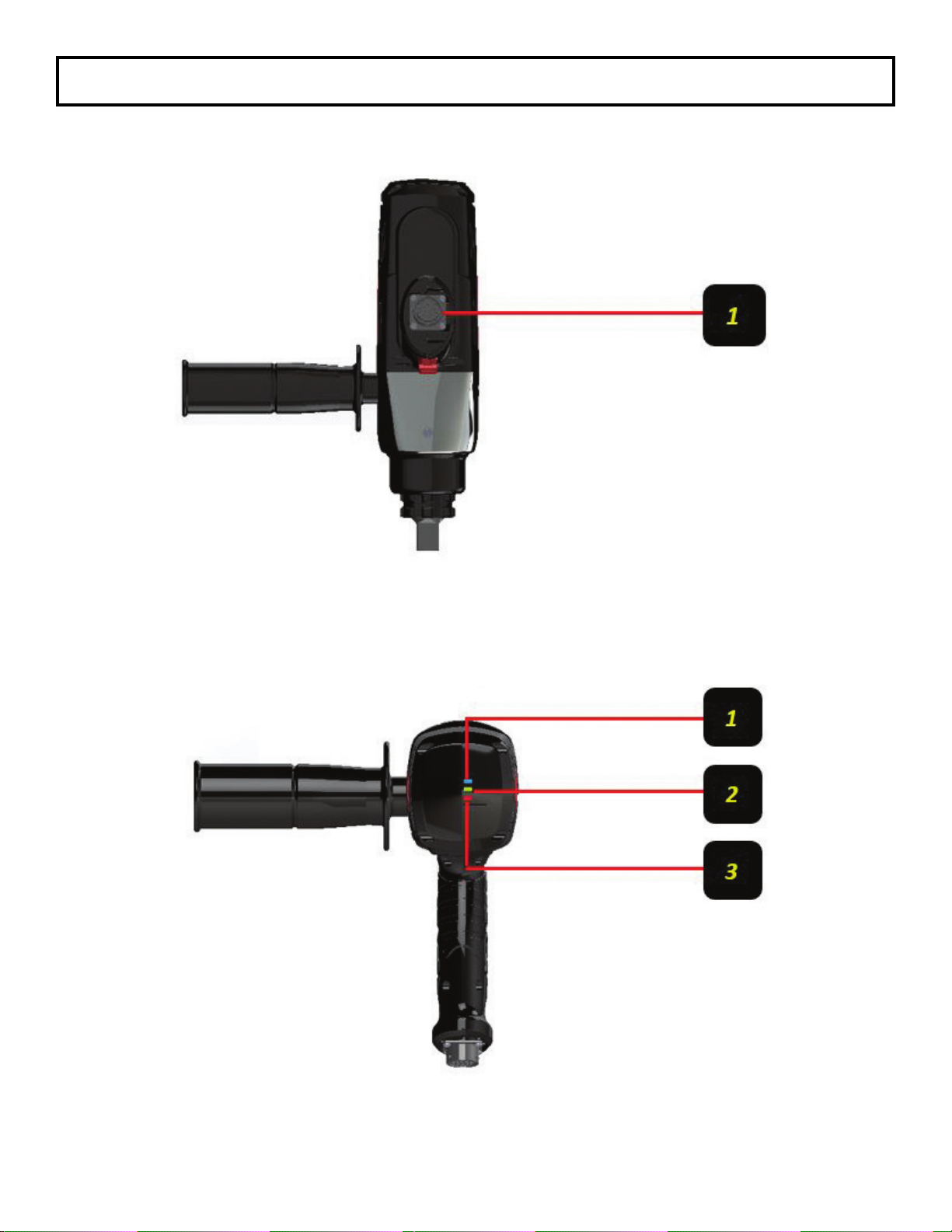
STRYK AND CONTROL BOX OVERVIEW
STRYK FRONT PANEL
FIGURE 1
STRYK CABLE CONNECTIONS
FIGURE 2
1- Tool Connector (19 Pin) -- Standard connection point for tool cable. Match
yellow cable end to the controller box.
2- Power Cord Connection (3 Pin) -- Standard power connection point
1- System Main Power Switch (Illuminated)
2- Servo Drive Reset Switch
3- Universal Serial Bus (USB) -- Data Retrieval / Software Updates
4- Emergency Stop Button (Push to Engage / Pull to Disengage
5- 7.5” Touch Screen HMI
8
STRYK AND CONTROL BOX OVERVIEW
STRYK TOOL CONNECTIONS
FIGURE 3
STRYK TOOL LED INDICATOR
FIGURE 4
1- Tool Power Indicator (Blue) -- Light on constantly while tool is on
2- Pass Indicator Light (Green)
3- Fail Indicator Light (Red)
1- Tool Connector (19 Pin) -- Standard connection point for tool cable

9
1. Ensure air line is not connected to tool before performing the following steps.
2. Ensure the reaction arm is properly attached and secured to splined section on the torque tool.
3. Select your desired square drive size and bolt/nut AF size impact socket or hex-drive socket for
use.
4. Secure impact socket on tool square drive with a safety pin and secure a safety o-ring on the
socket.
5. Use a quality Filter/Lubricator/Regulator Unit that meets airow requirements or use TorcUP
RAPTOR F/R/L Unit.
6. Ensure F/R/L has proper pneumatic oil for lubrication. See requirements for oil specications
sheet.
7. See illustration below for details:
IMPORTANT
For long life of the air motor:
Use a quality F/R/L Unit
Must meet airow requirements
Lubricator provides oil to air motor
Filter separates water to extend life
to motor vanes
Regulator allows accurate
setting of output
1.
1.
1.
2. 2.
2.
3.
Slide Rubber Safety Ring
Over Safety Pin Safety Pin Safety Screw
PLACING THE TOOL IN SERVICE

10
1. Torque depends on the air pressure exerted on the air motor under load. Adjusting the F/R/L Unit
Regulator Knob initially sets torque. To decrease torque output turn the regulator counter-
clockwise to lower air ow/pressure. All Raptors are shipped calibrated per TorcUP Procedures.
2. Check for desired torque setting for your selected model on the supplied torque chart. On the
RAPTOR F/R/L, adjust air pressure by using the air regulator knob for desired pressure/torque.
With the RAPTOR Series Torque Wrench under load (not on the nut/bolt), press the toggle switch.
Once pressure is set for desired torque output and airow/pressure, push in on regulator knob to
lock unit. While the RAPTOR Series Torque Wrench is under load, running at free speed (not
on the nut/bolt), adjust the RAPTOR F/R/L pressure at the same time.
A. SETTING TORQUE FOR BOLT TIGHTENING
1. Establish the air pressure required using the Torque Calibrated Chart, provided with the tool.
2. Push trigger using tightening direction per A on below diagram.
3. Adjust the regulator until the correct pressure is shown on the gauge by turning adjustment
knob clockwise.
B. SETTING TORQUE FOR BOLT LOOSENING
1. Establish the air pressure required using the Torque Calibrated Chart, provided with the tool.
2. Push Trigger using loosening Direction per B on below diagram.
3. Set the air pressure the same as with tightening.
OPERATING PROCEDURE

11
After extended use of the RAPTOR Series Torque Wrench, the air pressure setting should be
re-checked and may require minor adjustment. This is usually caused by variations in your air
supply unit providing airow to the F/R/L Unit or due to weather conditions.
Within the very rst few hours of operation a slight amount of grease may leak through the
equipment casing. In this case remove excess to avoid risk of slipping while running the
equipment or – for some specic applications – environmental pollution.
In the case of degrading performance or other apparent damage, immediately send your
RAPTOR Series Torque Wrench to TorcUP, Inc or contact your Local Representative or
Distributor. Unit must be properly packaged for shipping.
OPERATING PROCEDURES
Unauthorized manipulation of air motor, valves, & TorcUP F/R/L Unit or tampering with
either will result in loss of warranty! Also for the life of your TorcUP RAPTOR Series
Torque Wrench air supply should be clean and free of particles, water and other remains.
Pollution of hose couplings or aggressive substances reaching air motor via the supply
hose may cause damage to air motor vanes. Use approved F/R/L Units to obtained oil-
enriched and ltered supply. Non-compliance with the specied operating air pressure will
result in higher wear of the motor. Degradation in performance is likely to result. Also for
extreme cold weather use approved cold weather pneumatic lubrication to prevent freeze
ups.
Beware of low-pressure air components. Do not fold or bend the supply hose excessively and
check the hose for damage before use. A damaged hose must not be used, as there is a risk of
a hose burst. This may lead to a wildly lashing hose with a risk of personal injury. Also, check the
air tting and connections for tightness or damage.
OPERATING PROCEDURE
NOTICE
WARNING
IMPORTANT
WARNING

12
TIGHTENING AND LOOSENING OF BOLTS OR NUTS
TIGHTENING AND LOOSENING OF BOLTS OR NUTS
• Beware of non-xed freely rotating reaction arms or of rotating impact sockets.
• Loose clothes, long hair, cables, etc. are always to be kept away from danger/rotation area.
When the machine is put into operation, it is mandatory to wear ear protection, safety shoes
and safety goggles.
• Never leave a running RAPTOR Series Torque Wrench unattended and always be ready to
switch off the machine if necessary. Maintain a safety distance of arm length.
• Always place the impact socket or hex driver snugly on screw or nut/bolt. Faulty screw or nut/
bolt connections may result in exceeding the mechanical stress limit of the material, causing it
to break. Parts splintering off may cause bruises or even life-threatening injuries.
• Due to emission of an air-oil mixture, a breathing mask must be worn, especially when work-
ing over the head and in tight, secluded spaces.
When torquing and untorquing fasteners, always hold/position the RAPTOR Series Torque Wrench in
line with the fastener axis to avoid damage to the application. See Firgure 1 on the following page.
The indicated calibrated torque settings have to be considered only as a guideline. Because of
variations in pressure and/or air ow, as well as other application issues, deviations from the
calibration certicate may be necessary. Due to the CFM required, when the tool is running at free
speed, it may not be possible to set the regulator to the desired pressure due to air pressure drop off.
The CFM requirement is lower once the tool is under load, so if this happens, set the regulator to the
desired PSI without the tool running. Try tightening down the fastener and check the PSI when the
tool stalls. If the tool stalls at the PSI setting, the desired torque has been reached. If it has stalled
before, try adjusting regulator higher until the correct stall PSI is reached.
WARNING
NOTICE

13
1. Place your RAPTOR Series Torque Wrench
completely over and on the fastener to be tightened or
loosened. (4)
2. Ensure the reaction area / movement is taken up
by the Reaction Arm (5). Also, the ensure reaction is
stable and will support counter torque.
3. Hold RAPTOR Series Torque Wrench
perpendicular to the fastener axis (6) for the complete
duration of the rotation process for tightening or
loosening.
4. After activating the toggle switch (3) on the pistol
grip, when tightening the fastener the Tool will rotate
until it becomes torqued and the RAPTOR Series
Torque Wrench will then stall out.
5. The toggle will then need to be depressed in the
opposite direction for opposite tool rotation to release
counter torque load off the reaction arm. Once this
done, you then can remove and move to your next
fastener.
6. For loosening a fastener, the unit will continue to
rotate until the fastener is removed or when fastener
is loose by hand you can stop move to next fastener.
7. Continue the process for tightening or loosening
for each fastener you require.
8. If torque requirements require your application
to go in torque increments, then set RAPTOR
Series Torque Wrench to your rst torque requirement. Tighten fastener as per your required
tightening bolt sequence. Then reset for next settings on F/R/L unit by adjusting regulating
knob as described earlier.
9. Your personnel can be trained by your TorcUP Representative or Distributor on use of this
product if so desired.
4
Because of the high mechanical stress on the RAPTOR Series air motor it is essential to provide
the F/R/L Unit with sufcient oil supply. Non-compliance bears risk of damaging the vanes of
the air motor. Enriching the supply by adjusting the oil feed on F/R/L to 2 to 3 drops per minute
will sufce for heavy continuous equipment use.
1. Remove the RAPTOR Series Torque Wrench from work while depressing toggle switch and back off
the regulator knob to decrease the pressure to zero.
2. Disconnect the air hose to the RAPTOR Series Torque Wrench.
3. Remove and change the socket or accessory adaptor for next project. Ensure the socket or accessory
is properly secured to the square drive with a locking pin and safety securing o-ring.
CHANGING ACCESSORIES
TIGHTENING AND LOOSENING OF BOLTS OR NUTS
14
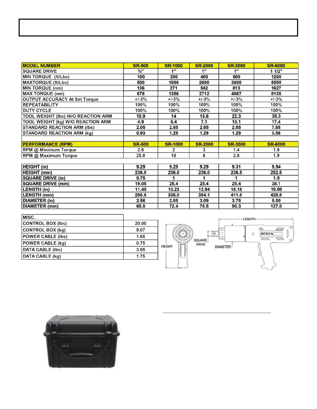
TECHNICAL SPECIFICATIONS
Controller Box Dimensions (L x W x H):
Imperial (in): 14.9” x 12.13” x 9.58”
Metric (mm): 387.5 x 308.1 x 243.3

15
NOISE AND VIBRATIONS
Sound pressure level, measured in accordance OSHA & German Machinery-Noise-Information-
Leaet-3-GSGV requirements dated 18 Jan 1991, §1, (1 e) at maximum equipment performance
is just over 85 dB(A).
In accordance with §1, (2) of the same leaet sound pressure levels were measured for different
work cycles, with the sensor at a distance of 1 meter to the geometric center of the machine.
Vibrations become moderate just prior reaching the pre-set torque value.
On request RAPTOR Series Pneumatic Torque Wrenches with lower sound pressure levels (<85
dB(A)) are available as special modication. Because this modication comprises a sound
absorber, relevant torque values may change on given unit.
Beware of components under pressure. Inadvertent activation of the torque wrench may lead to
both a risk of injury as well as damage to property. When detaching the supply air hose always
shut off air to supply rst. Non-compliance with procedure may result in an out-of –control
supply hose thus risking injury personal injury and damage to property.
STORING YOUR RAPTOR SERIES TORQUE WRENCH
1. Shut off pressurized air to the F/R/L by turning off the air to the F/R/L Unit.
2. Bleed off the air by depressing toggle switch in either direction on the Pistol Grip.
3. Disconnect the supply hose from the F/R/L Unit and disconnect the air hose at the RAPTOR
Series Pneumatic Torque Wrench.
4. If the RAPTOR Series Torque Wrench is not to be used for an extended period of time,
spray pneumatic lubricating oil into the RAPTOR Series Fitting. Reconnect air hose and
supply hose to the F/R/L Unit air inlet tting. Cycle the F/R/L unit momentarily to ensure that
2-3 drops of lubricating oil has entered into the air motor. Then stop and shut-off the
system as previously mentioned above and store your RAPTOR Series Torque Wrench
in the case that it was shipped in.
TECHNICAL SPECIFICATIONS

16
STRYK CONTROL BOX MAIN DISPLAY FUNCTIONS
GETTING STARTED
1. Attach tool controller cable to control box. (See gure 2)
2. Attach tool controller cable to Stryk Wrench. (See Figure 3)
3. Attach power cord to control box. (See Figure 2)
4. Plug power cord into electrical receptacle.
5. Reset e-stop button by pulling up on the e-stop button.
6. Turn on power by switching the system power button to ON.
The controller box will system boot for
a few seconds. When the system is
nished booting, the screen (shown on
right) will be displayed.
MAIN DISPLAY FUNCTIONS
1. Select the STRYK TOOL MODEL by touching the down arrow to the right of the tool listing.
A drop down menu will appear. Select from the following STRYK tools in 115v and 230v
versions.
• STRYK 500
• STRYK 1000
• STRYK 2000
• STRYK 3000
• STRYK 6000
2. Enter the SERIAL NUMBER of your STRYK Tool. This serial number will be marked on the
tool and calibration certicates provided with the tool. A drop down keypad will appear. Enter
up to 8 characters for a serial number. Press ENTER when complete.
3. Enter the GAIN, NULL, & GAIN^2 by touching the eld to the right of each designator. A drop
down keypad will appear.
• Enter the GAIN value provided on the calibration documents. Press ENTER when
complete.
• Enter the NULL value provided on the calibration documents. Press ENTER when
complete.
• Enter the GAIN^2 value provided on the calibration documents. Press ENTER when
complete.
4. Touch the APPLY button when all of the information has been entered. This loads the
selected tool in top level memory
NOTE: The GAIN, NULL, & GAIN^2 values are unique to each STRYK tool. If improper
values are entered into the control box, inaccurate torque results will occur.
4
1
2
3

17
WORKING WITH MULTIPLE TOOLS
The STRYK controller box has the capability of storing multiple tool models and their corresponding
GAIN, NULL and GAIN^2 values. Only one (1) tool selection can be loaded into top level memory at
a time.
1. NEW – is used to enter a new tool. Touch the NEW button, and a new model number will
appear. This tool model can be changed to a name of your choice by touching eld tool
selection eld to the right and using the drop down keypad to enter desired tool name. Press
ENTER when complete.
a. Enter serial number, GAIN, NULL & GAIN^2 as detailed in “Tool Selection and
Setup” Section
2. SAVE – is used to permanently save new tool data or changes made to a tool model. By
pressing the SAVE button, the new tool model, name, and data are now saved for future use.
3. APPLY – this button is used to load selected tool into top level memory for operation.
4. DELETE – this button is used to permanently delete any tool loaded into top level memory.
This data cannot be recovered, but can be reentered manually by using NEW tool button.
5. NEXT – when pressed it will activate the units selection screen.
UNITS SELECTION
The UNITS screen currently offers two selections.At this time, the STRYK has the capability to
display in imperial and metric units.
1. Units Selection Button - enables the ability to toggle between English and Metric.
2. Units - displays in ft/lb or Nm.
3. Home Button - when pressed it will activate the home screen.
3
4
4
1
2
2
1
3

18
HOME SCREEN
The HOME Screen can be reached on various screens by touching the button. The HOME
screen greatly speeds up navigation throughout the program. The next few sections will detail each
area of the home screen.
TOOL AND UNIT SELECTION
By pressing the TOOL SELECTION button, the
screen to the right will appear. Operations for this
mode are found detailed in the “TOOL SELECTION
AND SETUP” Section.
By pressing the UNIT SELECTION button,
the screen to the right will appear. Operations
for this mode are found detailed in the “UNIT
SELECTION” Section.

19
RUN MODE
By pressing the RUN button from the HOME
screen, the “Select Run Mode” screen will appear.
This screen allows the selected STRYK tool to be operated in two different modes.
• ANGLE CONTROL – In this mode, a prevailing torque can be achieved and continuous
rotation of the nut for a desired angle of rotation can both be achieved.
• TORQUE CONTROL – This mode allows the user to operate the STRYK tool to desired
predetermined nal torque settings.
See the following sections for detailed operation instructions for both modes of operation.

20
ANGLE CONTROL
Press the ANGLE CONTROL button from the RUN screen, and the following screen will be displayed.
This screen is divided into two sections, the section to the right is the data input side and the section
to the left is the actual run data.
3
4
1
2
5
1. Set desired angle rotation for either “TIGHTEN”
or “LOOSEN”.
2. Set desired nut rotation for either “RIGHT HAND
THREADS” or “LEFT HAND THREADS”.
3. Enter desired angle of rotation by touching the
data eld next to the “Set Angle” heading. Use
the drop down keypad to enter your desired
degrees of rotation (See Figure 5).
4. Enter desired prevailing torque by touching the
data input eld. Use the drop down keypad to
enter the desired prevailing torque (See Figure
5).
5. Set desired tolerance for the PREVAILING
TORQUE, andANGLE OF ROTATION, by
touching the OVER TOLERANCE and UNDER
TOLERANCE elds and using the drop down
keypad to enter the percentage tolerance. The
minimum and maximum angles will be displayed.
This setting allows for a +/- setting to the torque
and rotation angle (See Figure 6).
Figure 5
Figure 6
Actual Tool Run Readout Data Input
This manual suits for next models
5
Table of contents
Other TorcUP Power Tools manuals

TorcUP
TorcUP ULTRA series Manual

TorcUP
TorcUP VT Series User manual

TorcUP
TorcUP TU Series User manual

TorcUP
TorcUP TXU-2 User manual

TorcUP
TorcUP VOLTA VT Series User manual

TorcUP
TorcUP TX Series User manual

TorcUP
TorcUP RP-500 User manual

TorcUP
TorcUP RAPTOR RP Series Setup guide

TorcUP
TorcUP TXU Series User manual

TorcUP
TorcUP TX LINK Series Operating manual


Popular Power Tools manuals by other brands


Campbell Hausfeld
Campbell Hausfeld AF010600 operating instructions

Mountz
Mountz K250 operating instructions

Ironton
Ironton 61478 owner's manual

Fairport
Fairport PP46 Operation, spare parts and service manual

ALFRA
ALFRA TMC 600R Operation manual

Electronica Technologies
Electronica Technologies EL700 manual