TorcUP VOLTA VT Series User manual

1
OPERATION AND MAINTENANCE
MODELS VT-500, VT-1000, VT-1000-1,VT-2000, VT-3000, AND VT-6000
MANUAL
VT Series
Phone: 1 610-250-5800
Fax: 1 610-250-2700
Toll Free: 888-TORCUP1
Email: SALES@TORCUP.COM
Website: WWW.TORCUP.COM
1025 Conroy Place, Easton, PA. 18040 U.S.A.
BATTERY-POWERED TORQUE WRENCHES

2
Operational and Maintenance Manual for TorcUP
VT-500, VT-1000-1, VT-1000, VT-2000, VT-3000 &
VT-6000
Battery-Powered Torque Wrenches
Version 3: 2023 JULY
The Volta tools contain alloy components which may
cause a hazard in certain explosive environments.
General Description of TorcUP VOLTA Series Battery-Powered Torque Wrenches
The VOLTA Series Battery-Powered Torque Wrench provides torque settings of up to
6,000 lbf-ft in clockwise rotation, and its free joint execution allows for random positioning of
the tool.
NOTICE
Series VT-500, VT-1000-1, VT-1000, VT-2000, VT-3000 and VT-6000 Battery-Powered Torque
Wrenches are designed for installing and removing threaded fasteners requiring precise high torque
during bolt makeup and maximum torque during bolt breakout.
TorcUP Inc. is not responsible for customer modication of tools or for applications on
which TorcUP Inc. was not consulted.
WARNING
IMPORTANT SAFETY INFORMATION ENCLOSED.
READ THIS MANUAL BEFORE OPERATING TOOL.
IT IS THE RESPONSIBILITY OF THE EMPLOYER TO PLACE THE INFORMATION IN THIS
MANUAL INTO THE HANDS OF THE OPERATOR.
FAILURE TO OBSERVE THE FOLLOWING WARNINGS COULD RESULT IN INJURY.
The use of other than genuine TorcUP replacement parts may result in safety
hazards, decreased tool performance, increased maintenance, and may invalidate
all warranties. Repairs should be made only by authorized personnel. Consult
your nearest TorcUP Authorized Service Center.
Refer All Communications to the Nearest TorcUP Ofce or Distributor.
For Technical Support & Information Contact:
TorcUP Inc.
1025 Conroy Place, Easton, PA 18040 USA
Phone: +1 610-250-5800 Fax:+1 610-250-2700
email: [email protected]

3
USING THE TOOL
• Keep hands, loose clothing and long hair away from the reaction arm and working area during
operation.
• This tool will exert a strong reaction force. Use proper mechanical support and correct
reaction arm positioning to control these forces. Do not position the reaction arm so that it
tilts the tool o the axis of the bolt, and never use the air inlet as a reaction stop.
• Use only accessories recommended by TorcUP.
• Use only impact sockets and accessories rated for approperiate torque output. Do not use
hand (chrome) sockets or accessories.
• Use only sockets and accessories that correctly t the bolt or nut and function without tilting
the tool o the axis of the bolt.
• This tool is not insulated against electric shock.
• This equipment must not be operated or serviced unless the operator reads the operating
instructions and fully understands the purpose, consequences and procedures of each step.
FAILURE TO OBSERVE THE FOLLOWING WARNINGS COULD RESULT IN INJURY
Always wear ear
protection
when operating
this tool.
Keep body stance
balanced and rm.
Do not overreach
when operating
this tool.
The Reaction Arm must be
positioned against a positive stop.
Do not use the arm as a dead
handle. Take precautions to
make certain the operator’s hand
cannot be pinched between
the arm and a solid object.
Always wear eye
protection
when operating or
performing
maintenance
on this tool.
WARNING
Depending on the working environment, your local health and safety regulations may require
you wear protective gear (i.e. safety shoes, hard hat, gloves, coveralls, etc.). In case external
forces are exerted on the equipment, non-compliance with these regulations may result in
injury. EAR PROTECTION MUST BE WORN WHEN OPERATING THIS TOOL.

4
SAFETY INFORMATION
OPERATIONAL SAFETY
1. Inspect, maintain, operate and install the tool in accordance with all applicable standards and
regulations (local, state, county, federal, etc.)
2. Do not remove any labels. Replace any damaged labels immediately.
3. Do not lubricate tools with ammable or volatile liquids such as kerosene, diesel or jet fuel.
Only use TorcUP recommended lubricants.
4. Only use proper cleaning solvents to clean parts. Use only cleaning solvents which meet
current safety and health standards. Use cleaning solvents in a well ventilated area.
5. Keep work area clean, uncluttered, ventilated and illuminated.
PERSONAL SAFETY
1. When wearing gloves, always be sure that the gloves will not prevent the throttle mechanism
from being released.
2. Always wear eye protection when operating or performing maintenance on this tool.
3. Always wear hearing protection when operating this tool.
4. Always use Personal Protective Equipment appropriate to the tool used and the material being
worked on. This may include dust mask or other breathing apparatus, safety glasses, ear
plugs, gloves, apron, safety shoes, hard hat and other equipment.
5. Avoid breathing in any exhaust from tool use.
a. Some dust may also be created by working in close proximity to the following chemicals:
i. Lead from lead-based paints
ii. Crystalline silica from bricks and cement and other masonry products
iii. Arsenic and chromium from chemically treated lumber
Your risk from these exposures varies depending on how often you do this type of work.
To reduce your exposure to these chemicals: work in a well ventilated area, and work with
approved safety equipment, such as dust masks that are specially designed to lter out
microscopic particles.
6. Keep others at a safe distance from your work area or ensure they use appropriate personal
protective equipment.
7. Be aware of buried, hidden or other hazards in your work environment. Do not contact or
damage cords conduits, pipes, or hoses that may contain electrical wires, explosive gases or
harmful liquids.
8. Keep hands, loose clothing, long hair and jewelry away from the working end of the tool.
9. Power tools can vibrate in use. Vibration, repetitve motions or uncomfortable positions may
be harmful to your hands and arms. Stop using any tool if discomfort, tingling feeling or pain
occurs. Seek medical advice before resuming.
10. Keep your body stance balanced and rm. Do no overreach when operating this tool.
Anticipate and be alert for sudden changes in motion, reaction torques, or forces during start
up and operation.
11. DO NO USE THE TOOL WHEN TIRED OR WHEN UNDER THE INFLUENCE OF
MEDICATION, DRUGS OR ALCOHOL.
12. Never use a damaged or malfunctioning tool or accessory.
13. Do not modify the tools, safety devices or accessories.
14. Do not use this tool for purposes other than those recommended.
5
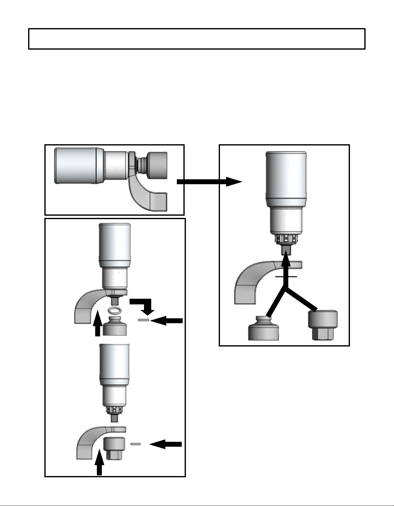
PLACING THE TOOL IN SERVICE
1. Ensure the reaction arm is properly attached and secured to the splined section of the torque tool.
2. Select your desired square drive size and bolt/nut AF size impact socket or hex-drive socket for use.
3. Secure impact socket onto the tool square drive with a safety pin and secure a safety o-ring on the
socket.
4. See illustration below for details:
1.
1.
1.
2. 2.
2.
3.
Slide Rubber Safety Ring
Over Safety Pin Safety Pin Safety Screw
PLACING THE TOOL IN SERVICE

6
SETTING THE TORQUE
1. Momentarily press Volta trigger to activate LCD display (the board will remain illuminated for
approximately 30 seconds after the trigger is released).
2. Use the two arrows to set desired torque. Pressing the arrow pointed upward will raise the
torque and pressing the arrow pointed downward will lower the torque (pressing and holding a
button will cycle through the torque settings).
3. Simultaneously pressing the up and down arrows will switch the display torque between lbf-ft
and Nm (NOTE: TRANSITIONING UNITS AUTOMATICALLY RESETS THE TORQUE TO THE
LOWEST POSSIBLE VALUE).
4. After the LCD times out, pull the trigger to reactivate it, the torque setting will remain set until
changed.
TORQUE THROUGH THE LIFE OF THE BATTERY
If the tool is used continuously/rapidly to the point that the tool feels hot to the touch, the tool
accuracy can diminish and cause a slight increase in torque. Once the tool cools down, the
accuracy should return to normal.
The battery is recommended to be changed before the charge gets to 25% battery life,
although the torque should be consistent until the last few fastenings before the battery dies.
NOTE: This tool is designed to be operated with right-hand thread fasteners. There is a 15%
reverse bias to assist with breakout. If this tool is to be used with left-hand thread fasteners
consult TorcUP.
OPERATING PROCEDURES

7
After extended use of the VOLTA Series Torque Wrench, in the case of degrading performance
or other apparent damage, immediately send your VOLTA Series Torque Wrench to TorcUP,
Inc or contact your Local Representative or Distributor. The unit must be properly packaged for
shipping.
OPERATING PROCEDURES
NOTICE
TIGHTENING AND LOOSENING OF BOLTS OR NUTS
TIGHTENING AND LOOSENING OF BOLTS OR NUTS
• Beware of non-xed, freely rotating reaction arms or of rotating impact sockets.
• Loose clothes, long hair, cables, etc. are always to be kept away from the danger/rotation
area. When the machine is put into operation, it is mandatory to wear ear protection, safety
shoes and safety goggles.
• Maintain a safe distance from all reaction points.
• Always place the impact socket or hex driver snugly onto the screw or nut/bolt. Faulty screw
or nut/bolt connections may result in exceeding the mechanical stress limit of the material,
causing it to break. Parts that splinter o may cause bruises or even life-threatening injuries.
When tightening and loosening fasteners, always hold/position the VOLTA Series Torque Wrench in
line with the fastener axis to avoid damage to the application. See Figure 1 on the following page.
WARNING

8
1. Remove the VOLTA Series Torque Wrench from the application.
2. Disconnect the battery to the VOLTA Series Torque Wrench.
3. Remove and change the socket or accessory adaptor for the next project. Ensure the socket
or accessory is properly secured to the square drive with a locking pin and safety securing
o-ring.
CHANGING ACCESSORIES
TIGHTENING AND LOOSENING OF BOLTS OR NUTS
Fig. 1
1. Place your VOLTA Series Torque Wrench
completely over and on the fastener to be
tightened or loosened.
2. Ensure the reaction area / movement is taken
up by the Reaction Arm. Also, ensure the
reaction is stable and will support counter
torque.
3. Hold the VOLTA Series Torque Wrench
perpendicular to the fastener axis for
the complete duration of the rotation process for
tightening or loosening.
4. Ensure the direction switch is set to tighten.
Then, press the trigger on the pistol grip to
tighten the fastener. The tool will rotate
until the fastener becomes torqued, and the
VOLTA Series Torque Wrench will then stop/beep.
5. For loosening a fastener, place the direction
switch in reverse. Then, press the trigger on
the pistol grip to loosen the fastener.
The unit will continue to rotate until the fastener is removed OR once the fastener is loose it
can be removed by hand and you can move on to the next fastener.
6. Continue the process for tightening or loosening for each fastener you require.
7. If torque requirements necessitate the use of torque increments, set the VOLTA Series Torque
Wrench to your rst torque requirement. Tighten fastener as per your required tightening bolt
sequence. Then, reset for the next setting(s).
8. Your personnel can be trained by your TorcUP Representative or Distributor on use of this
product if so desired.

9
1. Do not expose power tools to rain or wet conditions. Water entering a power tool will
increase the risk of electric shock and damage the tool.
2. Disconnect the battery pack from the power tool before changing accessories or
storing power tools. Such preventive safety measures reduce the risk of starting the
power tool accidentally.
3. Store idle power tools out of the reach of children and do not allow persons unfamiliar
with the power tool or these instructions to operate the power tool. Power tools are
dangerous in the hands of untrained users.
4. Maintain power tools. Check for misalignment or binding of moving parts, breakage of
parts and any other condition that may aect the power tool’s operation. If damaged,
have the power tool repaired before use. Many accidents are caused by poorly
maintained power tools.
5. Use the power tool, accessories and tool bits etc. in accordance with these
instructions, taking into account the working conditions and the work to be performed.
Use of the power tool for operations dierent from those intended could result in a
hazardous situation.
BATTERY SAFETY INSTRUCTIONS
BATTERY USE AND CARE
1. Recharge only with the charger specied by the manufacturer. A charger that is
suitable for one type of battery pack may create a risk of re when used with another
battery pack.
2. Use power tools only with specically designated battery packs. Use of any other
battery packs may create a risk of injury and re.
3. When battery pack is not in use, keep it away from other metal objects, like paper
clips, coins, keys, nails, screws or other small metal objects, that can make a
connection from one terminal to another. Shorting the battery terminals together may
cause burns or a re.
4. Under abusive conditions, liquid may be ejected from the battery; avoid contact. If
contact accidentally occurs, ush with water. If liquid contacts eyes, additionally seek
medical help. Liquid ejected from the battery may cause irritation or burns.
5. Protect battery packs from water and moisture.
6. Do not expose battery packs to open ame.
NOTICE
Note: Prior to use, please see pages 17-21 of this user manual to review the battery
product safety data sheet.

10
BATTERY TROUBLESHOOTING
If the VOLTA Series Torque Wrench switches o automatically, the electronics have
activated automatic protection mode. A warning signal sounds (continuous beeping). The
beeping stops after a maximum of 30 seconds or when the trigger is released. In spite
of this protective function, overloading is still possible with certain applications and can
result in damage to the tool.
Causes and Remedies:
1. Battery almost empty: The electronics protect the battery pack against damage
through total discharge). If one LED is ashing, the battery pack is almost depleted. If
necessary, press the button and check the LEDs to see the charge level. If the battery
pack is almost depleted, it must be recharged.
2. Long continuous overloading of the machine: This will activate the temperature cut-
out. Leave the tool or battery pack to cool. Note: If the battery pack feels very warm, the
pack will cool more quickly in an “AIR COOLED” charger. Note: The tool will cool more
quickly if you operate it at idling speed.
3. Safety Shutdown: The tool was SWITCHED OFF automatically. If the slew rate of the
current is too high (for example, if the tool suddenly seizes or kickback occurs), the tool
switches o. Switch o the tool at the trigger. Switch it on again and continue to work as
normal. Try to prevent the tool from seizing.
Note: The LED lamp switches o automatically after a specic time. To activate the
electronic functions, press the trigger.

11
TECHNICAL SPECIFICATIONS
Charger Requirements: 110 - 120 V (50-60 Hz) and 230 - 240 V (50-60 Hz)
MODEL NUMBER VOLTA
500
VOLTA
1000-1
VOLTA
1000
VOLTA
2000
VOLTA
3000
VOLTA
6000
SQUARE DRIVE 3/4” 3/4” 1” 1” 1” 1.5”
MIN. TORQUE (lbf-ft) 120 240 240 500 750 1200
MAX. TORQUE (lbf-ft) 500 1000 1000 2000 3000 6000
MIN. TORQUE (Nm) 160 330 330 680 1020 1630
MAX. TORQUE (Nm) 680 1360 1360 2710 4070 8130
HEIGHT A (w/ battery) (in) 10.57 10.54 10.54 10.54 10.76 11.38
HEIGHT A (w/ battery) (mm) 268.48 267.67 267.67 267.67 273.18 289.05
LENGTH B (in) 7.65 9.08 9.28 9.72 12.49 13.17
LENGTH B (mm) 194.28 230.73 235.59 246.84 317.14 334.42
DIAMETER C (in) 3.32 2.85 2.85 3.10 3.75 5.00
DIAMETER C (mm) 84.25 72.39 72.39 78.64 95.25 127
WEIGHT (w/o reaction arm & battery) (lbs) 6.6 9.15 9.6 11.2 17.7 33.5
WEIGHT (w/o reaction arm & battery) (kg) 2.99 4.15 4.35 5.08 8.03 15.19
WEIGHT (w/ reaction arm & battery) (lbs) 10.85 13.4 14.65 16.25 22.75 43.3
WEIGHT (w/ reaction arm & battery) (kg) 4.92 6.08 6.64 7.37 10.32 19.64
RPM at Min. Torque 12.25 4.5 4.5 2.9 1.5 0.9
RPM at Max Torque 17.5 6.75 6.75 4.25 2 1.2

12
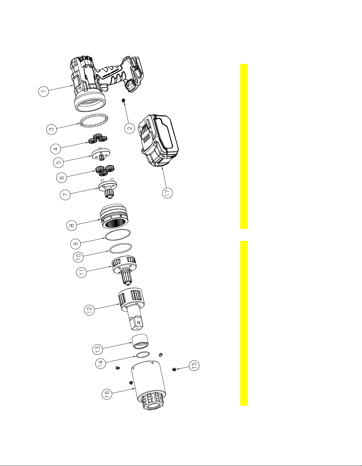
Volta Series Handle (Electrical)
ITEM NAME PART # QTY.
1Black Handle Housing (Set) VT-DH-HOUSING 1
2Transmission Plate VT-ADPTR-7 1
3Battery Locking Piece VT-DH-LOCKPIECE 1
4Battery Lock Pressure Spring VT-DH-LOCKSPRING 1
5Electric Controller (x.xs backoff) VT-DH-ELECT(x.xs)* 1
6Battery Lock Slide VT-DH-LOCKSLIDE 1
7Handle R/L Slide Switch VT-DH-R/LSLIDE 1
818v Motor w/ Pinion VT-DH-MOTORW/PINION 1
9Gear/Motor Flange VT-DH-GEARFLANGE 1
10 Motor Flange Screw VT-DH-GEARFLANGE-SCREW 3
11 Controler Cable Assembly VT-CNTRL-WH01 1
12 Trigger Switch VT-DH-TRIGGER 1
13 Display Cover Label LBL-VT-DISPLAY 1
14 Display Cover VT-CNTRL-COVER 1
15 Controler PCB VT-CNRTL-PCB 1
16 Controler PCB Screw VT-CNTRL-SCREW 2
17 Housing Screw VT-DH-SCREW 7
*Electric controller part numbers:
VT-500, VT-1000, VT-1000-1 VT-DH-ELECT(0.3s)
VT-2000 VT-DH-ELECT(0.6s)
VT-1000E6, VT-3000, VT-6000 VT-DH-ELECT(1.0s)
Part Numbers for Ordering

13
Volta Series Handle
ITEM NAME PART # QTY.
1
Handle
VT-(xx)-DH
1
2
Retaining Ring
VT-ADPTR-9
1
3
Retaining Plate
VT-ADPTR-42
1
4
Planetary Gears
VT-ADPTR-52
3
Gear Carrier Assembly (VT-500)
VT-ADPTR-22-RPGB-H
1
Gear Carrier Assembly (All Other Models)
VT-ADPTR-22
1
6
Ring Gear Screws
VT-ADPTR-8
4
7
Nylon Washer
VT-ADPRT-11
1
8
Ring Gear
VT-ADPTR-32
1
Gearbox Adapter (VT-500)
VT-ADPTR-6-RPGB
1
Gearbox Adapter (All Other Models)
VT-ADPTR-6
1
10
Bearing Ball Retainer
VT-ADPTR-13
1
11
Housing Screws
VT-DH-SCREW
4
Part Numbers for Ordering
5
9

14
VT-500 Series Wrench
ITEM NAME PART # QTY. ITEM NAME PART # QTY.
1
Volta Handle
VT-05-DH-ASSY
1
11
Needle Roller Thrust Bearing
RP3-05-NRB
1
2
Ball Retainer
VT-ADPTR-13
1
12
Thrust Washer A
RP3-05-TRA
1
3
Steel Ball
RP-CM-BB
35
13
Drive Stage Assembly
RP3-05-DSTA
1
4
1st Stage Spur Gear
RP3-05-ST1-G
3
14
Main Bearing
RP3-05-MB
1
5
1st Stage Gear Carrier
RP3-05-ST1
1
15
Main Annulus O-Ring
RP-CM-OR-MA
1
6
2nd Stage Spur Gear
RP3-05-ST2-G
5
16
Drive Annulus O-Ring
RP3-05-OR-DA
1
7
2nd Stage Gear Carrier
RP3-05-ST2
1
17
Drive Annulus Set Screw
RP3-05-SS-DA
4
8
High Speed Annulus
RP3-05-HSA
1
18
Drive Annulus
RP3-05-DA
1
9
High Speed Annulus Dowel
RP3-05-DOWEL
2
19
Lithium Ion Battery
VT-BATT-18V-#.#AH
1
10
Thrust Washer B
RP3-05-TRB
1
Part Numbers for Ordering

15
VT-1000 Series Wrench with 3/4” Drive
ITEM NAME PART # QTY. ITEM NAME PART # QTY.
1
Volta Handle
VT-10-DH-ASSY
1
10
Thrust Washer
RP-10-TW
1
2
Ball Retainer
VT-ADPTR-13
1
11
3rd Stage Assembly
RP-10-ST3A
1
3
Steel Ball
RP-CM-BB
35
12
Drive Stage Assembly
RP-10-DSTA
1
4
1st Stage Spur Gear
RP-10-ST1-G
3
13
Main Bearing
RP-10-MB
1
5
1st Stage Gear Carrier
RP-10-ST1
1
14
Drive Annulus O-Ring
RP-10-OR-DA
1
6
2nd Stage Spur Gear
RP-10-ST2-G
3
15
Main Annulus O-Ring
RP-CM-OR-MA
1
7
2nd Stage Gear Carrier
RP-10-ST2
1
16
Drive Annulus Set Screw
RP-CM-SS-DA
4
8
High Speed Annulus
RP-10.30-HSA
1
17
Drive Annulus
RP-10-DA
1
9
High Speed Annulus Dowel
RP3-05-DOWEL
3
18
Lithium Ion Battery
VT-BATT-18V-#.#AH
1
Part Numbers for Ordering

16
VT-1000 Series Wrench with 1” Drive
ITEM NAME PART # QTY. ITEM NAME PART # QTY.
1
Volta Handle
VT-10-DH-ASSY
1
10
Thrust Washer
RP-10-TW
1
2
Ball Retainer
VT-ADPTR-13
1
11
3rd Stage Assembly
RP-10-ST3A
1
3
Steel Ball
RP-CM-BB
35
12
Drive Stage Assembly
RP-10-DSTA-1
1
4
1st Stage Spur Gear
RP-10-ST1-G
3
13
Main Bearing
RP-10-MB-1
1
5
1st Stage Gear Carrier
RP-10-ST1
1
14
Drive Annulus O-Ring
RP-10-OR-DA-1
1
6
2nd Stage Spur Gear
RP-10-ST2-G
3
15
Main Annulus O-Ring
RP-CM-OR-MA
1
7
2nd Stage Gear Carrier
RP-10-ST2
1
16
Drive Annulus Set Screw
RP-CM-SS-DA
4
8
High Speed Annulus
RP-10.30-HSA
1
17
Drive Annulus
RP-10-DA-1
1
9
High Speed Annulus Dowel
RP3-05-DOWEL
3
18
Lithium Ion Battery
VT-BATT-18V-#.#AH
1
Part Numbers for Ordering
17
VT-2000 Series Wrench
ITEM NAME PART # QTY. ITEM NAME PART # QTY.
1
Volta Handle
VT-20-DH-ASSY
1
10
Main Annulus O-Ring (Large)
RP-20.60-OR-MA
1
2
Ball Retainer
VT-ADPTR-13
1
11
3rd Stage Assembly
RP-20-ST3A
1
3
Steel Ball
RP-CM-BB
35
12
Drive Stage Assembly
RP-20-DSTA
1
4
1st Stage Spur Gear
RP-20-ST1-G
3
13
Main Bearing
RP-20-MB
1
5
1st Stage Gear Carrier
RP-20-ST1
1
14
Drive Annulus O-Ring
RP-20-OR-DA
1
6
2nd Stage Spur Gear
RP-20-ST2-G
3
15
Drive Annulus Set Screw
RP-20.60-SS-DA
4
7
2nd Stage Gear Carrier
RP-20-ST2
1
16
Drive Annulus
RP-20-DA
1
8
High Speed Annulus
RP-20.60-HSA
1
17
Lithium Ion Battery
VT-BATT-18V-#.#AH
1
9
Main Annulus O-Ring (Small)
RP-CM-OR-MA
1
Part Numbers for Ordering

18
VT-3000 Series Wrench
ITEM NAME PART # QTY. ITEM NAME PART # QTY.
1
Volta Handle
VT-30-DH-ASSY
1
14
Drive Annulus Set Screw
RP-CM-SS-DA
4
2
Ball Retainer
VT-ADPTR-13
1
15
Drive Annulus
RP-30-DA
1
3
Steel Ball
RP-CM-BB
35
16
Drive Annulus O-Ring
RP-30-OR-DA
1
4
1st Stage Spur Gear
RP-30-ST1-G
3
17
Drive Stage Assembly
RP-30-DSTA
1
5
1st Stage Gear Carrier
RP-30-ST1
1
18
Drive Stage Thrust Washer
RP-30-DSTA-TW
1
6
2nd Stage Spur Gear
RP-30-ST2-G
3
19
Main Bearing
RP-30-MB
1
7
2nd Stage Gear Carrier
RP-30-ST2
1
20
Annulus Head O-Ring
RP-30-OR-AH
1
8
High Speed Annulus
RP-10.30-HSA
1
21
Annulus Head
RP-30-AH
1
9
High Speed Annulus Dowel
RP3-05-DOWEL
3
22
Retaining Ring
RP-30-RR
1
10
High Speed Thrust Washer
RP-30-HSA-TW
1
23
Annulus Cap O-Ring
RP-30-OR-AC
1
11
3rd Stage Assembly
RP-30-ST3A
1
24
Annulus Cap
RP-30-AC
1
12 4th Stage Assembly RP-30-ST4A 1 25 Annulus Head Screw RP-30-AH-SCREW 4
13 Main Annulus O-Ring RP-CM-OR-MA 1 26 Lithium Ion Battery VT-BATT-18V-#.#AH 1
Part Numbers for Ordering

19
VT-6000 Series Wrench
ITEM NAME PART # QTY. ITEM NAME PART # QTY.
1
Volta Handle
VT-60-DH-ASSY
1
14
4th Stage Assembly
RP-60-ST4A
1
2
Ball Retainer
VT-ADPTR-13
1
15
Drive Annulus O-Ring
RP-60-OR-DA
1
3
Steel Ball
RP-CM-BB
35
16
4th Stage Thrust Washer
RP-60-ST4A-TW
1
4
1st Stage Spur Gear
RP-60-ST1-G
3
17
Drive Stage Assembly
RP-60-DSTA
1
5
1st Stage Gear Carrier
RP-60-ST1
1
18
Drive Stage Thrust Washer
RP-60-DSTA-TW
1
6
2nd Stage Spur Gear
RP-60-ST2-G
3
19
Main Bearing
RP-60-MB
1
7
2nd Stage Gear Carrier
RP-60-ST2
1
20
Annulus Head O-Ring
RP-60-OR-AH
1
8
High Speed Annulus
RP-20.60-HSA
1
21
Annulus Head
RP-60-AH
1
9
Main Annulus O-Ring (Small)
RP-CM-OR-MA
1
22
Retaining Ring
RP-60-RR
1
10
Main Annulus O-Ring (Large)
RP-20.60-OR-MA
1
23
Annulus Cap O-Ring
RP-60-OR-AC
1
11
3rd Stage Assembly
RP-60-ST3A
1
24
Annulus Cap
RP-60-AC
1
12 Drive Annulus Set Screw RP-20.60-SS-DA 4 25 Annulus Head Screw RP-60-AH-SCREW 4
13 Drive Annulus RP-60-DA 1 26 Lithium Ion Battery VT-BATT-18V-#.#AH 1
Part Numbers for Ordering

20
MSDS
This manual suits for next models
6
Table of contents
Other TorcUP Power Tools manuals

TorcUP
TorcUP TXU Series User manual

TorcUP
TorcUP SQ Series User manual

TorcUP
TorcUP ULTRA series Manual

TorcUP
TorcUP SR Series User manual

TorcUP
TorcUP VT Series User manual

TorcUP
TorcUP TU-2 User manual

TorcUP
TorcUP RAPTOR RP Series Setup guide

TorcUP
TorcUP TU Series User manual

TorcUP
TorcUP TXU-2 User manual

TorcUP
TorcUP TX LINK Series Operating manual


Popular Power Tools manuals by other brands


ATD Tools
ATD Tools ATD-109 operating instructions

Equalizer International
Equalizer International Equalizer FA1TM Operator's instruction manual

Max
Max TA551A/16-11 CE Operating and maintenance manual

AP&T
AP&T AP-AC2456 user manual

Heinner
Heinner DBS03 instructions

TE Connectivity
TE Connectivity 2390276-1 instruction sheet