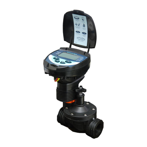
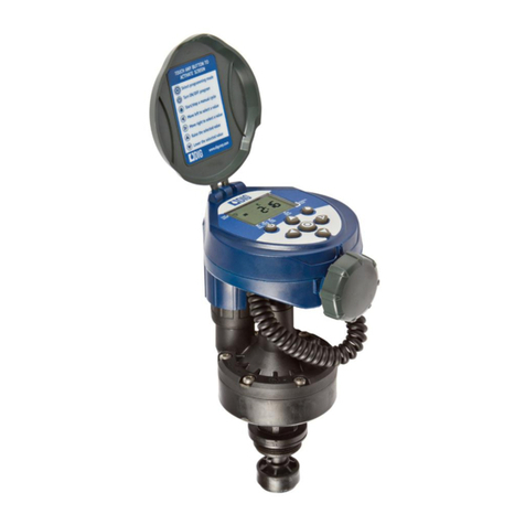
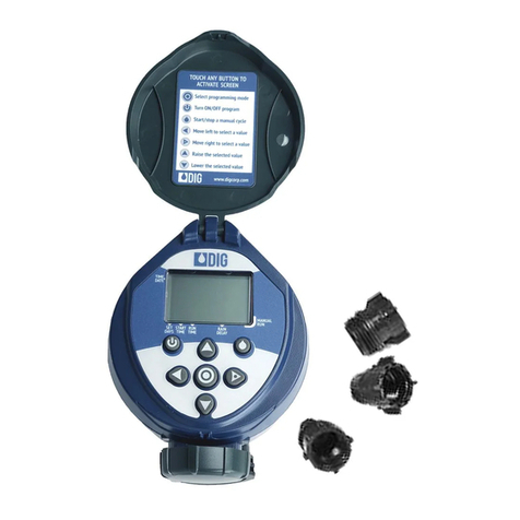
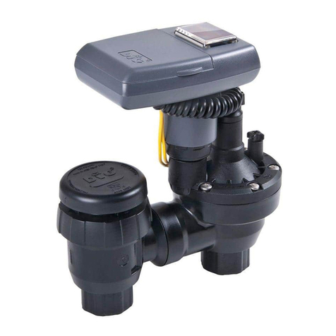
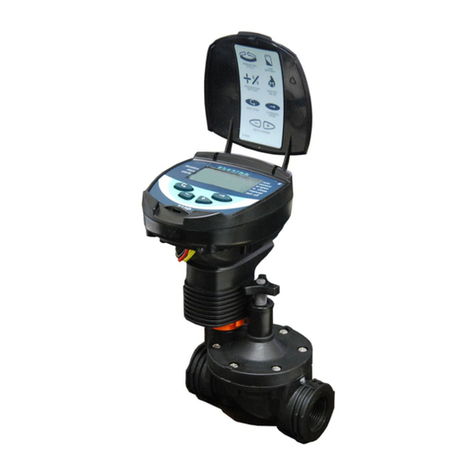
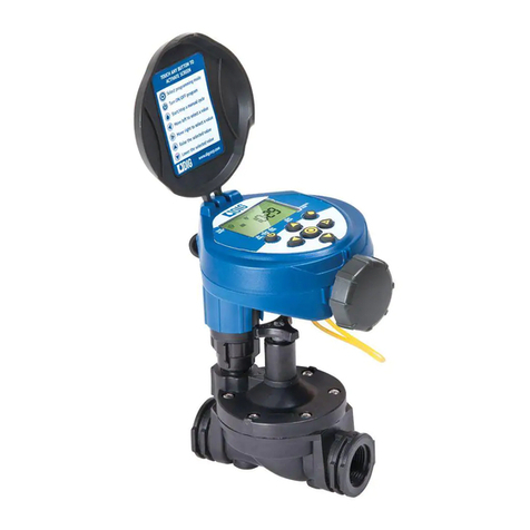
DIG LEIT 4000 Series User manual

LEIT®4000
Ambient Light Powered
Irrigation Controllers
Instruction Manual
INSTRUCTION MANUAL

TABLE OF CONTENTS
A. Introduction ………………………………………………………………………… 1
B. About the LEIT 4000 Controller ……………………………………………………… 1
C. Technical Assistance ………………………………………………………………… 1
D. Copyright and Compliance …………………………………………………………… 1
E. Features …………………………………………………………………………… 1
1. System …………………………………………………………………………………… 2
1.1 Models available …………………………………………………………………… 2
1.2 Parts identification ………………………………………………………………… 2
1.3 USB updater ……………………………………………………………………… 2
1.4 Required system components ……………………………………………………… 3
1.5 Tools and supply requirements ……………………………………………………… 4
2. Installation ……………………………………………………………………………… 4
2.1 Valve installation model 160HE-XXX (2-WAY) ………………………………………… 4
2.2 LEMA Solenoid actuator installation model 1600HE (2-WAY) ………………………… 4
2.3 Wire installation and distance ……………………………………………………… 5
2.4 Controller installation ……………………………………………………………… 5
3. Sensor installation………………………………………………………………………… 5
3.1 Sensor connection to unused station ………………………………………………… 6
3.2 Sensor connection if station is not available ………………………………………… 6
3.3 Compatible sensors ………………………………………………………………… 7
4. Pump or any electrical equipment installation …………………………………………… 7
4.1 RKIT installation to the MV/Pump terminal …………………………………………… 7
4.2 RKIT installation to one of the valve station terminal connectors ……………………… 7
5. Programming …………………………………………………………………………… 10
5.1 Manual run ………………………………………………………………………… 11
5.2 Rain stop/restart …………………………………………………………………… 12
5.3 Monthly budget …………………………………………………………………… 13
5.4 Check status ……………………………………………………………………… 13
5.5 Setup schedule …………………………………………………………………… 14
5.6 Setup system ……………………………………………………………………… 16
6. Troubleshooting ………………………………………………………………………… 19
6.1 LEIT key …………………………………………………………………………… 19
6.2 LEIT controller ……………………………………………………………………… 19
6.3 LEMA solenoid actuator …………………………………………………………… 19
6.4 Hydraulic valves …………………………………………………………………… 20
6.5 Field control wires ………………………………………………………………… 20
7. Warranty ………………………………………………………………………………… 21
8. LEIT control programming quick reference chart …………………………………………… 22
9. USB Updater ……………………………………………………………………………… 24

A. INTRODUCTION
Thank you for purchasing a DIG LEIT®4000 series controller.
This manual describes how to get the LEIT 4000 controller up and running quickly. After reading this manual and
having been familiarized with the basic functionality of the controller, the manual can be used as a reference for
less common tasks in the future.
Please take the time to read through the enclosed instructions and follow them step-by-step.
B. ABOUT THE LEIT 4000 CONTROLLER
The LEIT 4000 Series Controller is an advanced ambient light powered water management irrigation controller that
uses a time tested photovoltaic module which harnesses light energy to generate electricity that is stored and used
to power the controller day and night in any kind of weather.
DIG LEIT irrigation controllers are available in two other models: LEIT X (without radio) or LEIT XRC (with radio
control capability).
The LEIT 4000 irrigation controller has an improved menu base with straightforward programming that allows
for a wide range of irrigation programs. Features include four programs with three start times per valve, manual
runs (both temporary or stored), rain delays for up to 99 days, budgeting up to 200 percent, status checks, history
reports, program setting modification, and more.
C. TECHNICAL ASSISTANCE
Should you encounter any problem(s) with this product or if you do not understand its many features, please refer
to this operating manual first. If further assistance is required, DIG offers the following customer support:
Technical Service USA
• DIG’s Technical Service Team is available to answer questions from 8:00 AM to 5:00 PM (PST) Monday-Friday
(except holidays) at 800-322-9146.
• Specification documents and manuals are available for download at www.digcorp.com.
Customer Assistance Outside the USA
Contact your local distributor.
D. COPYRIGHT AND COMPLIANCE
Copyright 2016 DIG Corporation. All rights reserved. LEIT and LEIT Link are registered trademarks. LEIT 4000, LEIT X
& XRC, LEIT Link Master and LEIT Link Multi-Pro are each trademarks of DIG Corporation.
Patent #: 5,229,649 and 5,661,349
FCC, CE, Canada and Australia compliance
Warning: The user should make no field changes or modifications to the LEIT 4000 controller.
All adjustments and changes must be made at DIG’s facility under the specific guidelines set forth in
our manufacturing process. Any change or modification to the equipment will void the users authority
to operate the unit, and render the equipment in violation of FCC part 15 subpart C, 15.247.
Any tampering with this product will void the warranty.
E. FEATURES
• Operates 4-8 stations and a master valve or pump start without AC power hookup, batteries or conventional
solar panels
• Software in English, Spanish, Italian or French
• 4 programs with 3 start times per program
• Budgeting feature for a yearly watering schedule can be set by month
°Increase or decrease irrigation from 10-200% in 10% increments
• Review status and history reports
• Built to the highest quality control standard (ISO 9002)
°Controller functions and operations are 100% tested
°Controller waterproofing is 100% tested
1

• Non-volatile memory holds programs indefinitely without batteries
• All power is provided by an internal photovoltaic module and microelectronic energy management system
fueled by ambient light
°Functions day or night in all weather conditions and in most outdoor locations
• 365 day calendar with leap year
• Assign-rain, moisture or freeze sensors to an individual valve or to the entire system using
SKIT 8821-4 connector
• Manual watering by station or program
• Environmentally friendly - uses clean power
°No batteries or AC power needed
1. SYSTEM
This chapter explains the components and installation of the LEIT 4000 controller. The LEIT controller must be
installed according to the manufacturer’s recommendations; failure to do so will void the manufacturer’s warranty.
The LEIT 4000 can operate with all discontinued solenoids, such as LEMA 1500-4 and 1500S. DIG recommends all
new installations be done using the 160HE series valves and 1600HE solenoid actuator.
1.1 Models Available
1.1 The LEIT 4000 irrigation controller is available in three models:
• LEIT 4004 4 stations plus MV/Pump
• LEIT 4006 6 stations plus MV/Pump
• LEIT 4008 8 stations including MV/Pump
1.2 If you have purchased a LEIT 4004 or 4006, you have the option of connecting an additional master valve
to your controllers.
1.3 If you have purchased a LEIT 4008, you have the option to configure station 8 as a master valve when you
install a master valve on your system.
1.4 All LEIT 4000 series controllers are fitted with a wiring connector strip that has a maximum of 8 connector
ports for hot wires (stations) and 2 connector ports for common wires.
1.2 Parts Identification
qPVM – Photovoltaic module harnesses light energy and uses it to generate electricity to power the unit day
and night in any kind of weather condition.
wLCD Display – Displays the application stored in the controller.
e Programming Buttons – Use these 4 buttons to program,
modify and review the status of a LEIT 4000 controller.
r Location to insert the LEIT Key – To begin, insert the LEIT
Key to enter the LEIT controller’s programming screens (use 1,
9-volt battery). The LEIT Key is not included.
t Terminal Strip – Up to 11 terminals are available, depending on
model, to connect the valves wires, sensors via the SKIT and the
MV/P.
y USB Connection – for software updates.
LEIT Door and key – To enter the controller use the key (included) to unlock the door and remove it.
1.3 USB Updater
The LEIT 4000 is now supplied with a convenient USB port in order to keep the controller up to date
with new software versions.
If you have a laptop that is running Windows 7 you will be able to make updates in the field without removing
the controller from the pole. If your computer is running Windows Vista, XP or 2000 you will need to remove your
LEIT 4000 and bring it to a computer that has a viable internet connection. Please note that if you are removing the
controller, be sure all valve wires are marked clearly to simplify re-installation.
*At this time Apple OSX is not supported.
Step 1 With a computer that has a viable internet connection, download the LEIT 4000 USB Updater.zip file from
www.digcorp.com/LEIT-4000-software-update.
2
STATION 1
STATION 2
STATION 3
STATION 4
STATION 5
STATION 6
COMMON
COMMON
S/N:
STATION MV/P
q
w
e
t
r
y

Step 2 After the file has completed downloading, unzip it by double clicking on file.
Step 3 Next plug the USB type B into the LEIT 4000 and the USB type A into your computer. If running Windows
7, please skip to step 5.
Step 4 For computers running Windows Vista, XP or 2000, the computer auto-detects that a device has been
connected and will ask you to install the proper drivers in order to establish a connection with the LEIT
4000 controller. Once the necessary drivers have been installed, proceed to the next step.
Step 5 Open up the unzipped 4000 USB Updater folder and double-click to run the LEIT 4000 USB Updater 1XX.
exe file.
Step 6 Follow all instructions on screen to complete the update process of your LEIT 4000 controller.
If you have any questions please call us at 1-800-322-9146 or 760-727-0914.
1.4 Required System Components
To properly install the LEIT controller, the following components will be needed:
1. Control unit: LEIT series controllers programmed with bilingual software versions SW Ver 1.23 and later EE
Ver 1.02 and later (LEIT Key not included).
2. LEIT Key: Programming tool required to enter and program the controller (uses 1, 9-volt alkaline battery).
3. Mounting column: model MCO4000 (short) 32” (81 cm) or MCO4000L (long) 48” (124
cm) steel pipe including mounting tool kit (1 screw, 1 spacing bolt, 1 hex-key 3/16”).
4. Actuator with in-line valve: each solenoid actuator comes complete with in-line
valve (160HE- 075 for 3/4”, 100 for 1”, 150 for 1-1/2” and 200 for 2”).
For drip systems, use a drip zone assembly model P52-075 that includes a
160HE-075 3/4” valve, 155 mesh screen filter and 30 PSI preset pressure regulator.
5. LEMA actuator only: (1600HE) one for each valve being used (see available
adapters for mounting on any brand name valves).
6. 7-solenoid adapters are available to fit most valves:
a. Model 30-920 use with BERMAD 200, HIT 500 and DOROT series 80, GRISWOLD 2000
and DW, BUCKNER VB series
b. Model 30-921, use with RAIN BIRD DV, DVF, PGA, PEB (3/4” and 1” only), GB, EFB-CP,
BPE, PESB (3/4” and 1” only) and ASVF series
c. Model 30-922, use with HUNTER ASV, HPV, ICV, PGV, SRV, IBV and AS VF series
d. Model 30-923, use with WEATHERMATIC 12000 and 21000 series
e. Model 30-924, use with IRRITROL 100, 200B, 205, 217B, 700, 2400, 2500, 2600 series,
TORO 220, P220
f. Model 30-925, use with SUPERIOR 950, HUNTER HBV, TORO 252 (1.5” and larger)
g. Model 30-926, use with RAINBIRD 1 1/2” and 2” PEB and PESB series
7. Optional: Model SKIT 8821-4 connector: if any sensors are used, an
SKIT 8821-4 adapter is required.
8. Optional: Model RKIT 8810S relay: if pumps or any electrical equipment
are used, an RKIT 8810S adapter is required.
3
E1 O-ring
200-014
model #30-494
E2
Short sleeve
model #30-422
E
F1 O-ring
200-014
model #30-494
FD
D1 O-ring
200-015
model #30-494
D2 Sleeve
model #30-424
C
C1 O-ring
200-012
model #30-495
C2
Long sleeve
model #30-423
B
B1 O-ring
200-021
model #03-077
A
A1 O-ring
200-014
model #30-494
A2 Sleeve
model #30-424
G1 O-ring
200-021
model #30-926
G
STATION 1/9
STATION 2/10
STATION 3/11
STATION 4/12
STATION 5/13
STATION 6/14
STATION 7/15
COMMON
COMMON
S/N:
STATION 8 AND 16 OR MV/P
STATION 1/9
STATION 2/10
STATION 3/11
STATION 4/12
STATION 5/13
STATION 6/14
STATION 7/15
COMMON
COMMON
S/N:
STATION 8 AND 16 OR MV/P
LEIT Key
M-Kit

1.5 Tools and Supply Requirement
1. Battery: 9-volt alkaline battery for the LEIT Key
2. Standard wire stripper
3. Flathead screwdriver (9/64” or smaller)
4. Concrete: approximately three 60 lb (27 kg) bags
5. Conventional waterproof wire connectors
2. INSTALLATION
Select the optimum location for the LEIT 4000 controller. If possible locate the controller in open area not adjacent
to a wall or building. We recommend installing a rain sensor with each controller with the use of adapter model
SKIT 8821-4.
2.1 Valve Installation Model 160HE-XXX (2-WAY)
Recommended version is a complete valve assembly including LEMA solenoid actuator with
plastic in-line valve (globe), sizes from 3/4” to 2”.
Maximum static operating pressure is up to 150 PSI.
1. Shut off the mainline to the valve.
2. Install series 160HE-xxx valves with a solenoid actuator according to a valve standard
installation specification (see Figure A on page 7).
3. After installation is completed, turn the water supply on and pressurize the mainline.
The valves will open momentarily and then shut off. Test each valve in manual operation by moving the holder/
handle from left to right to open and right to left to close the valve, making sure that the valve is operating
correctly. The valve should open momentarily and then shut off.
4. Splice the solenoid actuator hot wires (red) to one of the color-coded wires. Splice the solenoid actuator white
wire to the single incoming white (common) wire. Use 2 conventional dry-splice waterproof connectors. Leave
the wires slightly loose on each side so that repairs, if needed, can be carried out easily. Make sure not to
exceed the maximum run recommendation of wire distance (see page 7).
2.2 LEMA Solenoid Actuator Installation Model 1600HE (2-WAY)
Select the appropriate adapter for the valve(s) that will be used (see list on page 5).
The LEMA solenoid actuator operates only with 2-way normally closed valves.
Maximum static operating pressure is up to 150 PSI.
1. Shut off the mainline to the valve.
2. Unscrew the conventional solenoid from the valve and remove the solenoid housing,
solenoid stem, plunger, spring, and O-ring (if necessary).
3. Select the appropriate conversion adapters for the valve(s) then thread and tighten the
conversion adapter clockwise to the compatible valve port, do not over tighten.
4. Make sure that the solenoid holder/handle is not inserted into the solenoid housing,
and then, screw the LEMA 1600HE assembly into the correct adapter. Firmly tighten the
solenoid by hand, but do not over tighten.
5. Slip the LEMA 1600HE sleeve/handle into the solenoid housing. Positioning the solenoid
handle at a 40-45° angel towards the valve creates a manual lever; helpful for manual
on/off.
6. After installation is completed, turn the water supply on and pressurize the mainline.
The valves will open momentarily and then shut off. Test each valve in manual operation
by moving the holder/handle from left to right to open and right to left to close the valve,
making sure that the valve is operating correctly. The valve should open momentarily and
then shut off. If the valve remains open in manual operation, examine the adapter and the
sleeve to see that it is installed correctly and the adapter is firmly secured. Do not over
tighten the LEMA solenoid actuator to the valve and do not cross thread the adapter into
the solenoid cavity
4

NOTE: For all brand name valves with internal manual bleed lever, make sure the lever is in closed
position. Do not move the lever after installing the solenoid with the valve adapter. If the manual lever
on the valve is used, it can damage the adapter or the sleeve causing the valve to
stay open.
7. Splice the solenoid actuator hot wires (red) to one of the color-coded field wires. Splice
the solenoid actuator white wire to the incoming white (common) wire. Use 2 conventional
DRY-SPLICE WATERPROOF CONNECTORS. Leave the wires slightly loose on each
side so that repairs, if needed, can be carried out easily. Make sure not to exceed the
maximum run recommendation of the wire distance (see A1 below).
WARNING: The LEMA solenoid actuators must not be tested with any AC valve tester or DC tester
over 9-volts. If you do so, it will cause irreparable damage to the LEMA solenoid actuator and the
controller unit. Testing the solenoids with equipment rated higher than 9-volts will void the warranty.
2.3 Wire Installation and Distance
Run all direct burial wires along their respective trenches from each valve box to the controller location. Use
selection of color-coded direct burial wires to connect to each solenoid red (hot) wire. Use white (common) wire to
connect to the solenoid’s white (common) wire. Make sure to label each color-coded wire inside the irrigation box
with the designated station number.
MAXIMUM WIRE DISTANCE
Wire gauge recommendation LEMA 1500S SOLENOIDS LEMA 1600 HE SOLENOIDS
14 AWG (2.5 mm2) 1500 feet (300 m) 4,500 feet (1365 m)
12 AWG (4 mm2) 2400 feet (700 m) 7,500 feet (2272 m)
2.4 Controller Installation
1. To install the mounting column, set the curved bottom of the mounting column in a
12” x 12” x 12” (30 x 30 x 30 cm) frame and pour in the three 60 lb (27 kg) bags of
cement (see Figure A). Make sure the column is vertical and the opening in the curved
bottom is accessible and unclogged. All wires should route to the controller through
the bottom of the mounting column (see A1).
NOTE: Make sure the cement pad is dry before continuing with
the installation.
5
LEGEND
qDRY SPLICE CONNECTORS
w18” VALVE BOX WITH COVER
eFINISH GRADE TOP
rDIG REMOTE CONTROL VALVE WITH FLOW
CONTROL AND LEIT DC SOLENOID
MODEL: 160HE-150 1-1/2”
MODEL: 160HE-200 2”
tPVC SCH 40 MALE ADAPTER
yPVC MAIN LINE
uBRICK SUPPORT AT EACH CORNER
iPEA GRAVEL SUMP MINIMUM 3”
oCONTROL WIRE TO OTHER VALVE
1) SWIVEL FITTING FOR EASY CONNECTION
MODEL: 23-152 1-1/2”
MODEL: 23-202 2”
1! PVC SCH 40-45° ELL
160HE-150 1-1/2” and 160HE-200 2” REMOTE CONTROL
VALVE FOR LEIT CONTROLLER ASSEMBLY
Figure A
STATION 1/9
STATION 2/10
STATION 3/11
STATION 4/12
STATION 5/13
STATION 6/14
STATION 7/15
COMMON
COMMON
S/N:
STATION 8 AND 16 OR MV/P
STATION 1/9
STATION 2/10
STATION 3/11
STATION 4/12
STATION 5/13
STATION 6/14
STATION 7/15
COMMON
COMMON
S/N:
STATION 8 AND 16 OR MV/P
Figure A1
LEIT X, XR and XRC Controller Specifications
Section 02810
moc.procgid.www2820-727-067XAF•6419-223-008:enohP
LIGHT ENERGIZED IRRIGATION CONTROLLER
LEIT CONTROL X, XR AND XRC
160HE-160 1-1/2" and 160HE-200 2" REMOTE CONTROL
VALVE FOR LEIT CONTROLLER ASSEMBLY
RAIN SENSOR ASSEMBLY
COLUMN MOUNTED
160HE-075 3/4" AND 160HE-100 1" REMOTE CONTROL
VALVE FOR LEIT CONTROLLER ASSEMBLY
LEGEND
1DRY SPLICE CONNECTORS
2VALVE BOX WITH COVER 12" SIZE
3FINISH GRADE TOP
4DIG REMOTE CONTROL VALVE WITH FLOW
CONTROL AND LEIT DC SOLENOID
MODEL:160HE-150 1-1/2"
MODEL:160HE-200 2"
5PVC SCH 40 MALE ADAPTER
6PVC MAIN LINE
7BRICK SUPPORT AT EACH CORNER
8PEA GRAVEL SUMP MINIMUM 3"
9CONTROL WIRE TO OTHER VALVE
!º SWIVEL FITTING FOR EASY CONNECTION
MODEL:23-152 1-1/2"
MODEL:23-202 2"
!¡ PVC SCH 40-45°ELL
LEGEND
1VALVE BOX WITH COVER 18" SIZE
2DRY SPLICE CONNECTORS
3FINISH GRADE TOP
4DIG VALVE MODEL
3/4" 160HE-075
1" 160HE-100
5SWIVEL FITTING DIG MODEL
3/4" 23-004,1" 23-003
6PVC SCH 40 MALE ADAPTER
7PVC LATERAL LINE
8BRICK SUPPORT AT EACH CORNER
9PEA GRAVEL SUMP – MINIMUM 3"
!º 12 OR 14 GAUGE WIRE
!¡ BACK-UP NPT PVC BALL VALVE
!™ PVC SCH 40 90°ELL
!£ SCH 40 TEE
LEGEND
1"MINI CLIK" RAIN SENSOR
2DIG PLASTIC PIPE CAP
1" PART #23-001 OR 1-1/2" #23-053
WITH HOLE FOR WIRES
3DRILL TWO 3/16" HOLES IN PIPE FOR
SENSOR BRACKET
4(2) #8-32 MACHINE SCREWS WITH
WASHER,LOCK WASHER AND NUT
51" OR 1-1/2" GALVANIZED PIPE
6-10 FEET HIGH
612" X 12" CONCRETE BASE,8" DEEP
MINIMUM
71" OR 1-1/2" PIPE ELBOW
8FINISH GRADE
96" ROUND VALVE BOX
!º SKIT ADAPTER PART #8821-4
USE WITH EACH SENSOR
!¡ TO CONTROLLER OR VALVE
!™ (4) DRY SPLICE CONNECTORS
!£ NORMALLY CLOSED WIRE FROM SENSOR
!¢ COMMON WIRE FROM SENSOR
!∞1" OR 1-1/2" NIPPLE
!§ GRAVEL
LEGEND
1AMBIENT LIGHT POWERED
IRRIGATION CONTROLLER.
MODEL X:10-28 STATIONS
MODEL XR (WITH OPTIONAL RADIO):
4-28 STATIONS
MODEL XRC WITH RADIO REMOTE:
4-28 STATIONS
2TERMINAL STRIP
312 OR 14 GAUGE WIRE
4PROGRAMMING KEY
MODEL #LEIT KEY
535" STEEL MOUNTING COLUMN
MODEL #MCOLXS (SHORT) OR
50" STEEL MOUNTING COLUMN
MODEL #MCOLXL (LONG)
6FINISH GRADE
76-1/2" OF BACKFILL SOIL
8POURED CONCRETE BASE –
1-1/2" CU.FT. INSTALL PER
MANUFACTURER'S INSTALL GUIDE
9DIRECT BURIAL CONTROL WIRES TO
CONTROL VALVES
Part 1 Introduction
1.1LEIT X, XR and XRC controllers are advanced water-management irrigation controllers. The controllers utilize ambient light as the source of energy to
operate up to 28 valves using a low voltage, high efficiency, watertight, 2-way magnetic solenoid actuator that operates at 5-volts. Built to the highest
quality standards (ISO 9002), the LEIT X, XR and XRC controllers have a menu base program with straightforward programming that allows for a wide
range of irrigation programs such as valve grouping, 4 programs with 3 start times, run times up to 6 hours, budget, rain delay, status reports, history
reports, manual runs and more. The controller design uses the most advanced time-tested photovoltaic module, which provides more power to harness
light energy day and night, anytime, anyplace. Used for sprinkler or drip systems, the LEIT X, XR and XRC controllers are commercial quality water
management controllers for any type of environment and for a wide range of uses.
Part 2 Typical Installation
2.1Drawing File no.: LEITX.exe

2. Run the field wires along their respective trenches from the valve
box up to the bottom end of the mounting column. Make sure not
to exceed the maximum recommended wire distance (see chart
for maximum wire distance above). Push the wires up through the
column until at least 12” (30 cm) of wire extends from the top of
the mounting column (see B1).
3. Remove the door from the LEIT controller using the door key
(included) and slide the controller into place on top of the mounting
column. Make sure that 12” (30 cm) of wires are now inside the
controller and cannot slip back down into the column (see C1).
4. Insert the clamp spacer and the screw (included with the mounting
column) into the hole located on the lower left end of the controller.
Tighten the screw with the hex-key (included) until the controller
does not turn or twist and cannot be pulled off of the mounting
column (see D1).
5. Connect the station wires to the controller using a standard wire
stripper. Strip 3/10” of insulation from the tip of each of the station
colored (labeled) wires. Connect the color-coded (hot) wires into
the connector strip labeled with the station number and tighten
the connector screw using a screwdriver. Connect the white
(common) wire into either of the two common wire connectors
labeled “common” located at the lower part of the connector strip
and tighten the connector screw using a screwdriver. If using a
master valve, connect the hot wire from the master valve into the
station labeled “MV/P” (see Figure E1). For pump or other electrical
equipment, see detailed installations on page 10.
3. SENSOR INSTALLATION
The SKIT switch-type, weatherproof sensor adapter provides a quick, reliable way to connect a compatible rain,
freeze, moisture or other normally closed, switch-type sensor. The connection can be made either directly to the
LEIT series irrigation controllers or to one of the micro-powered solenoid actuators.
3.1 Sensor connection to unused station
If there is an unused station on the LEIT controller, connect the sensor directly using a SKIT 8821-4.
a. Run a red (hot) wire from the unused station connector position on the LEIT controller to the red (hot) wire
on the SKIT 8821-4. Then run a white (common) wire from the common connector station position on the
LEIT controller to the white (common) wire on the SKIT. Finally, splice the two SKIT black wires to the
sensor’s two normally closed (N/C) wires (see Figure B, Option 1).
3.2 Sensor connection if station is not available
If station is unavailable, or the controller is too far from the sensor, connect the SKIT 8821-4 to LEMA actuators at
a valve closest to the desired sensor location. This method can be used to minimize excessive wire runs (see Figure
B, Option 2).
b. Choose a valve that is closest to the sensor location. On the installed LEMA series actuator, splice the
red (hot) wire to the SKIT’s red (hot) wire AND to the red (hot) field wire creating a 3-wire connection.
Next, splice the LEMA’s white (common) wire to the SKIT’s white (common) wire and connect both onto
the common field wire. Again, a 3-wire connection should have been created. Finally, splice the two SKIT
black wires to the sensor’s two normally closed (N/C) wires.
6
Figure E1
STATION 1/9
STATION 2/10
STATION 3/11
STATION 4/12
STATION 5/13
STATION 6/14
ST
ATION 7/15
COMMON
COMMON
S/N:
STATION 8 AND 16 OR MV/P
STATION 1/9
STATION 2/10
STATION 3/11
STATION 4/12
STATION 5/13
STATION 6/14
STATION 7/15
COMMON
COMMON
S/N:
STATION 8 AND 16 OR MV/P
Figure C1
STATION 1
STATION 2
STATION 3
STATION 4
STATION 5
STATION 6
STATION MV/P
COMMON
COMMON
S/N:
Spacing
Bolt
Screw
3/16” Hex Key
STATION 1/9
STATION 2/10
STATION 3/11
STATION 4/12
STATION 5/13
STATION 6/14
STATION 7/15
COMMON
COMMON
S/N:
STATION 8 AND 16 OR MV/P
STATION 1/9
STATION 2/10
STATION 3/11
STATION 4/12
STATION 5/13
STATION 6/14
STATION 7/15
COMMON
COMMON
S/N:
STATION 8 AND 16 OR MV/P
Figure B1
Figure D1

3.3 Sensors compatible with LEIT controllers
Rain sensors are the HUNTER MINI-CLIK®and the RAIN BIRD RSD.
Moisture sensors are the IRROMETER, and WEM-B (battery).
Freeze sensor is the HUNTER FREEZE-CLIK®or RAINCLIK™ RFC (rain-freeze combo).
NOTE: Wireless sensors are not compatible with LEIT controllers.
4. PUMP OR ANY ELECTRICAL EQUIPMENT INSTALLATION
If it is required to switch ON a pump, fertilizer injector, fountain or light, two connection options are available using
the RKIT 8810S relay interface module.
The RKIT 8810S units are used to switch 10 amp electrical circuits to a voltage up to 250V AC or 30V DC.
NOTE: RKIT 8810S can be used with LEIT Series 4000, X and XRC.
4.1 RKIT Installation to the MV/Pump Terminal
To operate all the valves with the unit connected to (e.g. pump), connect the RKIT to the MV/Pump terminal
(see Figure C).
4.2 RKIT Installation to One of the Valve Station Terminal Connectors
Operate only the valve number that RKIT has been installed to (e.g. Fountain will turn on/off by only the station
that is using the RKIT).
To install the RKIT, run a red (hot) wire from the RKIT to any of the controller station terminals. Then, run
a white (common) wire from the RKIT to the common terminal connector or if not available, splice it to the
common field wire using a WATERPROOF CONNECTOR. Run the two black wires from the RKIT to the
AC/DC equipment and connect them to the corresponding circuit to be switched (e.g. pump start relay).
Make sure to use WATERPROOF DRY-SPLICE CONNECTORS for all connections.
7
Figure B
OPTION 1
Sensor connected to
controller using SKIT
adapter
OPTION 2
Sensor connected to
a valve using SKIT
adapter

8
CONTROLLER INSTALLATION
Figure C
ELECTRICAL EQUIPMENT RELAY INTERFACE CONNECTION
LEGEND
1. FINISH GRADE
2. 6” ROUND VALVE BOX
3. RKIT ADAPTER PART NO. 8810-S. USE WITH EACH SENSOR
4. RED WIRE TO THE MV/PUMP TERMINAL OR ANY STATION
TERMINAL
5. WHITE WIRE TO THE COMMON TERMINAL
6. DRY SPLICE CONNECTORS (4)
7. TO AC/DC EQUIPMENT OR PUMP START RELAY
NOTE: If the RKIT is connected to any circuit higher than 24-volts, it must be located in its own high
voltage junction box in accordance with local electrical code.
If a pump start relay coil current is greater than 2A (Model 8810S 2A up to August 2007) or 10A (Model 8810S 10A
after August 2007) use a pilot rotary.
WARNING: RKIT cannot be housed in the same box with any low voltage equipment.
Do not connect the RKIT to a circuit higher than 380 VAC, 125 VDC.

9
VALVE INSTALLATION
160HE-075 3/4 AND 160HE-100 1” REMOTE CONTROL
VALVE ASSEMBLY
e
DRY SPLICE WATERPROOF
CONNECTORS
SENSOR INSTALLATION
LEGEND
q“MINI CLIK” RAIN SENSOR.
wDIG PLASTIC PIPE CAP – 1” CAP PART NO. 23-001 OR 1.5”
CAP PART NO. 23-153 WITH HOLE FOR WIRES.
eDRILL TWO 3/16 HOLES IN PIPE FOR SENSOR BRACKET.
r(2) #8-32 MACHINE SCREWS WITH WASHER, LOCK
WASHER AND NUT.
t1” OR 1.5” GALVANIZED PIPE 6 TO 10 FEET HIGH.
y12”x12” CONCRETE BASE 8” DEEP MINIMUM.
u1” OR 1.5” PIPE ELBOW.
iFINISH GRADE.
o6” ROUND VALVE BOX.
1) PART NO. SKIT ADAPTER 8821-4 USE WITH EACH SENSOR.
1! TO CONTROLLER OR VALVE.
1@ (4) DRY SPLICE CONNECTORS.
1# NORMALLY CLOSED WIRE FROM SENSOR.
1$ COMMON WIRE FROM SENSOR.
1% 1” OR 1.5” NIPPLE.
1^ GRAVEL.
RAIN SENSOR ASSEMBLY
COLUMN MOUNTED
w

160HE-150 1-1/2” and 160HE-200 2” REMOTE CONTROL
VALVE FOR LEIT CONTROLLER ASSEMBLY
r
P52-075 3/4” REMOTE CONTROL VALVE ASSEMBLY FOR A DRIP SYSTEM
WITH A 155 MESH FILTER AND 30 PSI PRESET PRESSURE REGULATOR
t
LEIT X, XR and XRC Controller Specifications
Section 02810
moc.procgid.www2820-727-067XAF•6419-223-008:enohP
LIGHT ENERGIZED IRRIGATION CONTROLLER
LEIT CONTROL X, XR AND XRC
160HE-160 1-1/2" and 160HE-200 2" REMOTE CONTROL
VALVE FOR LEIT CONTROLLER ASSEMBLY
RAIN SENSOR ASSEMBLY
COLUMN MOUNTED
160HE-075 3/4" AND 160HE-100 1" REMOTE CONTROL
VALVE FOR LEIT CONTROLLER ASSEMBLY
LEGEND
1DRY SPLICE CONNECTORS
2VALVE BOX WITH COVER 12" SIZE
3FINISH GRADE TOP
4DIG REMOTE CONTROL VALVE WITH FLOW
CONTROL AND LEIT DC SOLENOID
MODEL:160HE-150 1-1/2"
MODEL:160HE-200 2"
5PVC SCH 40 MALE ADAPTER
6PVC MAIN LINE
7BRICK SUPPORT AT EACH CORNER
8PEA GRAVEL SUMP MINIMUM 3"
9CONTROL WIRE TO OTHER VALVE
!º SWIVEL FITTING FOR EASY CONNECTION
MODEL:23-152 1-1/2"
MODEL:23-202 2"
!¡ PVC SCH 40-45°ELL
LEGEND
1VALVE BOX WITH COVER 18" SIZE
2DRY SPLICE CONNECTORS
3FINISH GRADE TOP
4DIG VALVE MODEL
3/4" 160HE-075
1" 160HE-100
5SWIVEL FITTING DIG MODEL
3/4" 23-004,1" 23-003
6PVC SCH 40 MALE ADAPTER
7PVC LATERAL LINE
8BRICK SUPPORT AT EACH CORNER
9PEA GRAVEL SUMP – MINIMUM 3"
!º 12 OR 14 GAUGE WIRE
!¡ BACK-UP NPT PVC BALL VALVE
!™ PVC SCH 40 90°ELL
!£ SCH 40 TEE
LEGEND
1"MINI CLIK" RAIN SENSOR
2DIG PLASTIC PIPE CAP
1" PART #23-001 OR 1-1/2" #23-053
WITH HOLE FOR WIRES
3DRILL TWO 3/16" HOLES IN PIPE FOR
SENSOR BRACKET
4(2) #8-32 MACHINE SCREWS WITH
WASHER,LOCK WASHER AND NUT
51" OR 1-1/2" GALVANIZED PIPE
6-10 FEET HIGH
612" X 12" CONCRETE BASE,8" DEEP
MINIMUM
71" OR 1-1/2" PIPE ELBOW
8FINISH GRADE
96" ROUND VALVE BOX
!º SKIT ADAPTER PART #8821-4
USE WITH EACH SENSOR
!¡ TO CONTROLLER OR VALVE
!™ (4) DRY SPLICE CONNECTORS
!£ NORMALLY CLOSED WIRE FROM SENSOR
!¢ COMMON WIRE FROM SENSOR
!∞1" OR 1-1/2" NIPPLE
!§ GRAVEL
LEGEND
1AMBIENT LIGHT POWERED
IRRIGATION CONTROLLER.
MODEL X:10-28 STATIONS
MODEL XR (WITH OPTIONAL RADIO):
4-28 STATIONS
MODEL XRC WITH RADIO REMOTE:
4-28 STATIONS
2TERMINAL STRIP
312 OR 14 GAUGE WIRE
4PROGRAMMING KEY
MODEL #LEIT KEY
535" STEEL MOUNTING COLUMN
MODEL #MCOLXS (SHORT) OR
50" STEEL MOUNTING COLUMN
MODEL #MCOLXL (LONG)
6FINISH GRADE
76-1/2" OF BACKFILL SOIL
8POURED CONCRETE BASE –
1-1/2" CU.FT. INSTALL PER
MANUFACTURER'S INSTALL GUIDE
9DIRECT BURIAL CONTROL WIRES TO
CONTROL VALVES
Part 1 Introduction
1.1LEIT X, XR and XRC controllers are advanced water-management irrigation controllers. The controllers utilize ambient light as the source of energy to
operate up to 28 valves using a low voltage, high efficiency, watertight, 2-way magnetic solenoid actuator that operates at 5-volts. Built to the highest
quality standards (ISO 9002), the LEIT X, XR and XRC controllers have a menu base program with straightforward programming that allows for a wide
range of irrigation programs such as valve grouping, 4 programs with 3 start times, run times up to 6 hours, budget, rain delay, status reports, history
reports, manual runs and more. The controller design uses the most advanced time-tested photovoltaic module, which provides more power to harness
light energy day and night, anytime, anyplace. Used for sprinkler or drip systems, the LEIT X, XR and XRC controllers are commercial quality water
management controllers for any type of environment and for a wide range of uses.
Part 2 Typical Installation
2.1Drawing File no.: LEITX.exe
LEGEND
qDRY SPLICE WATERPROOF CONNECTORS
w18” VALVE BOX WITH COVER
eFINISH GRADE TOP
rDIG REMOTE CONTROL VALVE WITH FLOW
CONTROL AND LEIT DC SOLENOID
MODEL: 160HE-150 1-1/2”
MODEL: 160HE-200 2”
tPVC SCH 40 MALE ADAPTER
yPVC MAIN LINE
uBRICK SUPPORT AT EACH CORNER
iPEA GRAVEL SUMP MINIMUM 3”
oCONTROL WIRE TO OTHER VALVE
1) SWIVEL FITTING FOR EASY CONNECTION
MODEL: 23-152 1-1/2”
MODEL: 23-202 2”
1! PVC SCH 40-45° ELL
5. PROGRAMMING
This chapter explains the controller buttons hierarchy and how to review, modify settings, program the controller,
or perform a Manual Run. To enter the controller, the user needs a LEIT KEY. Insert the LEIT KEY into the controller
key slot and follow the steps below. After the information on the screen comes to view, the user can select the
language, then review, program, modify settings or perform a Manual Run. For the Programming Quick Reference,
see section 8 or inside the door panel on the controller.
The controller is programmed with the aid of 4 buttons:
Use to accept the desired programming mode, select a parameter and raise (increase) the value
of the selected parameter.
Use to deselect a parameter and lower (decrease) the value of the selected parameter.
Use to move the cursor to left.
Use to move the cursor to right.
To move between applications (left to right) use the right or left arrow buttons. To enter an application
(Moving up) uses the YES button.
10

INSERT LEIT KEY INTO THE SOCKET IN THE UPPER LEFT CORNER OF THE CONTROLLER.
The above screens appear while the controller is charging.
NOTE: If the controller is being programmed for the first time under a low light level it may take up to
5 minutes to charge the controller using the LEIT Key.
The below screens appear and alternate when the LEIT controller is fully charged. When the characters are
most readable, press to select the language to use and continue to the next screen.
This screen identifies the controller model and the number of
stations it has. Press to continue.
This screen appears identifying the software versions that are
installed in the controller. Press to continue.
This screen appears with the date and time. If the controller is
being programmed for the first time, it will not display the correct
time and date. Update this screen in the next few steps.
Press to continue.
5.1 MANUAL RUN
Setting up a Manual Run.
The Manual Run is useful for checking the proper operation of stations (especially after installation), for applying
additional water as required, or for testing the valves.
The first option available on the main menu is the Manual Run option.
The Manual Run feature allows one to test a selected valve, select a temporary program or run a stored program.
Note that at the completion of Manual Run any programmed irrigation
schedule is cancelled.
Manual Run feature overrides any sensor control, but not Budgeting.
Press to select Manual Run or skip Manual Run and move to the next option by pressing or .
You have the option to run any of the stored programs (assuming that they have been programmed) or to set
up and run a temporary program. For example, to set a temporary program, underscore Temp by pressing
Charging
Please wait
Cargando
Espera por favor
Press YES when
most readable
Cuando lea mejor
presiona YES
SW Ver 0.XX
EE Ver 0.XX
MON 01/01/00
12:01 am
LEIT 4000 C-04
11
MANUAL
RUN?

12
or and select temp by pressing , then press
or button again and underscore OK, press and the next
screen will appear.
Press or to underscore the hour or minute digits, then
press or to adjust the runtime. When finished, press
or to underscore OK and press to continue. Follow
the same procedure for the remaining valves. To skip any valve,
simply set the runtime to 0 and press to continue. In this option you will need to pass through all the
valve numbers.
Press to start the Manual Run, (if you are standing within the
spray area, remove the LEIT Key, replace and lock the LEIT 4000
door to protect the controller and move out of the spray area).
The LEIT 4000 will start the Manual Run in approximately one
minute and will run each valve for the programmed duration.
To STOP the Manual Run prematurely, re-insert the LEIT Key, press until you see the Manual Run display.
Press again to view the “Stop Manual Run” screen.
Select Yes by pressing or and press ,then
underscore OK and press , the following screen will appear.
Ok is underscored, press and the Manual Run will stop within
60 seconds. The screen will return to the Manual Run menu.
Press to continue to the next step.
5.2 RAIN STOP/RESTART
Setting up a temporary suspension of all irrigation programs.
The Rain Stop feature is used to temporarily suspend all irrigation
programs. For example, during rainy weather, regularly scheduled
programs can be stopped for periods from 1-99 days. At the end of the
designated period the regularly scheduled programming will resume
automatically.
To enter Rain Stop/Restart press . Press to skip Rain Stop and to move to the next feature.
The Password screen provides the user security against unauthorized changes being made to the system.
The Default password is AAA. If the password has not been changed press to continue. If the
password has been changed, enter the new password to continue.
To enter the new password press or and underscore
the digit to be changed, then press or to select the
appropriate letter. Repeat the steps for each letter. When finished,
Valve #1___0:01
Runtime:
s
t
s
t
s
t
Prog Will Start
Within 1 Min.
Prog Will Stop
Within 1 Min.
Stop Manual Run?
lYes l No
Run Prog. lNone
lStored l Temp
RAIN STOP /
RESTART?
Password: AAA
s
t
s
t
s
t

press or to underscore OK. Press to continue.
To implement a Rain Stop press or and underscore 0
days. Press or and enter the number of days needed to
suspend irrigation (from 1-99 days). Press or to underscore OK. Press to continue.
Rain Stop will cancel itself automatically at 12 AM on the last day of the programmed setting.
If Rain Stop is active it can be cancelled manually anytime in the Cancel Rain Stop screen. Once there, press
or to underscore Yes and press to select. Press or again to underscore OK. Press
to continue, this will bring back the Rain Stop screen.
5.3 MONTHLY BUDGET
Instead of changing duration for each program, you can use the
Monthly Budget feature to increase or decrease the amount of water
used during seasonally dry or wet periods on a monthly basis. Budget
adjustments can range from 10% to 200% of your set time in 10%
increments. The LEIT 4000 will automatically adjust the programmed
duration for each valve according to the entered Budget per month.
At this display, press .
Press the or button to underscore the percentage digits,
press the or to increase or decrease the percentage
(in increments of 10%). Then press the or button to
underscore OK and press to advance to the next month.
Repeat this procedure to enter the desired Budgets for the
remaining months. To skip a month, simply press . In this
procedure you will need to pass thru the 12 months to return to
Monthly Budget. You can enable or disable your stations to be budgeted in the Setup System menu
(see page 17).
Press the to continue to the next step.
5.4 CHECK STATUS
This feature allows you to review the unit’s time, date and sensor setup. Status also reports the current
month’s watering time totals for each station as well as those for the previous month.
1. Press .
Reports on current date and time of day.
2. Press to review sensor setup.
Reports on sensors currently in use, if any.
13
Cancel Rain Stop?
lYes l No
MONTHLY
BUDGET?
JAN 100%
Budget:
s
t
s
t
Stop for 00 Days
s
t
s
t
CHECK
STATUS?
SAT 01/01/00
12:04 am

3. Press to review valve number current month uses.
Reports how much time was logged on each of your valves
during the current month.
4. Press to review the individual log for each valve. Press
after the last valve report to review the previous month
log for each valve.
5. Reports how much time was logged on each valve during the
previous month. Press to review the individual log for
each valve. Press after the last valve report to return to
the Check Status screen.
Press the to continue to the next step.
5.5 SETUP SCHEDULE
This feature allows you to schedule up to four separate programs for each station, each with up to three
individual start times per day.
Press to enter the password screen.
Passwords are provided to give the user security against
unauthorized changes being made to the system. If you are
programming the controller for the first time the default password
is AAA. If you wish, you can customize your password in the
System Setup. For now underscore OK and press to go to the next step.
For example if the controller has been programmed with new password (ABC), to enter your password,
press or to underscore the first letter and press or
to select A. Repeat the step for each letter, then underscore
OK by using or and press to go to select a program
number.
Program # 1 is a default program. To select additional programs underscore the program number by using
or and press , then press or to underscore OK and press again to select the
program type in the next screen.
NOTE: Program will not run unless you activated the program number in the system setup.
Program type options include:
Every- lets you operate stations from once a day to once every 39 days.
14
Sensor is
Unused.
Valve #_____ Use This
Month: 0:37
Valve #_____ Use Last
Month: 3:50
Setup
Schedule?
Program Number:
l 1 l 2 l 3 l 4
Password: AAA
s
t
s
t
s
t

Even- every even numbered day
Odd- every odd numbered day
MTWTFSS- lets you select specific day(s) of the week to irrigate.
Underscore the preferred option by using or , then press
. Repeat using or and underscore OK and press again. If you select MTWTFSS, you’ll
get the following screen to select the day of the week:
Choose one or more days you want the controller to operate by
underscoring the appropriate box under the preferred day using
or and press to accept. The selected days will
show a checkmark instead of the empty boxes. Repeat the steps again to select other days. Underscore OK
by using the or and press to go to Start Time.
First start time: You can select up to three start times a day
(including AM or PM). To program the first start time underscore
the appropriate digit using the or and press or
to change the hour. Repeat the steps again to change minute or
AM/PM. Repeat the steps to underscore OK and press to go to the second start time.
If you wish to run a second start time, underscore Yes using
or and press , then repeat the steps again and
underscore OK and press again to go to second start time
set up.
You may set a second and after that a third start time, by
repeating the steps above. You can later cancel any of the
additional start times simply by selecting No instead of Yes.
Underscore OK and press to enter duration for each valve.
Programming Runtime for each valve: (You can set a runtime from 1 minute to 5 hours and 59 min).
Underscore the appropriate digits using the or and
press or to change the hour or minute. Repeat the steps
and underscore OK and press to go to valve # 2. Follow the
same procedure for the remaining valves. To skip a valve, simply
set the duration to zero.
Remember that the duration for each valve will be repeated with
each of the three start times if selected.
15
l Every l Even
l MTWTFSS l Odd
Water MTWTFSS
Days: nnnnnnn
1st 12:00 am
Start s
t
s
t
s
t
s
t
s
t
2nd Start Time?
lYes lNo
2nd 12:00 am
Start
s
t
s
t
s
t
s
t
s
t
Valve #____ 0:01
Runtime: s
t
s
t
s
t

Once you have completed program 1, you’ll find yourself back in the Setup Schedule display. Press if
you want to repeat the setup procedure, to enter another program or press or to make corrections
to the existing program OR press the to continue to the next step.
5.6 SETUP SYSTEM
This part of the menu enables you to set the correct time and date, activate or de-activate programs, change
passwords, etc.
Press to enter SETUP SYSTEM.
Press or enter the correct password if it has been
customized. (This screen will NOT be displayed if you have
already entered the password in the SETUP SCHEDULE menu.)
* If you have to enter a customized password, press the left arrow
button to underscore the first digit then enter the first letter or
number of the password using or , scroll through the alphabet and numbers. When the correct letter
or number has been selected, press to jump to the next digit and repeat step for the second and third
digit. When your password is shown correctly on the screen press to underscore OK and press to
enter the new password setup and go to the next screen.
In Setup System if all the information on the screen is correct, you may skip any of the following screens by
pressing .
To set the time, underscore the appropriate digits using or
and press or to change the setting. When finished,
underscore OK and press to go to set the date.
To set the date, underscore the appropriate digits using or
and press or to change the setting. Repeat the
steps as needed and when finished, underscore OK and press
to activate program.
In this step, up to four independent programs can be activated.
Number 1 is factory activated (checked). To enable the controller
to activate or cancel any of the stored programs simply add or
remove the check marks by underscoring the appropriate boxes
using or and pressing . Repeat the steps as
needed, underscore OK and press to proceed to the valve options screen.
16
Password: AAA
Time: 12:04 am
s
t
s
t
s
t
s
t
s
t
Setup
System
Date: 01/01/00
s
t
s
t
s
t
s
t
s
t
s
t
Active 1 2 3 4
Progs: 4nnn

17
NOTE: Scheduled programs will not run unless you activated the appropriate program number in
this screen.
This setting has two options for each valve.
Option one, MV/P: if checked, the valve # will operate with an
installed master valve or pump. To switch on an installed MV/P use or to underscore MV/P and
press to checkmark the box then underscore OK and press to move to the next screen or…
Option two, Budget: if checked, the valve # will be affected by the monthly budget setting. All valves
are budgeted by default, if you wish to deactivate the budget, repeat the steps to uncheck the marks
under budget. Press and underscore OK. Repeat the same procedure for the remaining valves then
underscore OK and press to move to the next screen.
This setup indicates whether or not a sensor is activated and
in use: if you install a sensor, use or to underscore
Yes and press the button, then press or to
underscore OK and press to enter sensor location.
This setup indicates a sensor location.
If you selected YES in the “Sensor in Use” screen, you must
indicate which station will have the SKIT and sensor(s) connected
to it. Press or to underscore MV/P or other, press
, then use or to underscore OK and press again to
go to next screen and specify which station the sensor(s) is/are connected.
* MV/P indicates that the sensor is connected to the master valve, “Other” indicates that the sensor is
connected to one of your stations.
If you selected “Other” you must now specify which station
number the sensor(s) is/are connected to. Press or
to underscore the number and press or to enter the
correct station #. Then press or to underscore OK and
press to go to sensor governing.
Valve #1 Options:
nMV/P 4Budget
Sensor in Use?
lYes lNo
Sensor Location:
l MV/P lOther
Sensor 1
Location: s
t

18
At this screen, you can set up any or all of the installed valves
to be switched off when the sensor is triggered. Checkmark
the boxes next to the station numbers that you wish to be
governed by the sensor by using or and underscore the
appropriate box, by pressing to checkmark the box then underscore OK using or and press
to go to change password screen.
If an installed switch type sensor is triggered, any valve that is checkmarked and is currently “ON”
will complete its programmed runtime. All further valve operations will be prevented until the sensor
deactivates and allows watering again.
You may change the default password (AAA) to any three-digit
combination of letters or numbers. Just underscore Yes, using
or , then press the to underscore OK using or
and press to enter your new password screen.
Enter your new password: Press or to underscore the
digits you want to change, use or buttons to change
the password. When finished, write down the password so as not
to forget it.
Underscore OK using or and press to exit. This will
bring you back to the Setup System screen. Press to QUIT
the programming session.
Remember that any person who makes changes to the watering schedule or the setup, needs to enter the
new password.
If you’re ready to quit programming, press and remove the
LEIT KEY.
If the above screens have been completed successfully, your
LEIT 4000 is now fully operational 24 hours a day!
Sensor 41 n2
Governs: n3
Change Password?
lYes lNo
Enter NEW AAA
Password: s
t
s
t
s
t
QUIT
LEIT-4000?
Remove
LEIT-Key
This manual suits for next models
3
Table of contents
Other DIG Controllers manuals
