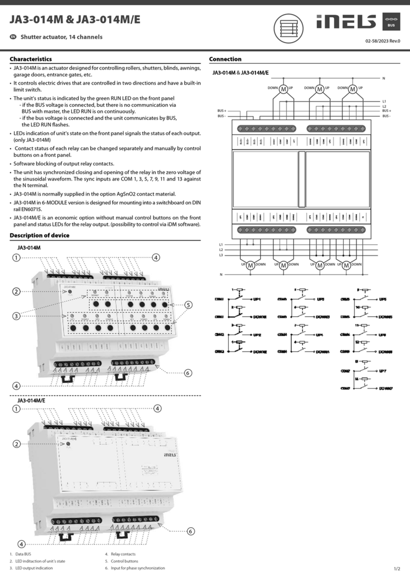
manuals.online logo
Brands
  1. Home
  2. •
  3. Brands
  4. •
  5. iNels
  6. •
  7. Controllers
  8. •
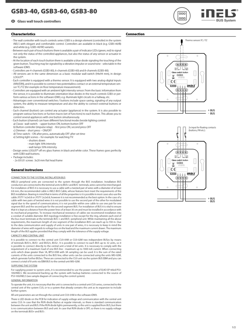
  9. iNels RFWB-20/G User manual

iNels RFWB-20/G User manual

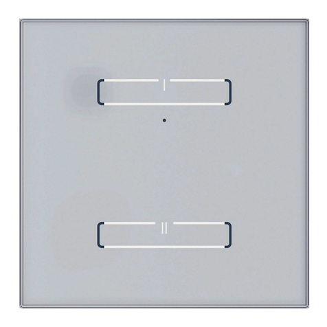
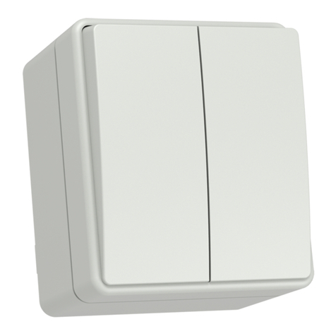
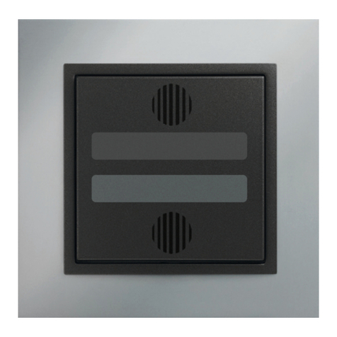
RFWB-20/G, RFWB-40/G
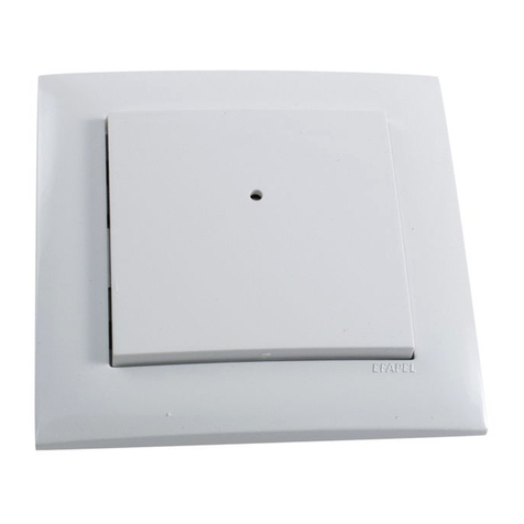
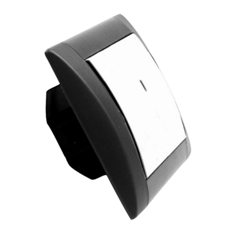
Wireless wall controller
EN
02-13/2019 Rev.0
1 / 2
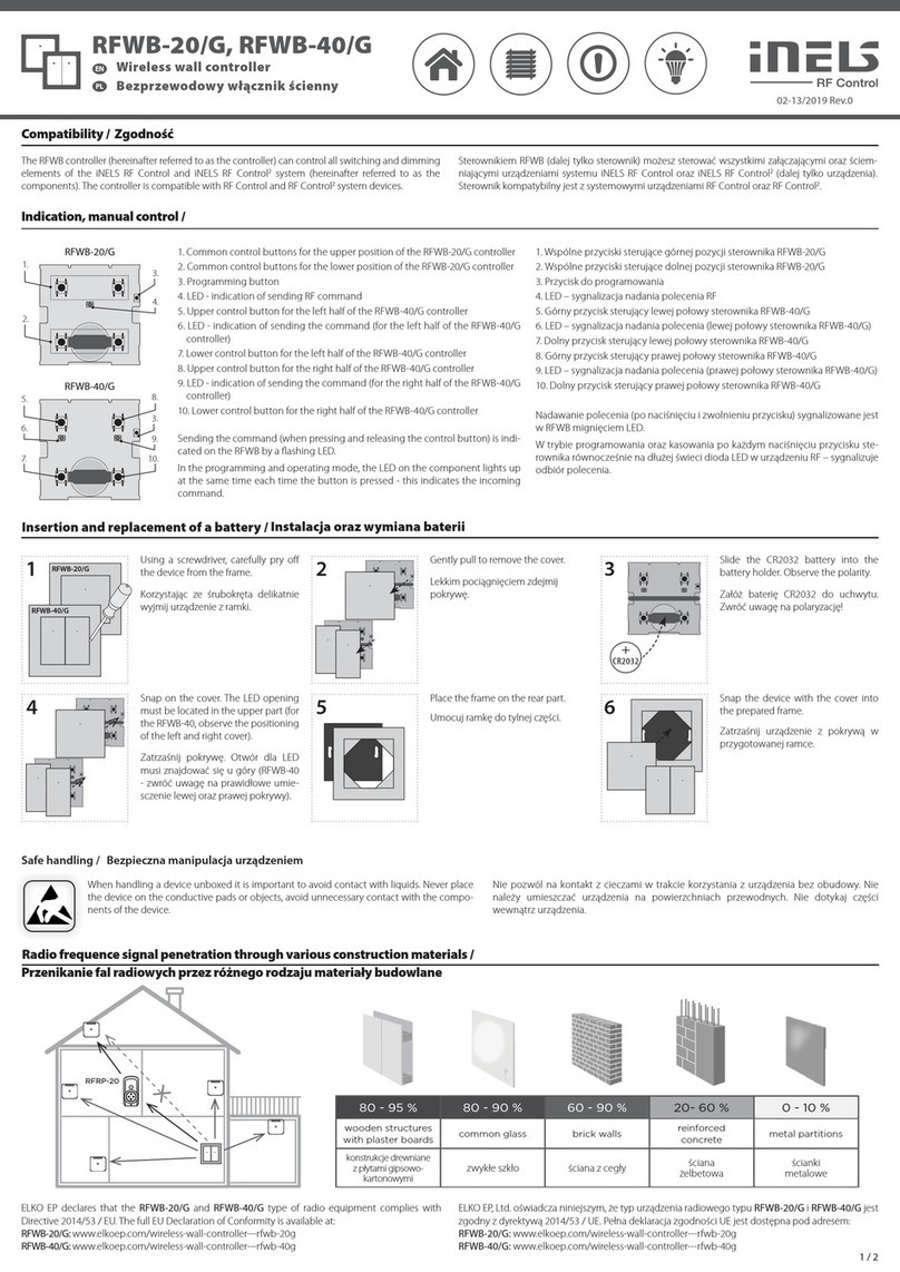
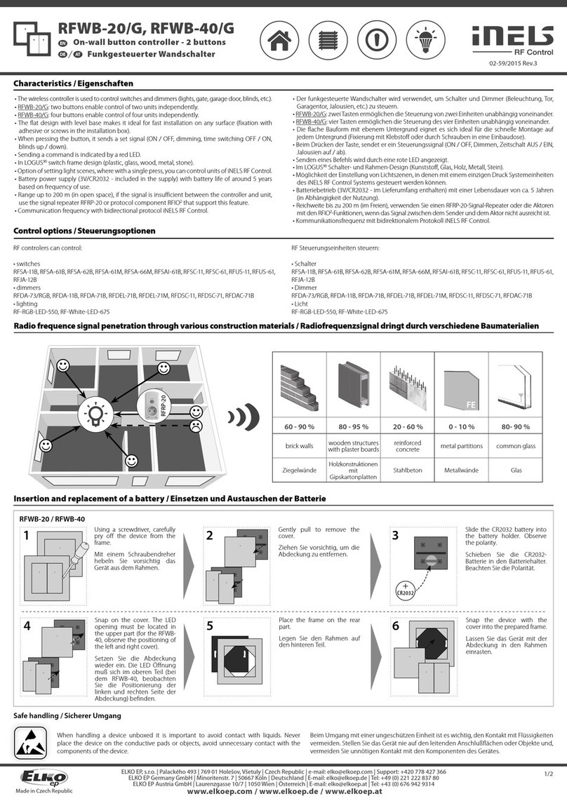
Indication, manual control /
1. Common control buttons for the upper position of the RFWB-20/G controller
2. Common control buttons for the lower position of the RFWB-20/G controller
3. Programming button
4. LED - indication of sending RF command
5. Upper control button for the left half of the RFWB-40/G controller
6. LED - indication of sending the command (for the left half of the RFWB-40/G
controller)
7. Lower control button for the left half of the RFWB-40/G controller
8. Upper control button for the right half of the RFWB-40/G controller
9. LED - indication of sending the command (for the right half of the RFWB-40/G
controller)
10. Lower control button for the right half of the RFWB-40/G controller
Sending the command (when pressing and releasing the control button) is indi-
cated on the RFWB by a flashing LED.
In the programming and operating mode, the LED on the component lights up
at the same time each time the button is pressed - this indicates the incoming
command.
1.
2.
3.
4.
RFWB-20/G
5.
7.
3.
9.
6.
8.
10.
RFWB-40/G
Compatibility /
4 5 6
3
+
CR2032
When handling a device unboxed it is important to avoid contact with liquids. Never place
the device on the conductive pads or objects, avoid unnecessary contact with the compo-
nents of the device.
Insertion and replacement of a battery /
Safe handling /
21 RFWB-20/G
RFWB-40/G
Using a screwdriver, carefully pry off
the device from the frame.
Gently pull to remove the cover. Slide the CR2032 battery into the
battery holder. Observe the polarity.
Place the frame on the rear part. Snap the device with the cover into
the prepared frame.
Snap on the cover. The LED opening
must be located in the upper part (for
the RFWB-40, observe the positioning
of the left and right cover).
The RFWB controller (hereinafter referred to as the controller) can control all switching and dimming
elements of the iNELS RF Control and iNELS RF Control2system (hereinafter referred to as the
components). The controller is compatible with RF Control and RF Control2system devices.
Radio frequence signal penetration through various construction materials /
80 - 95 % 80 - 90 % 60 - 90 % 20- 60 % 0 - 10 %
wooden structures
with plaster boards common glass brick walls reinforced
concrete metal partitions
ELKO EP declares that the RFWB-20/G and RFWB-40/G type of radio equipment complies with
Directive 2014/53 / EU. The full EU Declaration of Conformity is available at:
RFWB-20/G: www.elkoep.com/wireless-wall-controller---rfwb-20g
RFWB-40/G: www.elkoep.com/wireless-wall-controller---rfwb-40g
x
RFRP-20
Vezeték nélküli fali vezérlő
HU
Ha a dobozból kivett panellal dolgozik, akkor ügyeljen arra, hogy semmiképpen ne
érintkezzen folyadékkal. Soha ne tegye elektromosan vezető alátétekre, tárgyakra és ne
érintse meg feleslegesen a panel elektromos alkatrészeit.
Az elem behelyezése és cseréje
Az eszköz biztonságos kezelése
Csavarhúzó segítségével óvatosan ve-
gye ki az eszközt a keretből.
Óvatosan vegye le a fedlapot.
Helyezze be az új CR2032 elemet.
Ügyeljen a polaritásra.
Pattintsa vissza a fedlapot. A LED a fel-
ső részben legyen (figyeljen az RFWB-
40 bal és jobb billentyűjének helyére.
Helyezze a keretet a hátlapra.
Pattintsa az eszközt az előkészített
keretbe.
Az RFWB fali vezérlő (a továbbiakban: vezérlő) vezérelheti az iNELS RF Control és az iNELS RF Control2
rendszer összes kapcsoló- és dimmer egységét (a továbbiakban: egységek). A vezérlő kompatibilis az
RF Control és az RF Control2rendszer egységeivel.
A rádiófrekvenciás jel átvitele különböző építőanyagokon keresztül
téglafal
fa és gipszkarton
szerkezetek vasbeton fém válaszfalaknormál üveg
Az ELKO EP, s.r.o. kijelenti, hogy az RF Key típusú rádióberendezés megfelel a 2014/53/EU
irányelvnek. Az EU-megfelelőségi nyilatkozat teljes szövege elérhető a következő weboldalon:
www.elkoep.hu/hordozhato-rf-key
1. Közös vezérlőgombok az RFWB-20/G vezérlő felső pozíciójához
2. Közös vezérlőgombok az RFWB-20/G vezérlő alsó pozíciójához
3. Programozás gomb
4. LED - RF parancs küldésének jelzése
5. Az RFWB-40/G vezérlő bal oldali felső vezérlőgombja
6. LED - a parancs küldésének jelzése (az RFWB-40/G vezérlő bal oldalán)
7. Alsó vezérlőgomb az RFWB-40/G vezérlő bal oldalához
8. Felső vezérlőgomb az RFWB-40/G vezérlő jobb oldalához
9. LED - a parancs küldésének jelzése (az RFWB-40/G vezérlő jobb oldalán)
10. Alsó vezérlőgomb az RFWB-40/G vezérlő jobb oldalához
A parancs elküldését (a vezérlőgomb lenyomásakor és elengedésekor) az
RFWB-n villogó LED jelzi.
Programozási és törlési módban, a gomb minden egyes megnyomásakor az RF
egység LED-je hosszú ideig világít, jelezve a parancs megérkezését.
Kompatibilitás
Made in Czech Republic
Programming /
Snap the device with the cover into
the prepared frame.
2 3
PROG > 1s
1 x
4


5
PROG < 1s
1 x
1RFWB-20/G
RFWB-40/G
6 7 8
xxxxxx
Assignment of system components /
address / The address on the back of the controller is used for assignment to the system
components.
Press of programming button on ac-
tuator for 1 second will activate actua-
tor RF into programming mode. LED
is flashing in 1s interval.
Gently pull to remove the cover.Using a screwdriver, carefully pry off
the device from the frame.
Press of programming button on
actuator shorter then 1 second will
finish programming mode.
Snap on the cover. The LED opening
must be located in the upper part (for
the RFWB-40, observe the positioning
of the left and right cover).
Hold the programming button on the RFWB. Press the selected control button on the RFWB according
to the desired function (for more information on individual functions and programming, see the manual
of the specific component). There must be a lapse of 1 second between individual presses. Then release
the programming button.
Place the frame on the rear part.
RFWB-20/G RFWB-40/G
Supply voltage:
Transmission indication:
Number of control buttons:
Programming button:
Transmitter frequency:
Signal transmission method:
Range in free space:
Other data
Operating temperature:
Operating position:
Mounting:
Protection:
Contamination degree:
Dimensions:
LOGUS90 frame - plastic:
LOGUS90 frame
- metal, glass, wood, granite:
Weight:
Related standards:
Technical parameters /
* Comes with plastic frame, without battery.
Attention:
No installation into multi-frames.
When you instal iNELS RF Control system, you have to keep
minimal distance 1 cm between each units.
Between the individual commands must be an interval of
at least 1s.
Instruction manual is designated for mounting and also for user of the device. It is
always a part of its packing. Installation and connection can be carried out only by a
person with adequate professional qualification upon understanding this instruction
manual and functions of the device, and while observing all valid regulations. Trouble-
free function of the device also depends on transportation, storing and handling. In
case you notice any sign of damage, deformation, malfunction or missing part, do
not install this device and return it to its seller. It is necessary to treat this product and
its parts as electronic waste after its lifetime is terminated. Before starting installa-
tion, make sure that all wires, connected parts or terminals are de-energized. While
mounting and servicing observe safety regulations, norms, directives and professional,
and export regulations for working with electrical devices. Do not touch parts of the
device that are energized – life threat. Due to transmissivity of RF signal, observe cor-
rect location of RF components in a building where the installation is taking place.
RF Control is designated only for mounting in interiors. Devices are not designated
for installation into exteriors and humid spaces. The must not be installed into metal
switchboards and into plastic switchboards with metal door – transmissivity of RF
signal is then impossible. RF Control is not recommended for pulleys etc. – radiofre-
quency signal can be shielded by an obstruction, interfered, battery of the transceiver
can get flat etc. and thus disable remote control.
The company ELKO EP, as the manufacturer, is entitled to make technical modificati-
ons to the product, in the technical specification and product manual, without prior
notification.
Warning /
ELKO EP, s.r.o. | Palackého 493 | 769 01 Holešov, Všetuly | Czech Republic | e-mail: [email protected] | Support: +420 778 427 366
ELKO EP Hungary Kft. | Hungária krt. 69 | 1143 Budapest | Magyarország | e-mail: [email protected] | Technikai támogatás: +36 1 40 30 132
www.elkoep.com / www.elkoep.hu
Tápfeszültség:
Átvitel jelzése:
Vezérlőgombok száma:
Programozás gomb:
Frekvencia:
Jelátvitel módja:
Hatótávolság nyílt terepen:
További adatok
Működési hőmérséklet:
Működési helyzet:
Felszerelés:
Védettség:
Szennyezettségi fok:
Méretek:
LOGUS90 keret - műanyag:
LOGUS90 keret
- fém, üveg, fa, gránit:
Tömeg:
Vonatkozó szabványok:
3Vbattery / elem CR 2032
red / piros LED
2 4
1
866 MHz, 868 MHz, 916 MHz
unidirectionally addressed message / egyirányú címzett üzenet
up to / legfeljebb 200 m
-10 ... +50 °C
any / tetszőleges
glue, screws / ragasztás, csavarozás
IP20
2
85 x 85 x 16 mm
94 x 94 x 16 mm
55 g* 55 g*
EN 60669, EN 300220, EN 301489 R&TTE Directive, Order. No 426/2000
Coll. (Directive 1999/EC) / EN 60669, EN 300 220, EN 301 489 irányelv RTTE,
NVč.426/2000Sb (irányelv 1999/ES)
Technikai paraméterek
* Normál műanyag kerettel, elem nélkül.
Figyelem:
Nem telepíthető sorolókeretbe.
Az iNELS RF Control rendszer telepítésénél ügyeljen az egyes
egységek között kötelezően betartandó minimum 1 cm
távolságra.
Az egyes parancsok között legalább 1mp időköznek kell
lennie.
A tájékoztató útmutatást ad az ezközök üzembehelyezéséről és beállítási
lehetőségeiről. A felszerelést és az üzembehelyezést csak olyan személy végezheti,
aki rendelkezik a megfelelő ismeretekkel és tisztában van az eszközök működésével,
funkcióival, valamint az útmutató adataival. Ha az eszköz bármilyen okból
megsérült, eldeformálódott, hiányos, vagy hibásan működik, ne szerelje fel és ne
használja azt, juttassa vissza a vásárlás helyére. Az eszköz élettartamának lejártakor
gondoskodjon annak környezetvédelmi szempontból megfelelő elhelyezéséről.
Csak feszültségmentes állapotban szereljen és a vezetékeket stabilan kösse
be. Feszültség alatt lévő részeket érinteni életveszélyes. A vezérlőjel átvitele
rádiófrekvencián történik (RF), ezért szükséges az eszközök megfelelő elhelyezését
biztosítani az épületben történő felszereléskor. Az RF átvitel minősége, a jel
erőssége függ az RF eszközök környezetében felhasznált anyagoktól és az eszközök
elhelyezési módjától. Ne használja erős rádiófrekvenciás zavarforrások közelében.
Csak beltéri alkalmazások esetében használhatók, nem alkalmazhatók kültéren,
vagy magas páratartalmú környezetben. Kerülje a fém kapcsolószekrénybe, vagy
fémajtós kapcsolószekrénybe történő felszerelését, mert a fém felületek gátolják a
rádióhullámok terjedését. Az RF rendszer használata nem ajánlott olyan területeken,
ahol a rádiófrekvenciás átvitel gátolt, vagy ahol interferenciák léphetnek fel.
Az ELKO EP vállalat, mint gyártó, jogosult a termékkel kapcsolatos technikai változ-
tatásokra, a műszaki specifikációk és a termék kézikönyvének módosítására előzetes
értesítés nélkül.
FigyelemHozzárendelés a rendszeregységekhez
A rendszeregységekhez történő hozzárendeléshez használja a vezérlő hátolda-
lán látható címet.
cím
Tartsa lenyomva a programozó gombot az RFWB-n. Nyomja meg a kiválasztott vezérlőgombot az RFWB-n
a kívánt funkciónak megfelelően (az egyes funkciókról és a programozásról bővebben az adott egység
kézikönyvében olvashat). Minden egyes megnyomás között 1 másodperces szünetet kell tartani. Ezután
engedje el a programozó gombot.
Csavarhúzó segítségével óvatosan ve-
gye ki az eszközt a keretből.
Óvatosan vegye le a fedlapot.
Pattintsa vissza a fedlapot. A LED a fel-
ső részben legyen (figyeljen az RFWB-
40 bal és jobb billentyűjének helyére.
Helyezze a keretet a hátlapra.
Pattintsa az eszközt az előkészített
keretbe.
A programozási módba való belépés-
hez nyomja 1 másodpercnél hosz-
szabb ideig az RF egység programo-
zási gombját. A LED egy másodperces
időközönként villogni kezd.
A programozási üzemmódból tör-
ténő kilépéshez nyomja meg az RF
aktor PROG gombját 1 mp-nél rövi-
debb ideig.
Programozás

This manual suits for next models

1

Other iNels Controllers manuals

iNels RFDA-73M/RGB User manual

iNels

iNels RFDA-73M/RGB User manual

iNels RF KEY User manual

iNels

iNels RF KEY User manual

iNels SA3-06M User manual

iNels

iNels SA3-06M User manual

iNels RFWB-20/G User manual

iNels

iNels RFWB-20/G User manual

iNels RFDAC-71B User manual

iNels

iNels RFDAC-71B User manual

iNels SA3-01B User manual

iNels

iNels SA3-01B User manual

iNels RFWB-20/G User manual

iNels

iNels RFWB-20/G User manual

iNels GSB3-40 User manual

iNels

iNels GSB3-40 User manual

iNels RFGB-20 User manual

iNels

iNels RFGB-20 User manual

iNels RFWB-20/G User manual

iNels

iNels RFWB-20/G User manual

iNels RFGB-40 User manual

iNels

iNels RFGB-40 User manual

iNels PS-30/24 Quick guide

iNels

iNels PS-30/24 Quick guide

iNels RFDALI-04B-SL User manual

iNels

iNels RFDALI-04B-SL User manual

iNels SA2-01B Simple manual

iNels

iNels SA2-01B Simple manual

iNels DA3-22M User manual

iNels

iNels DA3-22M User manual

iNels SA3-02M User manual

iNels

iNels SA3-02M User manual

iNels IDRT3-1 User manual

iNels

iNels IDRT3-1 User manual

iNels RFWB-20/G User manual

iNels

iNels RFWB-20/G User manual

iNels RFOWB-20 User manual

iNels

iNels RFOWB-20 User manual

iNels EA3-022M User manual

iNels

iNels EA3-022M User manual

iNels SA3-012M User manual

iNels

iNels SA3-012M User manual

iNels SA3-01B User manual

iNels

iNels SA3-01B User manual

iNels SA2-04M Simple manual

iNels

iNels SA2-04M Simple manual

iNels RFWB-20/G User manual

iNels

iNels RFWB-20/G User manual

Popular Controllers manuals by other brands

Altronix LINQ8ACM Installation and programming manual

Altronix

Altronix LINQ8ACM Installation and programming manual

Cisco SFS 3504 installation guide

Cisco

Cisco SFS 3504 installation guide

Metal Work Elektro BK series Use and maintenance

Metal Work

Metal Work Elektro BK series Use and maintenance

Vortice Vort Delta T WIFI Instruction booklet

Vortice

Vortice Vort Delta T WIFI Instruction booklet

HP StorageWorks P2000 Replacement instructions

HP

HP StorageWorks P2000 Replacement instructions

Victron energy Bluesolar-5 manual

Victron energy

Victron energy Bluesolar-5 manual

CKD ECG Series instruction manual

CKD

CKD ECG Series instruction manual

Crystal Quest C-75 installation manual

Crystal Quest

Crystal Quest C-75 installation manual

Unitronics Jazz OPLC JZ20-R10 installation guide

Unitronics

Unitronics Jazz OPLC JZ20-R10 installation guide

Equilibar Research Series Use and Startup

Equilibar

Equilibar Research Series Use and Startup

Hydrocom Water Controller Owner's manual & installation guide

Hydrocom

Hydrocom Water Controller Owner's manual & installation guide

Doepke Dupline DNP 4 operating instructions

Doepke

Doepke Dupline DNP 4 operating instructions

CIMCON Lighting CL4100T Installation and Commissioning Procedure

CIMCON Lighting

CIMCON Lighting CL4100T Installation and Commissioning Procedure

Sinfonia Technology C10 Series instruction manual

Sinfonia Technology

Sinfonia Technology C10 Series instruction manual

Omega DPF700 quick start

Omega

Omega DPF700 quick start

AMX NetLinx Integrated NXI Operation/reference guide

AMX

AMX NetLinx Integrated NXI Operation/reference guide

squarespace Tracer Dream Series user manual

squarespace

squarespace Tracer Dream Series user manual

Siemens SIPART DR19 Assembly and installation guide

Siemens

Siemens SIPART DR19 Assembly and installation guide

manuals.online logo
manuals.online logoBrands
  • About & Mission
  • Contact us
  • Privacy Policy
  • Terms and Conditions

Copyright 2025 Manuals.Online. All Rights Reserved.