Setting Time and Date
What’s Running
Manual Watering
Scheduled Watering
Communication
Diagnostics
Settings
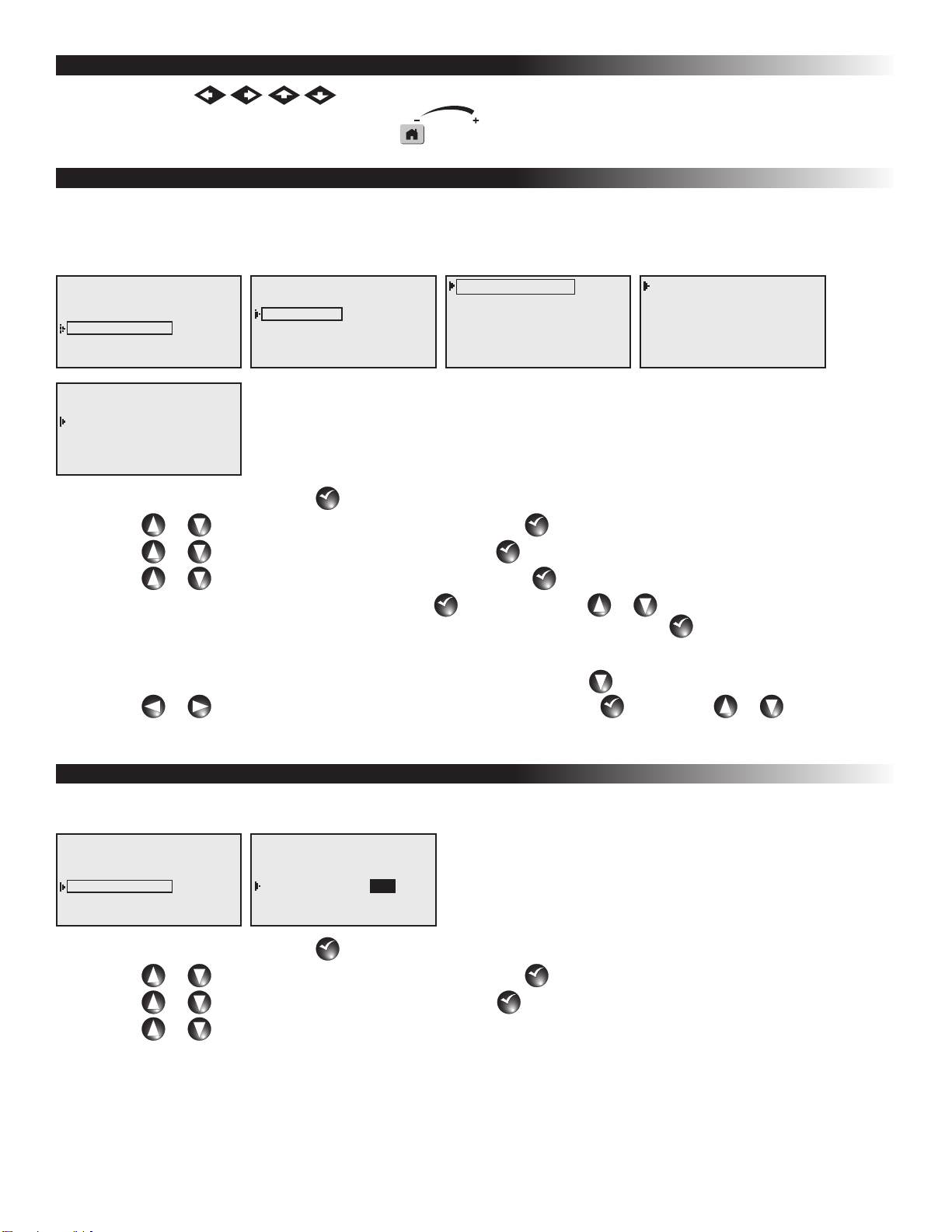
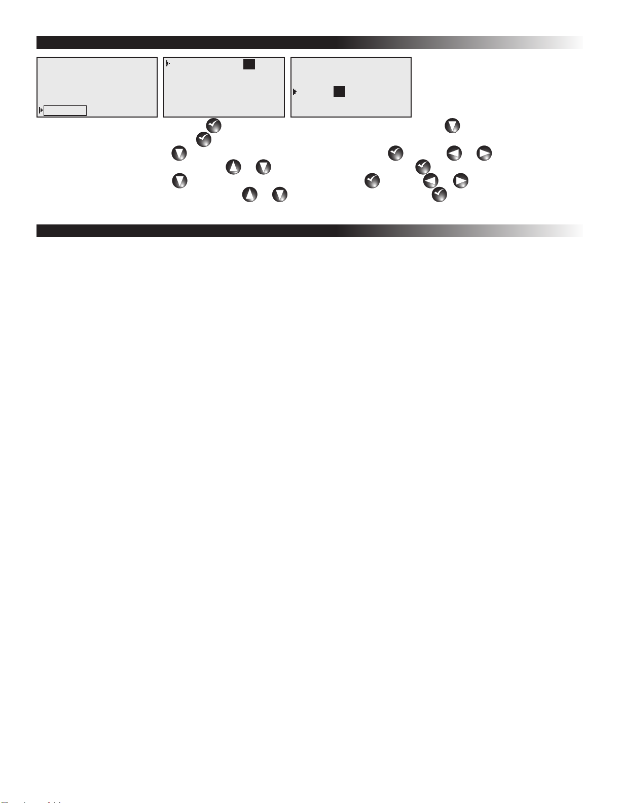
Clock Set: 11:15am
Clock Mode: Am/Pm
Date Mode: MMDDYY
Date: 01/01/16 Fri
Sat Address: 001
Max Sim Sta: 05
11
Clock Set: 11:15am
Clock Mode: Am/Pm
Date Mode: MMDDYY
Date: 01/01/16 Fri
Sat Address: 001
Max Sim Sta: 05
01
1. While at the Home Screen, press
SELECT
SELECT
to access the satellite menu selection. Press the arrow repeatedly until
Settings is selected and press
SELECT
SELECT
.
2. To set the time, press the arrow until Clock Set is selected and press
SELECT
SELECT
. Use the or arrows to navigate
between Hours and Minutes. Use the or arrows to set the values. Press
SELECT
SELECT
to nalize.
3. To set the date, press the arrow until Date is selected and press
SELECT
SELECT
. Use the or arrows to navigate
between days, months and year. Use the or arrows to set the values. Press
SELECT
SELECT
to nalize.
Satellite Operations Using a Hand-Held Radio
The following list of satellite operations can be initiated in the eld using a hand-held radio keypad. All operation
commands must begin with the following keypad sequence: * 9 followed by the 3-digit satellite address number. The
command code is then entered, followed by additional digits which represent selected stations and/or run time values.
All station numbers from 1–9 must be entered with a preceding 0; i.e., station 1 is entered as 01.
Example: Conrm communication to the satellite by issuing a manual station start command as follows: Press * 9, the
3-digit satellite address code, command code 7521 and 01 (station 1). An audible click should be heard from the station
relay and the corresponding station output LED should turn on. Visually check for sprinkler operation. To step forward
through the stations, press * 1; to step back through the stations, press * 2. To terminate the test, use command code
7520.
Command Code Operation Description
7510 Turns o individual stations; e.g., 7510 01 02 40 turns o stations 1, 2 and 40.
7511 Turns on individual stations; e.g., 7511 01 02 40 turns on stations 1, 2 and 40.
7512 Syringes individual stations for a predetermined number of 30-second intervals (already dened
in the satellite); e.g., 7512 01 02 turns on stations 1 and 2 for 30-second intervals.
7513 Disables individual stations; e.g., 7513 01 03 disables stations 1 and 3. After this command, on
and o commands will be ignored for stations 1 and 3 until the stations are re-enabled.
(See 7514.)
7514 Enables individual stations; e.g., 7514 01 03 enable stations 1 and 3.
7515 Sequentially syringes a specied station number range; e.g., 7515 10 20 will syringe stations 10
through 20 sequentially.
7516 Sequentially syringes individual stations; e.g., 7516 10 11 will syringe stations 10 and 11.
Multiple syringe groups can also be run. Enter two dashes between stations to designate
separate syringe groups; e.g., 7516 10 11 - - 22 24 26 28 will run two sequential syringes at the
same time on stations 10 and 11 and stations 22, 24, 26 and 28.
7517 Turns on individuals stations for a specied number of hours, minutes and seconds;
e.g., 7517 01 30 00 23 24 25 turns stations 23, 24 and 25 on for 1 hour, 30 minutes and no
seconds.
7518 Turns on individual stations for a specied number of minutes; e.g., 7518 10 23 24 25 turns on
stations 23, 24 and 25 for 10 minutes.
7520 Turns o a sequential station run operation (initiated by command code 7521).
7521 Turns on a sequential station run operation; e.g., 7521 01 turns on station 1. To step forward
through the stations, press * 1; to step back through the stations, press * 2.
7524 Turns on individual stations as switches; i.e., does not simultaneously energize the pump.
Note: Will not turn o the pump if already running. E.g., 7524 25 35 45 turns on stations 25, 35
and 45 without energizing the pump.
7525 Turns on individual stations as switches for a time given in minutes; i.e., does not simultaneously
energize the pump in this command string, the run time is entered rst, followed by the station
numbers; e.g., 7525 25 05 42 turns on stations 5 and 45 for 25 minutes without energizing the
pump.
7526 Turns on individual stations as switches for the time given in hours, minutes and seconds. In this
command string, the run time is entered rst, followed by the station numbers;
e.g., 7526 02 30 45 25 26 27 turns on stations 25, 26 and 27 for 2 hours, 30 minutes and 45
seconds.
7540 Turns o all stations (this satellite only).