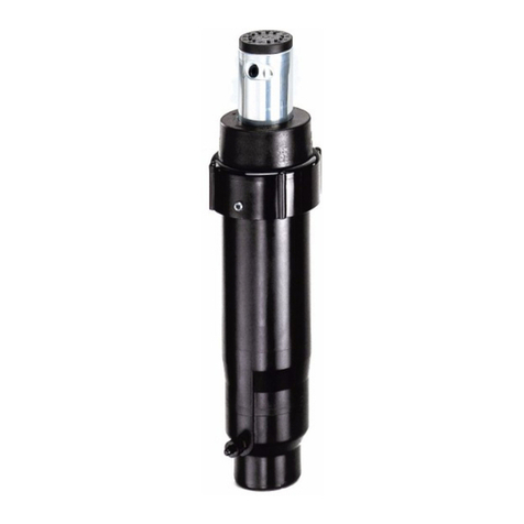
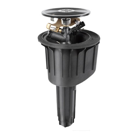
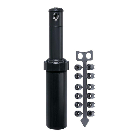
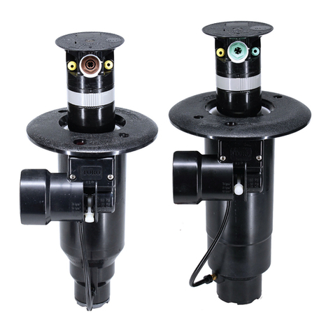
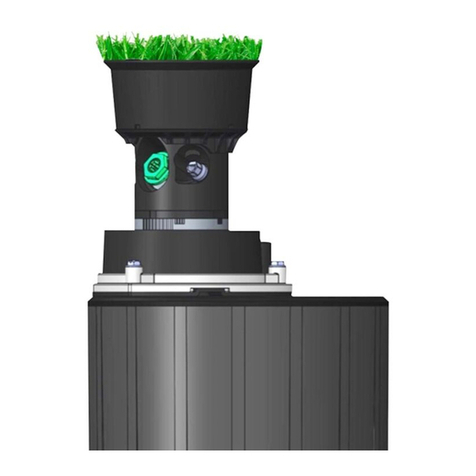
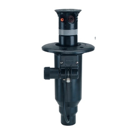
Toro TruJectory FLEX800 Series User manual

FLEX800TM Series Sprinklers
FLX55-6 – 24-Position TruJectoryTM
October, 2014
Specifications
Radius: 52’–100’ (15,8–30,5m)
Flow rate: 13.9–61.1 GPM (52,6-231
LPM)
Arc: Bidirectional, part circle rotation,
adjustable from 40-330, and true
unidirectional 360full-Circle rotation.
Pilot Valve-selectable at 50, 65, 80 or 100
psi (3,5, 4,5, 5,5 and 6,9 Bar)
Recommended operating pressure range:
65–100 psi (4,5–6,9 Bar)
Maximum pressure: 150 psi (10,3 Bar)
Minimum pressure: 40 psi (2,8 Bar)
Activation types – Electric Valve-in-Head:
-Standard Solenoid:
24 VAC, 50/60 Hz
Inrush: 0.30 A
Holding 0.20 A
-Spike Guard Solenoid:
24 VAC, 50/60 Hz
Inrush: 0.12 A
Holding 0.10 A
-Nickel-Plated Spike Guard Solenoid:
24 VAC, 50/60 Hz
Inrush: 0.12 A
Holding 0.10 A
-DC Latching Solenoid (DCLS):
Momentary low voltage pulse
-Integrated GDC Module w/DCLS:
Momentary low voltage pulse
Stator variations: 3
Inlet size: 1.5” (40mm) ACME
Body height: 11 5/8” (295mm)
Body flange diameter: 75/8 ” (194mm)
Pop-up height to nozzle: 3¼” (83mm)
Pop-up height (overall): 43/16” (106mm)
Weight:
3.61 lbs. (1,6 kg)
4.30 lbs. (2,0 kg) Integrated GDC
Module
Three inline nozzles; rotating stream
pattern
Precipitation rates:
Minimum: 0.50”/hr. (12,7mm/hr.)
Maximum: 1.00”/hr. (25,4mm/hr.)
Main nozzles: 9 (51, 52, 53, 54, 55, 56, 57,
58 and 59)
Trajectory: Adjustable from 7–30in 1
increments (24 positions)
Apex and Radius:
15
°
25
°
65psi(4,5Bar)
51
–
6’(1,8m)@51’(15,5m) 13’(4m)@54’(16,4m)
52
–
6’(1,8m)@51’(15,5m) 11’(3,4m)@64’(19,5m)
53
–
7’(2,1m)@59’(18m) 13’(4m)@68’(16,5m)
54
–
8’(2,4m)@63’(19m) 15’(4,6m)@74’(22,6m)
55
–
9’(2,7m)@66’(20m) 15’(4,6m)@76’(23m)
80psi(5,5Bar)
56
–
8’(2,4m)@75’(22,9m) 18’(5,5m)@83’(25,3m)
57
–
9’(2,7m)@74’(22,5m) 19’(5,8m)@82’(25m)
5818’(5,5m)@45’(13,7m)
5921’(6,4m)@49’(14,9m)
Bidding Specifications
The sprinkler shall be capable of full-and
part–circle operation and be a gear-driven
rotary type. The sprinkler shall include a
ratcheting riser feature that allows the user to
adjust the position of the riser in the body
without disassembly. The arc of the
sprinkler shall be adjustable by the use of an
adjustment band located between the nozzle
base and riser. The left terminus of the arc
shall be fixed, with the right position
adjustable from a 40arc minimum up to a
360arc maximum. When the 360arc
adjustment position is reached, the sprinkler
will rotate uni-directionally in the clockwise
direction. The sprinkler shall be adjustable
wet or dry, by hand, using no tools. The arc
adjustment band shall identify the 90, 180,
270and 360arc positions. The end-of-arc
dwell time shall not exceed 2 seconds and
will generally be less than 1 second.
Rotation shall be accomplished by a water-
lubricated compound cluster gear drive with
balanced reversing gear plate. The drive
assembly shall be driven by a spring-loaded,
poppet-type, variable stator, sized to provide
3-minute, full-circle rotation speeds
throughout the pressure range. The drive
and stator assemblies shall be constructed of
corrosion-proof plastic and stainless-steel
components.
The sprinkler shall include a nozzle base
clutching feature that allows the user to
rotate the nozzle base in either direction, wet
or dry, and hold it in one position during
operation to allow for spot watering.
Water distribution shall be via three nozzles
mounted in a 2¼”-diameter (57mm) plastic
nozzle turret. The three nozzles shall be
oriented in the same direction and elevate
3¼” (83mm) above the body when in
operation. All nozzles shall be of a thread-in
type accessible from the front with no other
disassembly required. All nozzles are color-
coded for easy identification of radius and
gallonage performance capabilities, and shall
be designed to allow any particle capable of
passing through the riser screen to pass
through the nozzle. The sprinkler shall be
capable of accepting a fourth nozzle that can
be installed 180from the main nozzle to
provide coverage behind the sprinkler.
This back nozzle position shall be
manufactured with a factory-installed plug
that can be removed to accept over 50
different inner and intermediate nozzle
combinations. The sprinkler shall be capable
of accepting 9 different color-coded main

FLEX800TM Series Sprinklers
FLX55-6 – 24-Position TruJectoryTM
October, 2014
nozzles and a main nozzle adapter, and 10
different color-coded inner/intermediate
nozzles. The main nozzle shall incorporate a
trajectory adjustment that provides a main
nozzle discharge angle from 7to 30in 1
increments. Trajectory adjustment shall be
capable while the sprinkler is in operation or
not. The sprinkler shall identify the
trajectory adjustment setting from the top of
the sprinkler. Close-in watering distribution
shall be achieved by an inner nozzle capable
of adjusting the distribution profile to
optimize uniformity. The cap shall identify
the installed main nozzle and the date of
manufacture.
The pilot valve assembly shall incorporate
one of five electrical activation types
(described below) to control the ON-OFF
operation of the sprinkler. It shall provide
four pressure-point selections (50, 65, 80 and
100 psi; 3,5, 4,5, 5,5 and 6,9 Bar), with a
vandal-resistant locking feature that ensures
the desired setting is maintained. The
pressure points shall be graphically illustrated
in psi and kg/cm2. The pilot valve assembly
shall include a pressure-regulation feature
that continuously monitors the operating
pressure inside the sprinkler body, making
the necessary adjustments to ensure the
desired and set regulation pressure is
maintained. The pilot valve assembly shall
incorporate a manual control feature that is
accessible from the top and allows the
sprinkler to be manually selected “ON”,
“OFF” or placed in the “AUTO” position
awaiting commands from the control device.
The manual selector shall be red in color for
enhanced visibility. The pilot valve assembly
shall be stamped with the manufactured
date.
The sprinkler shall incorporate an electrical
solenoid for activation of the integrated
control valve in one of five activation types
as described below.
Standard Solenoid
The Standard solenoid shall be suitable for
24 VAC, 50/60 Hz service with an inrush
current of 0.30 A @ 50/60 Hz, and holding
current of 0.20 A @ 50/60 Hz and shall be
capable of withstanding a voltage surge of up
to 9k volts in the common and normal
modes without failure.
Spike Guard Solenoid
The Spike Guard solenoid shall be suitable
for 24 VAC, 50/60 Hz service with an
inrush current of 0.12 A @ 50/60 Hz, and
holding current of 0.10 A @ 50/60 Hz. and
shall be capable of withstanding a voltage
surge of up to 20k volts in the common and
normal modes without failure.
Nickel-Plated Spike Guard Solenoid
The Nickel-Plated Spike Guard solenoid
shall be suitable for 24 VAC, 50/60 Hz
service with inrush current of 0.12 A @
50/60 Hz, and holding current of 0.10 A @
50/60 Hz. and shall be capable of
withstanding a voltage surge of up to 20k
volts in the common and normal modes
without failure. It shall also have a nickel-
plated core to provide additional corrosion-
resistance in potable and non-potable water
applications.
DC Latching Solenoid
The DC latching solenoid shall be activated
by a momentary low-voltage pulse that
moves the plunger from the “OFF” to the
“ON” position where it is maintained by a
permanent magnet in the solenoid. To
deactivate, a second momentary low-volt
pulse is applied to move the plunger from
the “ON” position to the “OFF” position.
This activation type is generally used with a
GDC module that is remotely located.
Integrated GDC Module
The Integrated GDC Module activation
type incorporates the GDC module attached
to the outside of the sprinkler body and
includes a DC latching solenoid for
activation of the control valve. The DC
latching solenoid shall be activated by the
Integrated GDC module with a momentary
low voltage pulse that moves the plunger
from the “OFF” position to the “ON”
position where it is maintained by a
permanent magnet in the solenoid. To
deactivate, a second momentary low-volt
pulse is applied to move the plunger from
the “ON” position to the “OFF” position.
The internal valve assembly shall be a
piston-type that vents to the atmosphere,
providing valve friction loss of less than 5
psi (0,34 Bar). The sprinkler shall be
designed to provide smooth valve closure in
excess of two seconds to minimize damage
resulting from surges and water hammer. All
valve seals shall be constructed of natural
rubber. The valve seat seal shall be
constructed of fabric-reinforced natural
rubber. The electric valve assembly shall
incorporate a 100-mesh stainless-steel screen
for the control water, preventing entry of
foreign materials into the pilot valve
assembly.
The sprinkler body and cap shall be
injection-molded from ABS – a corrosion-
proof, impact-resistant, UV-resistant, heavy-
duty, engineering-grade plastic material. The
cap and nozzle base shall incorporate a pull-
up feature that provides improved
serviceability of nozzles and riser. The
sprinkler shall have two plastic filter screens
– a top-serviceable coarse rock screen in the
body inlet sized to prevent entry of larger
foreign material from entering the body, and
a finer screen threaded into the riser, sized to
prevent foreign material from clogging the
nozzle.
The sprinkler shall have a riser/body seal
assembly that regulates flushing during pop-
up and retraction to clear any debris from
around the riser, and a heavy-duty, stainless-
steel spring to ensure positive retraction.
The riser is sealed by a durable, over-molded
urethane ring on the seal retainer. Sprinkler
flush rate shall not exceed 5 GPM (18,9
LPM).
The sprinkler shall be capable of identifying
the use of effluent water via a lavender-
colored marking. The sprinkler cap shall
indicate model designation, nozzle number
and manufacturing date code.
The sprinkler shall be of a pop-up design
with an overall height of 11 5/8” (295mm), a
body flange diameter of 75/8 ” (194mm), a
cap diameter of 35/8 ” (92mm) and a pop-up
stroke of 4 3/16” (106mm). The sprinkler
shall have a 1½” (40mm) ACME female-
threaded inlet. The sprinkler shall be capable
of covering ___ feet radius at ___ pounds
per square inch pressure with a discharge
rate of ___ gallons per minute.
The sprinkler shall be developed and
manufactured by an ISO 9001-certified
facility. The sprinkler shall be model
number __________ and shall be
manufactured by The Toro Company,
Irrigation Division.
FLEX800TM Series Sprinklers
FLX55-6 – 24-Position TruJectoryTM
October, 2014
Recommended Installation Procedures
The FLX55-6 sprinkler is designed
specifically for turf areas requiring _____
coverage. These products offer the most
economical method of irrigation where flows
and system pressures are available to support
a greater radius.
The FLX55-6 sprinklers should be
specified for installation on a Toro swing
joint. The swing joint should be specified as
a triple-swing type, allowing movement up,
down, laterally and at an angle-to-grade. The
sprinkler should be installed with the body
cover at grade.
Individual sprinkler head control is
accomplished using a single FLX55-6 valve-
in-head sprinkler per controller station. Use
of the valve-in-head model will allow
individual station control, and is particularly
useful for irrigating distinct turf regions at
unique application rates.
FLX55-6 sprinklers are engineered to
provide a smooth, consistent curtain of
water across the arc, with provision made for
head-to-head coverage. For proper spacing,
ensure that system design and installation
accounts for prevailing wind conditions and
body cover angle-to-grade.
It is recommended that sprinklers are
installed 2” (5cm) from hardscaping and 6”-
12” (15,2-30,5cm) from buildings or other
vertical impediments to allow for normal
maintenance procedures and to minimize
overspray on buildings. Where possible,
sprinkler heads should be installed in a
manner that will minimize nozzle stream
contact with trees, controller enclosures,
shrubbery or other obstructions.
This manual suits for next models
1
Other Toro Irrigation System manuals

Toro
Toro XP300-02 Quick guide

Toro
Toro T5 Series User manual

Toro
Toro OSMAC E-SERIES User manual

Toro
Toro P2 Series User manual

Toro
Toro Super 800 Series User manual

Toro
Toro MultiStream 53246 User manual

Toro
Toro ZSERIES 570Z User manual

Toro
Toro TR70XT SERIES Manual

Toro
Toro TS120 User manual

Toro
Toro EVOLUTION Series User manual

Toro
Toro IMPACT 53721 User manual

Toro
Toro NO FOUND TMC-424E User manual

Toro
Toro 690 Series User manual

Toro
Toro 570Z PRX Series User manual

Toro
Toro TR50 Manual

Toro
Toro INFINITY Series User manual

Toro
Toro 570Z User manual

Toro
Toro 340 Series User manual

Toro
Toro 53765 - Outdoor Ecxtra Sprinkler Timer User manual

Toro
Toro 2001 Series User manual