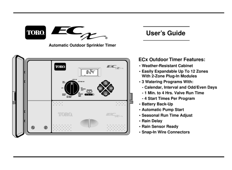
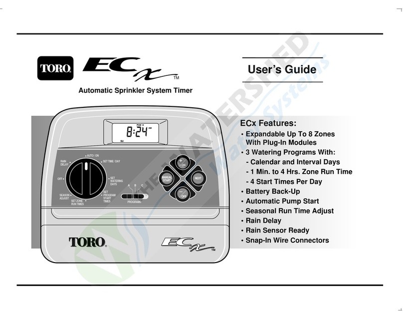
Toro 09501 User manual

OPERATOR'S
MANUAL
FORM NO. 3318-400 GB Rev A
MODEL NO. 09501—60001 & OVER
®FAIRWAY AERATOR
© 1996,TheToro Company

Foreword
The Fairway Aerator has advanced concepts in engineering and design, and if properly maintained, will provide excellent
service.
This manual emphasizes safety, mechanical and general product information. DANGER, WARNING and CAUTION
identify safety messages. Whenever the triangular safety alert symbol appears, understand the safety message that fol-
lows. Read the safety instructions beginning on page 3. IMPORTANT highlights special mechanical information and
NOTE emphasizes general product information worthy of special attention.
If help concerning operation, maintenance or safety is ever needed, contact the local authorized TORO Distributor. In
addition to genuine TORO replacement parts, the distributor also has optional equipment for the complete line of TORO
turf care equipment. Keep your TORO all TORO. Buy genuine TORO replacement parts and accessories.
Table of Contents
Safety Instructions 3
Safety Symbol Glossary 5
Specifications 7
Before Operating 8
Adjusting Tine Penetration 9
Check Reservoir and Gear Case Oil Levels 9
Timing the Aerator to the Tractor 9
Operation 13
Training Period 13
Before Aerating 13
Aerating Procedures 13
Transport Operation 13
Inspection and Clean-up After Use 14
Changing Tine Configuration 14
Stomper Assemblies 14
Operating Tips 15
Lubrication 15
Maintenance 18
2

3
Awareness, concern and proper training of personnel
involved in operation, maintenance and storage of this
machine are vital to your safety. Improper machine use
or maintenance can result in injury or death. To reduce
potential for injury or death, comply with all safety
instructions.
BEFORE OPERATING
1. Read and understand this guide thoroughly before
operating the machine. Become familiar with all
controls and know how to stop quickly. Only
trained operators, skilled in slope operation who
have read this guide should operate this machine.
2. Never allow children to operate the machine or
adults to operate it without proper instructions.
3. Remove debris or objects that might interfere with
operation. Keep bystanders away from the work
area.
4. Keep all shields, grass deflectors and safety devices
in place. If a shield or safety device is damaged or
malfunctioning, or a decal is illegible, repair or
replace it before operating the machine. Be sure all
nuts, bolts and screws are tight to assure the
machine is in safe operating condition.
5. Do not operate the machine while wearing sandals,
tennis shoes, sneakers or shorts. Do not wear loose
fitting clothing that could catch in moving parts.
Always wear long pants and substantial shoes.
Wearing safety glasses, safety shoes, ear protection
and a helmet is advisable.
While Operating
6. Using the machine demands attention. To prevent
loss of control:
A. Use only in daylight or when there is good
artificial light.
B. Watch for holes or other hidden hazards.
C. Do not transport the machine close to sand
traps, ditches, creeks or other hazards.
D. Reduce speed on side hills and before making
sharp turns to prevent tipping or loss of con-
trol.
E. Look behind the aerator before backing up.
7. If the tines strike a solid object or the machine
vibrates abnormally, raise the coring head, disen-
gage power to the aerator, stop the prime mover
and engage the parking brake before leaving the
operator’s position. Lift the safety/transport stands
to their full upright position and lower the coring
head onto the stands. Stop the engine and disen-
gage power to the aerator before making repairs or
adjustments.
Inspect the coring head and other machine parts for
damaged or malfunctioning parts and repair or
replace before resuming operation. Be sure all
parts are in good condition and all fasteners are
tight.
8. Before leaving the machine unattended, raise the
coring head, disengage power to the aerator and set
the parking brake. Lift safety/transport stands to
full upright position and lower the coring head onto
stands. Stop the engine.
9. Never dismount while the prime mover is in
motion. Never get on or off the prime mover while
the engine is running and the PTO is engaged.
Never step over the PTO shaft to reach the other
side of the aerator—walk around the machine.
10. Before transporting the machine from one area to
another, raise the coring head, stop the prime
mover, shift into neutral and engage the parking
brake. Lift the safety/transport stands to their full
upright position and lower the coring head onto the
stands.
Safety Instructions
4
Maintenance
11. Before servicing the machine, raise the coring
head, disengage power to the aerator, shift the
prime mover to neutral and set the parking brake.
Lift the safety/transport stands to their full upright
position and lower the coring head onto the stands.
Stop the engine. Disconnect the PTO shaft and
hydraulic hose connection.
12. Make sure the machine is in safe operating condi-
tion. Keep nuts, bolts and screws tight. Check the
tine mounting nuts and bolts frequently to ensure
they are tightened to specification.
13. Before applying hydraulic pressure to the system,
be sure all hydraulic line connectors are tight and
hydraulic hoses and lines are in good condition.
14. Keep your body and hands away from pin hole
leaks or nozzles that eject hydraulic fluid under
high pressure. Use paper or cardboard, not your
hands, to search for leaks. Hydraulic fluid escap-
ing under pressure can have sufficient force to pen-
etrate your skin and do serious damage. If fluid is
injected into your skin, it must be removed within a
few hours by a doctor familiar with this form of
injury or gangrene may result.

5
SAFETY ALERT
SYMBOL GENERAL HAZARD
SAFETY ALERT CRUSHING OF
WHOLE BODY,
APPLIED FROM
ABOVE
CRUSHING OF
FINGERS OR HAND,
FORCE APPLIED
FROM SIDE
CUTTING OF
FINGERS OR HAND CUTTING OF FOOT CRUSHING OR
PUNCTURE OF FOOT,
CORING HEAD
WHOLE BODY ENTANGLEMENT,
IMPLEMENT INPUT DRIVE LINE FINGERS OR HAND
ENTANGLEMENT,
CHAIN DRIVE
THROWN OR FLYING
OBJECTS, WHOLE
BODY EXPOSURE
RUNOVER/BACKOVER,
GREENS AERATOR RUNOVER/BACKOVER,
HC 4000 AERATOR SECURE LIFTING CYLINDER WITH
LOCKING DEVICE BEFORE
GETTING IN HAZARDOUS AREA
INSERT SAFETY LOCK
BEFORE GETTING IN
HAZARDOUS AREA
STAY A SAFE DISTANCE FROM MACHINE,
GREENS AERATOR STAY A SAFE DISTANCE FROM MACHINE,
HC 4000 AERATOR
STAY CLEAR OF ARTICULATION
AREA WHILE ENFINE IS RUNNING,
GREENS AERATOR
DO NOT OPEN OR REMOVE
SAFETY SHIELDS WHILE
ENGINE IS RUNNING
SHUT OFF ENGINE & REMOVE
KEY BEFORE LEAVING OPERATOR
POSITION, GREENS AERATOR
CONSULT TECHNICAL MANUAL
FOR PROPER SERVICE
PROCEDURES
READ OPERATOR’S
MANUAL HEARING PROTECTION
MUST BE WORN BRAKE SYSTEM ENGAGE DISENGAGE
Symbol Glossary

P
1 INCH (25mm)
P
ON/START OFF/STOP FAST SLOW CONTINUOUS
VARIABLE,
LINEAR
ENGINE START ENGINE STOP
PARK UNLEADED FUEL FUEL TANK FILL
LINE LOCK UNLOCK CORING HEAD
ALWAYS HAVE CORING H
E
FULLY UP FOR TRANSPO
R
FULLY DOWN FOR CORIN
G
TRACTION DRIVE MANUAL CHOCK WHEELS IN PARKED POSITION,
ALWAYS PARK ON LEVEL SURFACE,
FAIRWAY AERATOR
ALWAYS FORK FROM FRONT OR REAR
OF MACHINE, HC 4000 AERATOR LEVER OPERATION
6

7
Types: Three-wheel, PTO-driven, tow-behind deep cor-
ing turf/fairway aerator.
Tractor Requirements: 26–33.6 kw (35–45 hp) @
standard power take-off speeds.
Travel Speed: 2.93–5 km/hr (1.8–2.2 mph).
Maximum PTO Speed: 540 rpm.
Maximum Top Crankshaft Speed: 400 rpm.
Construction:
Frame—Welded tubular and structural steel.Coring
Head—Welded structural steel bar and plate.
Hitch—Five 89 mm (3 1/2 in.) spacings for various
hitch-to-PTO configurations.
Ball Coupler: SAE Class 2, bolt-on for 76 mm (3 in.)
channel. 1587 kg (3500 lb) GVW for 51 mm (2 in.)
ball.
Ball: 51 mm (2 in.) forged ball with 51 mm (2 in.) long
shank, 1 inch 14 UNEF thread. SAE Class 3, 2268 kg
(3500 lb) GVW.
Tires: Front—18 x 9.50-8 (4 PR) tubeless.Rear—23 x
8.50-12 (4 PR) tubeless.
Drive Lines:
Front—Ag-type 35R series with plastic safety shield,
quik-loc on the tractor end, ball-shear device on imple-
ment end. Operating stroke from center of bearing
crosses: 92 cm (36-1/4 in.) collapsed minimum to 127
cm (50 in.) extended maximum.
Rear—Ag-type 14R series with plastic safety shield.
Quik-loc on both ends.
Gear Cases: PTO shaft-driven front gear case with spur
type gears, a right angle gear case with bevel gears and
three individual, integral spur gear cases. Integral gear
cases lubricated by structural tube reservoir. Reservoir
level checked by dipstick in fill port.
Lift Cylinder: Single-acting cylinder. Uses tractor
hydraulics to lower and raise the coring head.
Hydraulic Hose: 9.5 mm x 304.8 cm (3/8 x 120 in.), SAE
100R1A.
Quick Coupler: 1/2 - 14 FE NPT ends. Meets ISO, SAE,
ASAE, interchangeability requirements.
Hose Stand: Adjusts from 112 - 138 cm (44 - 54 1/2 in.) at
three 89 mm (3 1/2 in.) increments (ground to center of hose
holder).
Safety/Transport Stands: Swing-up type. Prevents acci-
dental lowering of the coring head during service and/or turf
guard conversion. Also used to lock unit up during trans-
port.
Turf Guards: Three; each semi-rigid mounted with com-
pression spring flotation and front mounted rollers.
Rollers: Three each (one per turf guard) mounted indepen-
dently to front of each turf guard. 11.4 cm (4 1/2 in.) diam-
eter; 27.9 cm (11 in.) long (flat portion).
Covers: Minimum of 4.76 mm (3/16 in.) thick. Black
semi-gloss, fiberglass reinforced resin. Secured to unit by
flexible draw latches.
PTO Drive line Shield:On front gear case. Shields the
PTO drive line. Can be tipped up for drive line service.
Coring Capacity (theoretical) @ 3.5 km/hr (2.2 mph):
Assumes no reduction in total area due to overlap, turning,
stops, etc.
Coring Patterns:
2 Tines/Head, 7/8 in. Tines—Effective Coring Width—160
cm (63 in.).Total Tines—1 row = 12 tines.Hole Pattern—
13.3 x 15.2 cm (5 1/4 x 6 in.); 2 tines.Depth—To 12.7 cm (5
in.).*Sp m/hr (Sq ft/hr)—5665 sq m/hr (60,984 sq
ft/hr).*Hectares/hr (Acres/hr)—0.567 ha/hr (1.4 acres/hr).
6 Tines/Head, 3/4 in. Tines—Effective Coring Width—160
cm (63 in.).Total Tines—2 rows of 18 = 36 tines.Hole
Pattern—8.9 x 7.6 cm (3 1/2 x 3 in.); 6 tines.Depth—To 7.6
cm (3 in.).*Sp m/hr (Sq ft/hr)—5665 sq m/hr (60,984 sq
ft/hr).*Hectares/hr (Acres/hr)—0.567 ha/hr (1.4 acres/hr).*
with optional 30/40 teeth gear set.
Specifications

Dimensions: Length—279.4 cm (110 in.).Width—228.6 cm
(90 in.) [from outside of tires].Height—11.8 cm (44
in.).Weight—1350 kg (2975 lb).Wheel Base—113.03 cm (44
1/2 in.) with 10.8 cm (4 1/4 in.) rearward castor.
Standard Equipment: Equipped with either two 7/8 in. or six
3/4 in. tine turf guards (tines not installed) with other configura-
tion included loose. Included with two 35-tooth gears in front
gear case are 32, 33, 34, 36, 37 and 38 tooth gears to match the
aerator to user’s tractor. Six shear pin sets (bolts & nuts), a 51
mm (2 in.) No. 3 forged hitch ball and female half of quick cou-
pler (1/2–14 FE NPT) are also supplied.
8

Figure 1
1. Height Adjuster
2. Height adjuster mounting capscrews & flatwasher.
Figure 2
1. Right-angle gear case
2. Gear case fill plug
Figure 3
1. Fill plug dipstick
2. Oil level between marks
3. Reservoir fill hole
9
AdjustingTine Penetration
To adjust equally on both sides:
1. Loosen the capscrews securing both height adjusters
(Fig. 1). Raise the adjusters until the bolt bottoms out in
the slot.
2. Maximum penetration depth of 12.7 cm (5 in.) for 7/8
in. (2 tine) and 7.6 cm (3 in.) for 3/4 in. (6 tine) config-
uration. To adjust for less penetration, lower the height
adjusters.
3. After adjusting to the desired depth setting, tighten the
mounting capscrews to secure the adjustment. Adjust
the height adjuster on the opposite side to the same set-
ting.
Check the Reservoir & Gear Case
Oil Levels
1. With machine on level surface, remove the oil fill/dip-
stick plug from the right-angle gear case (Fig. 2).
2. The oil level should reach the mark on the dipstick. If
oil is needed, add SAE EP 90W gear oil. Install the fill
plug.
3. At the rear of the machine, remove the dipstick assem-
bly from the reservoir. The oil level should be between
the marks on the dipstick (Fig. 3). If oil is needed, add
SAE EP 90W gear oil. Replace the gear case cover.
TimingThe AeratorToTheTractor
To operate the aerator correctly, set the tractor as follows:
1. There must be 540 PTO rpm at normal engine operating
speed.
2. With the PTO operating at 540 rpm, select a transmis-
sion gear that allows the tractor to operate 30.5 m (100
ft) within 30–38 seconds; i.e., 2.9–3.5 km/hr (1.8–2.2
mph).
Before Operating
2
1
1
3
2

Figure 4
1. Pick-off gear case
2. Gear case fill plug
Figure 5
1. Oil level to center of shafts
2. Driver gear
3. Driven gear
4. Lynch pin
Figure 6
Tractor Hitch Requirements (Preferred)
A = 14” = End of PTO to hitch pin hole
B = 1” = Horizontal distance from hitch pin to tire
C = 15” = Height of hitch
D = 8” Top of hitch to center line of PTO
E = 4” = Auxiliary hole spacing (not required)
F = .81” diameter =Hitch pin hole (minimum)
G = .68” diameter = Auxiliary hole (not required)
To set the tractor:
1. On a test area, measure and mark off 30.5 m (100 ft).
2. Operate the tractor engine to attain 540 PTO rpm. Select a
transmission gear and operate the tractor (with or without
the aerator) over the test area. Record the time it takes to
travel 30.5 m (100 ft).
Note: If your tractor doesn’t have a tachometer, measure
the PTO shaft rpm with a hand tachometer.
3. Make three passes, record the time for each pass, and calcu-
late the average time needed to travel 30.5 m (100 ft). If
the average is not within 30–38 seconds, select another
transmission gear and recheck until the average time meets
the recommended time limits.
Important: Use only established tractor settings when
operating the aerator. Never operate the aerator with
the tractor in any other gear setting.
To prepare the aerator:
Install proper timing gears in the aerator pick-off gear case. Use
the chart on the next page for gear selection.
10
2
1
3
1
4
2

Important: Driver and driven gears selected must combine
to add up to 70.
Gear Installation:
1. Remove the pick-off gear case cover (Fig. 4).
2. Remove the lynch pins securing the driver and driven gears
and slide the gears off the shafts (Fig. 5).
3. Install the driver and driven gears matching the chart time
and secure with lynch pins (Fig. 5).
Note: The number of gear teeth is stamped on each gear.
4. Install the gear case cover. Make sure the machine covers
are in place and verify the aerator/tractor timing.
VerifyingTiming:
1. Raise the coring head, set the parking brake, stop engine
and lower the coring head supports (Fig. 7).
2. With the tractor at proper settings, operate the aerator a
short distance, then raise the coring head, disengage the
PTO and stop the tractor. Set the parking brake, lower the
coring head onto supports (Fig. 7) and stop the engine.
11
GEARS
Sec./30.5 m Driver Driven
INCREASING HOLE
SPACING 42.3 30 40
39.9 31 39
37.7 32 38
Optimum vehicle speed 35.5 33 37
(Bold Print)) 33.6 34 36
31.7 35 35
DECREASING HOLE
SPACING 30.0 36 34
28.3 37 33
26.7 38 32
25.2 39 31
23.8 40 30

Figure 7
1. Coring head support (2)
Important: Never exceed 540 tractor PTO rpm or you
may damage the aerator.
3. In the direction of travel, measure the distance between tine
holes (one tine stroke hole to another). The distance should
be:
7/8 in. tines–14.6 to 15.2 mm (5-3/4 to 6 in.).
3/4 in. tines–7.3 to 7.62 mm (2-7/8 to 3 in.).
Note: Turf hold condition can also show how well the trac-
tor and the aerator match. If the rear of the tine holes are
torn, the tractor is too slow. By contrast, if front of the tine
holes are torn, the tractor speed is too fact.
4. If the hole spacing is short (coring speed too fast), increase
spacing: replace driver gear with gear having less teeth and
driven gear with gear having more teeth (Fig. 6). If the
hole spacing is long (coring speed too slow), increase the
driver gear teeth and decrease driven gear teeth quantities;
see the gear selection chart.
5. Operate the machine and repeat steps 1–4.
IMPORTANT: Timing can sometimes by fine tuned by
gradually regulating the tractor’s tire pressure. Lowering
tire pressure provides closer spacing and raising tire pres-
sure will increase the spacing.
CAUTION: Do not exceed the maximum or minimum inflation
pressures as recommended by the tire manufacturer.
12
1

tractor and aerator components and the drive line is not
compressed below 92 cm (36 1/4 in.), nor extended over
127 cm (50 in.). Otherwise, the hitch hose or drive line
could be damaged.
Look behind frequently to be sure the machine is operat-
ing properly and is aligned with previous passes.
Should the drive line ratchet during operation:
1. Raise the coring head, disengage the PTO, and stop
immediately.
2. Set the parking brake, raise the coring head stands
and lower the head on to the stands.
3. Inspect the turf to determine the reason for the
ratcheting or tine breakage. Locate where the prob-
lem occurred and insert a non-conductive probe
into the aerator holes. If foreign material beneath
the turf caused the damage, mark the location so
the material can be either removed or avoided in
the future. If the ratcheting occurred because turf
was too hard to penetrate, raise the depth of pene-
tration and try aerating the area again. Be sure all
machine damage has been corrected before resum-
ing operation; refer to step 5.
4. Always clear the area of all damaged machine
parts, such as broken tines, etc., to prevent their
being picked up by mowers or other turf mainte-
nance equipment.
5. Replace broken tines, and inspect and correct dam-
age to those still useable. Repair any other
machine damage before commencing operation.
Transport Operation
To transport, raise the coring head, disengage the PTO
and set the parking brake. Raise the coring head support
stands and lower the coring head onto them. Climb
steep inclines slowly. Approach rough areas at reduced
speed and cross severe undulations carefully to avoid
loss of control. During sharp turns, make sure the rear
tractor tires do not contact the aerator hitch assembly.
Training Period
Before first using the aerator, use a clear area to practice
operation. Operate the tractor at the recommended PTO
speeds and gear settings and become thoroughly familiar
with the machine’s handling. Stop, start, raise and lower
the coring head, disengage the PTO and align the
machine with previous passes. Practice builds confi-
dence in the Fairway Aerator’s performance and helps
ensure proper operating techniques wherever the machine
is operated.
Before Aerating
To avoid damage, adjust the hydraulic hose extension
stand so the hose clears the tractor and the aerator’.
Inspect the operating area for hazards that could damage
the aerator and either remove them or plan how to avoid
them (flags identifying sprinkler heads, distance markets,
etc.). Carry replacement shearbolts, the tines and tools to
repair damage should the tines contact foreign materials.
Aerating Procedures
Before operating, stop the tractor, raise the coring head
and set the parking brake. Leave the tractor seat and
lower each coring head support stand. Return to seat, set
the PTO to 540 rpm, select proper gear, release the park-
ing brake and begin operation. When the tractor reaches
2.9 to 3.5 km/hr (1.8 to 2.2 mph), lower the coring head.
Although the aerator can be operated in slight curves,
operate it in a straight line for best results. If the machine
must be sharply turned, raise the coring head and disen-
gage the PTO or severe turf damage will result and the
machine may be damaged. When turning, be sure the
tractor tires clear the hitch, the hydraulic hose clears the
13
Operation
To avoid personal injury, never leave the tractor seat
without setting the parking brake and disengaging the
PTO. Never make repairs or adjustments without first
supporting the coring head on support stands. Be sure
to secure all safety devices in their correct place before
resuming operation.
CAUTION

Figure 8
1. Locknuts
2. Finger plate
Figure 9
1. Locknuts
2. Rear tine blocks
3. Front tine blocks
4. Stomper assembly
IMPORTANT: Do not exceed transport speeds of 24 km/hr
(15 mph) or the tires may fail.
Inspection and Clean-up After Use
After use, thoroughly wash the machine with a garden hose
without a nozzle to avoid seal contamination and bearing dam-
age from excessive pressure. Use a brush to remove caked
material and a mild detergent to clean the covers. Periodically
wax the cover with auto wax to keep its glossy finish. Inspect
the machine for damage, gear for oil leaks and component and
tine wear after cleaning.
ChangingTheTine Configuration
To change the tine configuration:
1. Lift the coring head, disengage the PTO and set the parking
brake. Raise each coring head support and lower the coring
head onto the supports (Fig. 7). Remove the coring head
cover and disconnect the gearbox drive line.
2. Remove the locknuts (4) securing each finger plate assem-
bly and remove the assemblies (Fig. 8).
3. Remove the tine mounting locknuts and remove the tines
(Fig. 3). Remove the rear tine blocks and slide the front
tine blocks and studs out of the stomper assembly (Fig. 9).
Note: Manually rotate the right angle gearbox shaft so the
stomper assemblies are positioned to allow removal of the
front tine block.
4. Install replacement tine blocks and the tines and tighten the
locknuts to secure the tines.
5. Mount the proper turf guard assemblies and tighten the
locknuts.
6. Connect the gearbox drive line and install the coring head
cover.
Stomper Assemblies
IMPORTANT: Within the first five (5) operating hours and
every 25 hours operation after that, you must check the
stomper assemblies for excessive lateral play. Without this
14
1
4
2
3
1
2

Figure 11
Figure 12
Figure 13
check, major component failure may result. Do not operate
the aerator until a mechanic has completed this process.
OperatingTips
1. Gradually engage the PTO at low engine speed and throttle
up to 540 RPM before lowering the coring head.
2. Make very gradual turns when aerating. Never make sharp
turns with the PTO engaged.
3. If the tractor stalls or slows too much when operating on
hard ground or when going uphill, raise the coring head
slightly until you regain speed, then lower the head again.
4. Do not aerate if the ground is too hard or dry. Best results
are obtained after a rain or when the turf has been watered
the previous day.
5. Raise the coring head penetration if the ground is hard
packed. Clean cores and aerate again at deeper penetration,
preferably after watering.
Machine Lubrication
Use No. 2 Lithium base grease on all fittings. Lubricate at times
listed or more frequently, if needed. For best results, use a hand
grease gun. Do not apply excess pressure or seals may be per-
manently damaged. To access the center drive line grease fit-
tings, disconnect one end.
NOTE: Lubricate the machine after washing it.
Figure10
15

Figure 16
Figure 17
1. Fill plug and dipstick
2. Oil level between marks
3. Reservoir fill hole
Figure 14
Figure 15
Check the Reservoir Level
After every25 hours of operation, or seasonally, whichever
comes first, check the level of in the reservoir.
1. With the machine on a level surface, remove the oil fill plug
and dipstick assembly from the reservoir (Fig 17).
2. The oil level should be between the two marks on the dip-
stick. If the oil level is not between the dipstick marks, add
SAE EP 90W gear oil until the oil level is correct.
NOTE: Under normal conditions, the reservoir oil level should
not drop. If the oil level is low, check for signs of leakage and
correct , as necessary. Should a major failure of the gearbox
components occur, drain the gear oil, flush the reservoir and
install fresh oil. The reservoir oil drain plug is located at the
lower left side of the reservoir (Fig. 18). To refill the reservoir to
16
1
3
2

Figure 18
1. Reservoir Drain Plug
Figure 19
1. Right-angle gear case
2. Gear case fill plug
Figure 20
1. Pick-off gear case
2. Gear case cover
operating level, add approximately 9 liters.
NOTE: Drain plugs are also at the bottom of each (3) gear case.
Check the Right-Angle Gear Case Oil
Level
After every 25 hours of operation, or seasonally, whichever
comes first, check the level in the right-angle gear case (Fig. 19)
1. With the machine on a levels surface, remove the oil fill
plug.
2. Add SAE EP 90W gear oil, if needed and install the fill
plug.
NOTE: Gear capacity is 750 ml.
Check the Pick-off Gear Case Oil
Level
After every25 hours of operation, or seasonally, whichever
comes first, check the level in the pick-off gear case.
1. With the machine on a levels surface, remove the gear case
cover (Fig 20).
2. The oil level should be to the center of the gear shafts
(Fig. 21). If the level is low, add SAE EP 90W gear oil and
install the cover.
NOTE: Should major failure of the pick-off gear case compo-
nents occur, the gear oil will be contaminated and should be
drained. Flush the gear case and add fresh oil. The gear case oil
drain plug is at the lower left rear side of the case (Fig. 22).
Gear case capacity is 5.5 liters.
17
1
2

Figure 21
1. Oil level to center of shafts
2. Input shaft
3. Output shaft
4. Driver gear
5. Driven gear
Figure 22
1. Gear case drain plug
Figure 23
1. Stomper assembly
2. Move laterally—both directions
Checking Stomper Assemblies
Within the first five hours of initial machine operation, and after
every 25 hours of operation thereafter, all stomper assemblies
must be checked for excessive lateral play. This must be done or
major machine component failure may result.
1. Grasp each stomper assembly at the bottom and try to move
the assembly laterally in each direction (Fig 23). Do not
move fore and aft. There should be little or no movement
of the assembly. If there is movement, go to step 2. If there
is little or no movement, check the next assembly.
2. Remove the roll pin securing the castle nut to the top crank-
shaft (Fig. 21). Check the castle nut for tightness with your
fingers. If the nut is very loose, turn it clockwise until it is
flush against the outer spacer and you feel resistance
(Fig. 24).
3. Using a torque wrench, turn the nut clockwise (to tighten)
until a slot in the nut aligns with the shaft hole. Do not
exceed 54 Nm. Install the roll pin.
NOTE: The shaft is cross drilled, so only 1/12 turn (max)
should be needed to align the roll pin hole.
General Maintenance
After each use of the machine and after clean up, do the follow-
ing:
1. Examine the tines for damage and sharpness and repair or
replace, as necessary.
2. Inspect for signs of leakage, excessive component wear or
component damage. Repair or replace, as necessary.
3. Thoroughly wash the machine with a garden hose without a
nozzle so that contamination and seal and bearing damage
from water pressure will be avoided. A brush may be used
to remove caked-on material. Use mild detergent to clean
the covers. Applying a coat of auto wax periodically will
retain the cover’s glossy finish. After cleaning, inspect for
machine damage, gear oil leakage, component and tine
wear.
18
Maintenance
1
4
2
3
1
2

Figure 24
1. Roll pin
2. Castle nut
3. Top crank
4. Outer spacer
Aerator Gear CaseTimingTips
If disassembly of the aerator drive system is required for mainte-
nance, the unit will need to be retimed to ensure n balance, equal
loading of the tine arms and optimum hole quality. There are
two separate procedures to properly tine the aerator gear cases.
Use the following tips for each procedure when reassembling the
gear case.
Timing the upper and lower crank shafts on each
individual gear case
1. The upper and lower crankshaft flywheels for each tine arm
must be assembled so the offset shafts are located in the
same “clock” position. If the upper offset shaft is posi-
tioned at 12 o’clock, then the lower offset shaft must be at
the 12 o’clock position.
2. To achieve the proper position for each gear case, install the
timing bar (supplied with the machine) to the upper and
lower crankshaft by aligning each roll pin and securing the
socket head capscrew.
Synchronizing the Gear Cases
1. The tine arms are numbered 1 to 6 from left to right, as
viewed from the rear of the machine. Each of the three
gear cases must be connected to each other in a proper
phase to ensure that only one set of tines will enter the turf
at a time.
2. Rotate the number 1 tine arm to the lowest position as a
starting point. When viewed from the left side of the coring
head, the stamped numbers 2, 3, and 1 should be visible at
the top of the first, third and fifth upper crank, respectively.
19
1
24
4

Table of contents
Other Toro Lawn And Garden Equipment manuals

Toro
Toro TRX-20 User manual

Toro
Toro 04476 User manual

Toro
Toro 38365 User manual

Toro
Toro 136-3860 User manual

Toro
Toro Ultra Sonic Boom 41219 User manual

Toro
Toro VS-70 User manual

Toro
Toro 09830 User manual

Toro
Toro procore sr54 User manual

Toro
Toro ProCore 864 User manual

Toro
Toro Greensmaster TriFlex 3300 User manual
Popular Lawn And Garden Equipment manuals by other brands

Nelson
Nelson Rotator FT-01 quick start guide

Extreme Max
Extreme Max 3005.4095 Assembly instructions

Pond Pro
Pond Pro CAN-AIR KOI 2 owner's manual

Davaon
Davaon Pro Classic Secateurs USER and CARE INSTRUCTIONS

Land Pride
Land Pride RTR2570 Operator's manual

Black & Decker
Black & Decker LST220 instruction manual