Toro Bullseye NuSurface 470 User manual

FormNo.3443-926RevB
Operator'sManual
NuSurface470
ModelNo.46450—SerialNo.321000001andUp
Registeratwww.Toro.com/bullseye.
OriginalInstructions(EN)*3443-926*

WARNING
CALIFORNIA
Proposition65Warning
Useofthisproductmaycauseexposure
tochemicalsknowntotheStateof
Californiatocausecancer,birthdefects,
orotherreproductiveharm.
Introduction
Thismachineisatow-behindattachmentintended
tobeusedbyprofessional,hiredoperatorsin
commercialapplications.Itisarenovationmachine
usedforcutting,scarifyingorremovinglargeareasof
grassandleavingbehindacleansurface.Usingthis
productforpurposesotherthanitsintendedusecould
provedangeroustoyouandbystanders.
Readthisinformationcarefullytolearnhowtooperate
andmaintainyourproductproperlyandtoavoid
injuryandproductdamage.Youareresponsiblefor
operatingtheproductproperlyandsafely.
Visitwww.T oro.com/Bullseyeforproductsafetyand
operationtrainingmaterials,accessoryinformation,
helpndingadealer,ortoregisteryourproduct.
Wheneveryouneedservice,genuineBullseyeparts,
oradditionalinformation,contactanAuthorized
ServiceDealerorBullseyeCustomerServiceand
havethemodelandserialnumbersofyourproduct
ready.Figure1identiesthelocationofthemodel
andserialnumbersontheproduct.Writethenumbers
inthespaceprovided.
Important:Withyourmobiledevice,youcan
scantheQRcodeontheserial-numberdecal(if
equipped)toaccesswarranty,parts,andother
productinformation.
g347733
Figure1
1.Modelandserialnumberlocation
ModelNo.
SerialNo.
Thismanualidentiespotentialhazardsandhas
safetymessagesidentiedbythesafety-alertsymbol
(Figure2),whichsignalsahazardthatmaycause
seriousinjuryordeathifyoudonotfollowthe
recommendedprecautions.
g000502
Figure2
1.Safety-alertsymbol
Thismanualuses2wordstohighlightinformation.
Importantcallsattentiontospecialmechanical
informationandNoteemphasizesgeneralinformation
worthyofspecialattention.
©2021—TheToro®Company
8111LyndaleAvenueSouth
Bloomington,MN554202
Contactusatwww.Toro.com/bullseye.
PrintedintheUSA
AllRightsReserved

Contents
Safety.......................................................................3
GeneralSafety...................................................3
SafetyandInstructionalDecals..........................4
Setup........................................................................6
InspectingtheMachine.......................................6
ProductOverview.....................................................7
Specications....................................................7
Attachments/Accessories...................................7
BeforeOperation...................................................8
BeforeOperationSafety.....................................8
UnderstandingtheTractionUnitControls............8
PracticingtheOperatingProcedures..................8
Connectingtoa3-PointHitch..............................8
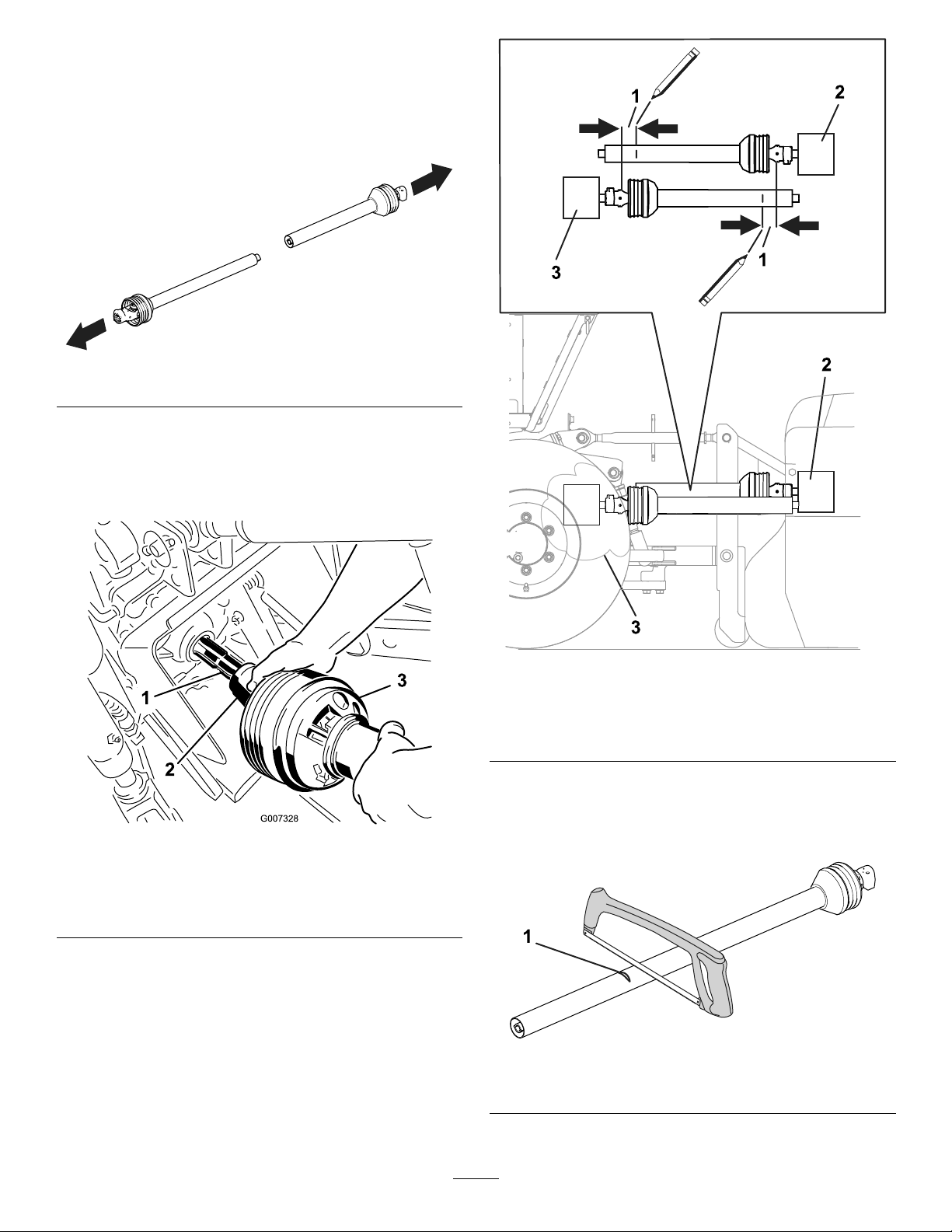
ConnectingthePTODriveshaft..........................9
ConnectingtheHydraulicHoses.......................13
AdjustingtheWorkingDepth.............................13
TransportingtheMachine.................................14
DuringOperation.................................................14
DuringOperationSafety...................................14
SlopeSafety.....................................................15
OperatingtheAttachment.................................15
OperatingTips.................................................18
AfterOperation....................................................18
AfterOperationSafety......................................18
RemovingtheAttachment................................18
Maintenance...........................................................20
RecommendedMaintenanceSchedule(s)...........20
MaintenanceSafety..........................................20
GreasingtheAttachment..................................21
CheckingtheGearboxLubrication....................21
ChangingtheGearboxLubrication...................22
InspectingtheBelts..........................................22
AdjustingtheV-BeltT ension.............................22
AdjustingtheConveyorBeltAlignment.............23
CleaningtheMachine.......................................24
InstallingtheCutterKnives...............................24
InstallingScarifyingKnives...............................25
Storage...................................................................29
StorageSafety..................................................29
PreparingtheMachineforStorage...................29
Troubleshooting......................................................30
Safety
GeneralSafety
Thisproductiscapableofcausingpersonalinjury.
Alwaysfollowallsafetyinstructionstoavoidserious
personalinjury.
•Readandunderstandthecontentsofboththis
Operator’sManualandtheoperator’smanualof
thetractionunitbeforeusingthismachine.Ensure
thateveryoneusingthisproductknowshowtouse
thismachineandthetractionunitandunderstands
thewarnings.
•Useyourfullattentionwhileoperatingthe
machine.Donotengageinanyactivitythat
causesdistractions;otherwise,injuryorproperty
damagemayoccur.
•Donotputyourhandsorfeetnearmoving
componentsofthemachine.
•Donotoperatethemachinewithoutallguards
andothersafetyprotectivedevicesinplaceand
workingonthemachine.
•Keepthemachineawayfrombystanderswhileit
ismoving.
•Keepchildrenoutoftheoperatingarea.Never
allowchildrentooperatethemachine.
•Stopthemachine,shutofftheengine,engage
theparkingbrakeofthetractionunit,removethe
key,andwaitforallmovingpartstostopbefore
servicing,fueling,oruncloggingthemachine.
Improperlyusingormaintainingthismachinecan
resultininjury.Toreducethepotentialforinjury,
complywiththesesafetyinstructionsandalways
payattentiontothesafety-alertsymbol,which
meansCaution,Warning,orDanger—personalsafety
instruction.Failuretocomplywiththeseinstructions
mayresultinpersonalinjuryordeath.
3

SafetyandInstructionalDecals
Safetydecalsandinstructionsareeasilyvisibletotheoperatorandarelocatednearanyarea
ofpotentialdanger.Replaceanydecalthatisdamagedormissing.
decal105-0698
105-0698
1.Warning—readtheOperator’sManual.
decal133-8061
133-8061
decal144-7905
144-7905
1.Thrownobject
hazard—keepbystanders
away.
2.Warning—removethekey,
securethemachinefrom
movement,andreadthe
Operator’sManualbefore
performingmaintenance.
decal144-7906
144-7906
1.Cutting/dismembermenthazardofthengers
decal144-7910
144-7910
1.Warning—entanglementhazard;keephandsawayfrom
movingparts.
decal144-7911
144-7911
1.Cuttinghazardofhand—closeandlockthecover.
decal144-8256
144-8256
1.PTO—350to540rpm
4

decal144-8338
144-8338
1.Entanglement
hazard—keepawayfrom
movingparts..
3.Warning—readthe
Operator’sManual.
2.Warning—removethe
keybeforeperforming
maintenance;readthe
Operator’sManual.
decal144-8339
144-8339
1.Entanglement
hazard—keepawayfrom
movingparts.
2.Warning—readthe
Operator’sManual.
5

Setup
InspectingtheMachine
CheckingtheGreaseandGearbox
Checkandensurethatthegearboxhasuid;referto
CheckingtheGearboxLubrication(page21).
Ensurethatthemachineisgreasedbeforeuse;refer
toGreasingtheAttachment(page21).
CheckingtheTractionUnit
Requirements
Usethefollowinglistandgureasareference:
•Refertothespecicationssectionfortheminimum
horsepower,maximumhorsepower,andthe
minimumliftingcapacity;Specications(page7).
•ThetractionunitmusthaveacategoryIorII
3-pointhitch.
•ThetractionunitmusthaveaPTOoutput-shaft
speedof540rpm.
•Adequatefront-endweight(ballast)tooffsetthe
weightofthemachine.
•Checkthetireairpressureofthetractionunit.
Adjustthetireairpressureasneeded.
Important:Donotexceedthemaximum
orminimumtireinationpressuresas
recommendedbytiremanufacturer.
g007332
Figure3
3-PointHitchandPTOComponents
1.Lowerlinkarm3.PTOdriveshaft
2.Upperlinkarm4.Swaylink
CheckingtheBallast
Requirements
WARNING
Mountingthemachinetotherearofthe
tractionunitdecreasestheweightonitsfront
axle.
Failuretoaddrequiredballastmayresultin
anaccidentandsevereinjuryordeath.
•Toensureadequatesteeringcontroland
stabilityyoumayneedtoaddballasttothe
frontofthetractionunit.
•Refertothetractionunitoperator'smanual
forballastrequirements.
6

ProductOverview
g346267
Figure4
1.Liftconveyor6.Frontroller
2.Adjustmentarm7.Rollerindicator
3.Hydraulichoses8.Beltcover
4.Frontlink9.Toolbox
5.3-pointhitchconnection
g346310
Figure5
1.Liftconveyor4.Cover
2.Debristransportbelt5.Latch
3.Rearlink
Specications
Note:Specicationsanddesignaresubjectto
changewithoutnotice.
TractionUnitRequirements
Tractorhorsepower30hpminimum
Minimumliftingcapacity(61
cm(24inches)fromlowerlink
pins)
775kg(1,709lb)
3-pointhitchCategory1orhigher
Hydraulicconnections1double-operatingvalve
AttachmentSpecications
Weight620kg(1,367lb)
Width185.4cm(73inches)
Length157.4cm(62inches)
Height221cm(87inches)
ConveyorheightUpto150cm(59-1/16inches)
Workingwidth120cm(47-1/4inches)
Workingdepth0to50mm(0to2inches)
Maximumworkingspeed3km/h(1.8mph)
PTOoutput-shaftspeed540rpm
Attachments/Accessories
AselectionofBullseyeapprovedattachmentsand
accessoriesmaybeavailableforusewiththemachine
toenhanceandexpanditscapabilities.Contactyour
AuthorizedServiceDealerorauthorizedBullseye
distributororgotowww.T oro.com/Bullseyeforalistof
allapprovedattachmentsandaccessories.
Toensureoptimumperformanceandcontinuedsafety
certicationofthemachine,useonlygenuineBullseye
replacementpartsandaccessories.Replacement
partsandaccessoriesmadebyothermanufacturers
couldbedangerous,andsuchusecouldvoidthe
productwarranty.
7

Operation
Note:Determinetheleftandrightsidesofthe
machinefromthenormaloperatingposition.
BeforeOperation
BeforeOperationSafety
•Neverallowchildrenoruntrainedpeopleto
operateorservicethemachine.Localregulations
mayrestricttheageoftheoperator.Theowner
isresponsiblefortrainingalloperatorsand
mechanics.
•Keepyourhandsclearofthejointpivotareas
whenhandlingthePTOdriveshaft.
•Donotstepon,over,orunderthePTOor
driveshafts.
•Becomefamiliarwiththesafeoperationofthe
equipment,operatorcontrols,andsafetysigns.
•Knowhowtostopthemachineandshutoffthe
engineofthetractionunitquickly.
•DonotusePTOsplineadaptersorextensions.
•Ensurethattheguardsandshieldsareproperly
installedandmaintained.Replacemissing,
damaged,orwornguardsandshieldsbeforeusing
themachine.
•EnsurethatthePTOdriveshaftdoesnotcontact
thedrawbar.
•Inspecttheareawhereyouwillusethemachine
andremoveallobjectsthatthemachinecould
strike.
•Ensurethatyourtractionunitissuitableforuse
withanimplementofthisweightbycheckingwith
yourtractionunitsupplierormanufacturer.
•Shutoffthemachine,shutofftheengineand
removethekeyofthetractionunit,andwait
forallmovingpartstostopbeforemakingany
adjustmentstothemachine.
UnderstandingtheTraction
UnitControls
Familiarizeyourselfwiththeoperationofthefollowing
tractionunitcontrolsbeforeoperatingthemachine:
•PTOengagement
•3pointhitch(raise/lower)
•Clutch
•Throttle
•Gearselection
•Parkingbrake
Important:Refertothetractionunitoperator's
manualforoperatinginstructions.
PracticingtheOperating
Procedures
Beforeusingthemachine,ndaclearareaand
practiceoperatingthetractionunitwiththemachine
installed.
Important:Iftherearesprinklerheads,electrical
orcommunicationlines,orotherobstructions
intheareabeingscariedorrenovated,mark
theselocationstoensurethattheseitemsarenot
damagedduringoperation.
•Operatethetractionunitusingtherecommended
gearsettingsandPTOdrivespeedsandbecome
thoroughlyfamiliarwiththetractionunithandling
withtheattachedmachine.
•Practicestoppingandstarting,raisingthe
machine,andloweringthemachine,disengaging
thePTOdrive,andaligningthemachinewith
previouspasses.
Practicesessionshelpsyougaincondenceinthe
performanceofthemachineandhelpsensurethat
youareusingitproperly.
WARNING
Adjustingormaintainingthemachinewhile
thetractionunitisrunningmayresultinan
accidentandsevereinjuryordeath.
•Lowerthemachineontothegroundor
jacksstandswhilerepairingthemachine.
•Beforeleavingtheoperator’sseat,
disengagethePTOdrive,engagethe
parkingbrake,shutofftheengine,remove
thekey,andwaitforallmovingpartsto
stop.
•Ensurethatallsafetydevicesaresecured
andinproperpositionbeforeresuming
operation.
Connectingtoa3-Point
Hitch
ConnectingtheLowerLinkArms
1.Ensurethattheattachmentispositionedona
levelsurface.
2.Removethehairpincottersfromthehitchpins
(Figure6).
8

g345540
Figure6
1.Hairpincotter(3)2.Hitchpin(3)
3.Backthetractionunitsquarelyuptothe
attachmentsothatyoucanattachthelower
connectingarmstotheframe.
4.Engagetheparkingbrake,shutofftheengine,
andremovethekeyfromtheignition.Waitfor
theengineandallmovingpartstostopbefore
leavingtheoperator'sseat.
Note:Formaximumgroundclearance,install
thehitchpinsinthelowermountingholesofthe
hitchplatefortheattachment.
5.Inserttherightandleftlowerlinkarmsontothe
hitchpins(Figure7).
g345538
Figure7
1.Lowerlinkarm(2)2.Hitchpinandhairpincotter
(2)
6.Securethelowerlinkarmstothehitchpins
usingthehairpincotters.
ConnectingtheUpperLinkArm
1.Connecttheupperlinkarmtothebracketand
secureitwiththelinkpinandthehairpincotter
(Figure8).
Note:Usetheslottedholeifyouwantthe
attachmenttofollowtheterrainduringoperation.
g345539
Figure8
1.Upperlinkarm4.Linkpin
2.Jamnut5.Slottedhole
3.Hairpincotter
2.Greasethethreadedsteelupperlinkarmtubes.
3.Rotatetheupperlinkarmtoshortenthelink.
Adjustituntiltheattachmentisatonthe
ground.
4.Tightenthejamnuttosecuretheupperlinkarm
intoposition.
5.Startthetractionunitandlifttheattachmentoff
theground.
ConnectingthePTO
Driveshaft
AdjustingthePTODriveshaft
Length
AdjustthelengthofthePTOdriveshaftwheneveryou
installtheattachmenttoadifferenttractionunit.
Important:IfthelengthofPTOisnotadjusted
properly,usingtheattachmentcandamagethe
tractionunitortheattachment.Theoverlapping
lengthofthecylindersmustbeatleast150mm
(6inches).Thelengthchangeswhenyouliftor
installtheattachmentonadifferenttractionunit.
9

1.Parkthemachineonalevelsurface,engage
theparkingbrake,andlowertheattachmentto
theground.
2.Shutofftheengineandremovethekey.
3.PullthePTOdriveshaftsectionsapart(Figure9).
g347461
Figure9
4.AssembletheouterPTOdriveshaftsectionto
thetraction-unitPTOoutputshaft(Figure10).
Note:Pullonthedriveshafttoensurethatthe
lockingpinengagesthePTOoutputshaft.
g007328
Figure10
1.PTOoutputshaft(traction
unit)
3.PTOdriveshaft
2.PTOshaftcoupler
5.Holdthedriveshaftsectionsparalleltoeach
othertodetermineiftheyaretoolong(Figure
11).
Note:Eachdriveshaftsectionmustbe76mm
(3inches)fromtheU-joint(Figure11).
6.Ifthedriveshaftsectionsaretoolong,mark76
mm(3inches)backfromU-jointoneachsection
(Figure11).
g347524
Figure11
1.76mm(3inches)3.Traction-unitPTOoutput
shaft
2.Attachmentgearbox
7.Removeandcuteachsectionatthemark
(Figure12).
Note:Ensurethesameamountisremoved
fromeachsection.
g347473
Figure12
1.Cutthedriveshaftsection.
8.Deburrtheendsofthesections(Figure13).
10

g347459
Figure13
9.AssembletheouterPTOdriveshaftsectionto
thePTOshaftofthetractionunit(Figure10).
10.Raisetheattachmenttothepositionwherethe
traction-unitPTOoutputshaftandgearboxinput
shaftarefurthestapart(Figure14).
11.Holdthedriveshaftsectionsparalleltoeach
otherandchecktoensurethattheyoverlap150
mm(6inches)ormore(Figure14).
Note:Ifthesectionsdonotoverlap150mm(6
inches),contactyourauthorizeddistributor.
g347621
Figure14
1.Attachmentgearbox3.Shaftsfurthestapart
2.Traction-unitPTOoutput
shaft
12.Greaseandassemblethesections.
Important:Donotusetheattachmentif
thePTOdriveshaftisdamaged;replacethe
damageddriveshaftbeforeoperation.
11

InstallingthePTODriveshaft
Important:RefertothePTOdriveshaftowner’s
manualforadditionaloperatingandsafety
information.
CAUTION
OperatingthemachinewithoutthePTO
guardsandshieldsmaycauseinjuryordeath.
KeepallPTOguardsandshieldsinplace.
Important:WhenconnectingthePTO,ensure
thattheattachmentisnotliftedhigherthan
necessary.Liftingtheattachmenttoohighcauses
thePTOdriveshaftknucklestobreak(Figure15).
ThePTOcanoperateuptoanangleof25°,
butoperatingitbeyond30°anglemayseverely
damagetheshaft.
Note:Ensurethecrossbearingsarealignedas
showninFigure15.
g345626
Figure15
1.Breakageoccurshere.
1.AssemblethePTOdriveshafttothegearbox
inputshaftoftheattachment.
g345541
Figure16
1.Gearboxinputshaft4.Bolt
2.Nut5.PTOdriveshaft
3.PTOshaftcoupler
2.AssemblethePTOdriveshafttothePTOoutput
shaftofthetractionunit.
g007328
Figure17
1.PTOoutputshaft(traction
unit)
3.PTOdriveshaft
2.PTOshaftcoupler
3.SlidethePTOdriveshaftforwardasfarasthe
PTOoutputshaftallows.
4.PullbackonthelockingcollarofthePTOshaft
couplertosecurethePTOdriveshaft.Slidethe
PTOdriveshaftbackandforthtoensurethatit
islockedsecurely.
12

5.Verifythatthetelescopingtubehasaminimum
of150mm(6inches)overlapwhenthe
attachmentisraisedtothemaximumheight.
g345507
Figure18
ConnectingtheHydraulic
Hoses
1.Connectthehydraulichosesfromtheattachment
tothetractionunit.Ensurethehydraulichoses
areengagedintheports.
2.Conrmthatthetractionunitleversoperatethe
attachmenthydraulics.
AdjustingtheWorking
Depth
Theworkingdepthissetbyadjustingthefrontroller.
Ensuretherearrollerissettothelongslotforcutting
andscarifying(Figure19).
Important:Adjusttheworkingdepthonlywhen
thetractionunitisparked,theparkingbrakeis
engaged,thePTOisdisengaged,andtheengine
isshutoff.
1.Loosenthejamnutonthetopofeachrearlink.
2.Adjusttherearlinksuntiltheyalignwiththelong
slotinthegauge(Figure19).
3.Tightenthejamnutonthetopofeachrearlink
(Figure19).
g346323
Figure19
1.Rearlink4.Rearlink
2.Jamnut5.Longslotingauge
3.Gauge
4.Loosenthejamnutoneachfrontlink.
5.Adjustthefrontlinkstoyourdesireddepthby
usingtheindicatorsonthesides.
6.Tightenthejamnutoneachfrontlink.
7.Checktheworkingdepthbyrunningthemachine
afewmeters(yards).RefertoOperatingthe
Attachment(page15).
8.Ifneeded,adjustthefrontlinksuntilyoureach
yourdesireddepth.
Note:Whentheliftconveyorisfoldedout,the
machineweightshiftstothisside.Duetothe
extraweight,youcanremovemorematerialon
thisside.Tocompensateforthisextraweight,
adjustthefrontandbacklinksontherightside
(liftconveyorside).
13

g346328
Figure20
1.Frontlink3.Adjustmentpositions
2.Jamnut4.Frontindicator
TransportingtheMachine
Topreventlosingcontrolofthemachine,moveslowly
acrosssteepinclinesandapproachrough,undulating
areasslowlyandcarefully.
Important:Donotexceed12km/h(7.5mph)
whiletransportingtheattachment.
1.Parkthetractionunitandmachineonalevel
surface,disengagethePTO,engagetheparking
brake,shutofftheengine,removethekey,and
waitforallmovingpartstostopbeforeleaving
theoperator'sseat.
2.Movetheliftconveyortothetransportposition.
3.Raisetheattachmentanddrivethetractionunit,
notexceeding12km/h(7.5mph).
DuringOperation
DuringOperationSafety
•Theowner/operatorcanpreventandisresponsible
foraccidentsthatmaycausepersonalinjuryor
propertydamage.
•Wearappropriateclothing,includingeye
protection;longpants;substantial,slip-resistant
footwear;andhearingprotection.Tiebacklong
hairanddonotwearlooseclothingorloose
jewelry.
•Useyourfullattentionwhileoperatingthe
machine.Donotengageinanyactivitythat
causesdistractions;otherwise,injuryorproperty
damagemayoccur.
•Donotoperatethemachinewhentired,ill,or
undertheinuenceofalcoholordrugs.
•Nevercarrypassengersonthemachineandkeep
bystandersandpetsawayfromthemachine
duringoperation.
•Operatethemachineonlyingoodvisibilitytoavoid
holesorhiddenhazards.
•Beforeyoustarttheengine,ensurethatalldrives
areinneutral,thePTOisdisengaged,theparking
brakeisengaged,andyouareintheoperating
position.
•Keepyourhandsandfeetawayfrommovingparts.
•Lookbehindanddownbeforebackinguptobe
sureofaclearpath.
•Usecarewhenapproachingblindcorners,shrubs,
trees,orotherobjectsthatmayobscureyour
vision.
•DonotrunthePTOwiththeattachmentraised.
•Stoptheattachmentwheneveryouarenotusingit.
•Stopthemachine,shutofftheengine,removethe
key,waitforallmovingpartstostop,andinspect
themachineafterstrikinganobjectorifthereis
anabnormalvibrationinthemachine.Makeall
necessaryrepairsbeforeresumingoperation.
•Slowdownandusecautionwhenmakingturns
andcrossingroadsandsidewalkswiththe
machine.Alwaysyieldtheright-of-way.
•Reducespeedonroughroadsandsurfaces.
•Whenattachedtoatractionunit,andintheraised
position,theweightoftheattachmentaffects
stability,brakingandsteering.Exercisecaution
whentransportingbetweenworkingareas.
•Neverleavearunningmachineunattended.
•Beforeleavingtheoperatingposition,dothe
following:
–EnsurethatthePTOisdisengaged.
–Parkthemachineonalevelsurface.
14

–Engagetheparkingbrake.
–Lowertheattachment.
–Shutofftheengineandremovethekey.
–Waitforallmovingpartstostopbeforeleaving
themachine.
•Donotoperatethemachinewhenthereistherisk
oflightning.
•UseBullseyeaccessories,attachments,and
replacementpartsonly.
•FordisassemblyorrepairofallsteelPTO
driveshaftparts(tubes,bearings,joints,etc.),
contactyourauthorizeddistributor.Removing
componentsforrepairsandassemblymay
damagesomepartsifnotperformedwithspecial
toolsbytrainedtechnicians.
•DonotoperatetheattachmentifthePTOor
driveshaftguardsaremissing.
•Becarefulwhenturningthemachinesothat
thetractionunittiresdonotcontactthePTO
driveshaft.
•Securehydraulichoses,electricalwiring,ropes,
andotheritemstokeepthemfromcontactingthe
PTOdriveshaftguard.
SlopeSafety
•Reviewthetractionunitspecicationstoensure
thatyoudonotexceeditsslopecapabilities.
•Slopesareamajorfactorrelatedtolossofcontrol
androlloveraccidents,whichcanresultinsevere
injuryordeath.Youareresponsibleforsafeslope
operation.Operatingthemachineonanyslope
requiresextracaution.
•Reviewandunderstandtheslopeinstructionsin
themanualandonthetractionunit.
•Evaluatethesiteconditionstodetermineifthe
slopeissafeformachineoperation,including
surveyingthesite.Alwaysusecommonsense
andgoodjudgmentwhenperformingthissurvey.
•Reviewtheslopeinstructionslistedbelowfor
operatingthemachineonslopesandtodetermine
whetheryoucanoperatethemachineinthe
conditionsonthatdayandatthatsite.Changes
intheterraincanresultinachangeinslope
operationforthemachine.
•Avoidstarting,stopping,orturningthemachineon
slopes.Avoidmakingsuddenchangesinspeedor
direction.Maketurnsslowlyandgradually.
•Donotoperateamachineunderanyconditions
wheretraction,steering,orstabilityareinquestion.
•Removeormarkobstructionssuchasditches,
holes,ruts,bumps,rocks,orotherhiddenhazards.
Tallgrasscanhideobstructions.Uneventerrain
couldoverturnthemachine.
•Beawarethatoperatingthemachineonwet
grass,acrossslopes,ordownhillmaycausethe
machinetolosetraction.Lossoftractiontothe
drivewheelsmayresultinslidingandalossof
brakingandsteering.
•Useextremecautionwhenoperatingthemachine
neardrop-offs,ditches,embankments,water
hazards,orotherhazards.Themachinecould
suddenlyrolloverifawheelgoesovertheedge
ortheedgecavesin.Establishasafetyarea
betweenthemachineandanyhazard.
•Identifyhazardsatthebaseoftheslope.If
therearehazards,mowtheslopewithapower
walk-behindmower.
•Ifpossible,keeptheattachmentloweredtothe
groundwhileoperatingonslopes.Raisingthe
attachmentwhileoperatingonslopescancause
themachinetobecomeunstable.
•Useextremecautionwithotherattachments.
Thesecanchangethestabilityofthemachineand
causealossofcontrol.Alwayskeepthemachine
ingearwhengoingdownslopes.Donotcoast
downhill(applicableonlytogear-driveunits).
OperatingtheAttachment
UsingthePTO
BeforeengagingthePTO,verifythefollowing:
•Theangleofthepivotpinsare25°orlessand
neverexceeding30°.
•Thepivotpinsarealigned.
•TheoverlapofthePTOcylindersisatleast150
mm(6inches).
•ThePTOprotectionguardisnotdamaged.
StartingtheAttachment
WARNING
Liftingtheattachmenttoohighcausesthe
PTOdriveshaftknucklestobreak.
Ensurethattheattachmentisnotliftedhigher
thanisnecessary.
Important:
ThePTOcanoperateuptoanangleof25°,
butoperatingitbeyond30°anglemayseverely
damagetheshaft(Figure21).
15

g345626
Figure21
1.Breakageoccurshere.
1.Drivetothelocationwhereyouwillusethe
attachment
2.Inspecttheareawhereyouwillusethemachine
andremoveallobjectsthatthemachinecould
strike.
3.Locateandmarkallelectricalorcommunication
lines,irrigationcomponents,andother
obstructionsinthearea.
4.Parkthemachineonalevelsurfaceandlower
theattachment.
5.Engagetheparkingbrake,shutofftheengine,
andremovethekeyfromthetractionunit.
6.Adjusttheliftconveyorandsecurethearmin
thedesiredposition(Figure22).
Note:Ensurethereisenoughclearancearound
themachinewhereyouunfoldtheconveyor.
g346288
Figure22
1.Conveyorarm3.Middleposition
2.Extendedposition4.Transportposition
7.Adjusttheworkingdepthoftheattachment;refer
toAdjustingtheWorkingDepth(page13).
8.Mounttheupperlinkarmintheslottedholeso
thattheattachmentfollowstheterrain;referto
ConnectingtheUpperLinkArm(page9).
9.Startthetractionunitandraisetheattachment
sothattheknivesdonottouchtheground.
WARNING
Theconveyorbeltsarerotatingwhen
removingdebrisandcouldcauseserious
injury.
•Keepawayfrommovingparts.
•Keepclearofthedischargeopening.
•Ensurethereisclearanceforthe
secondmachinecollectingthedebris.
10.Allowasecondmachineforcollectingthedebris
todriveundertheconveyor.
11.Engagethetractionunitintothepropergear.
12.Activatethehydraulicvalveonthetractionunit
toengagethehorizontalbeltandthetransport
belt.
13.Lowertheattachmentuntilitisapproximately50
mm(2inches)abovetheground.
16

14.EngagethetractionunitPTOatalowengine
speed.
15.IncreasethetractionunitPTOspeedto
approximately300rpm.
16.Drivethetractionunitforwardslowlyandallow
theattachmenttosmoothlylowerontothe
rollers.
Note:Ensurethesecondmachineisfollowing
tocollectthedebris.
17.Slowlylowertheattachmentuntilitreachesthe
workingdepth.
18.Driveforwardandincreasetherotationalspeed
untilthePTOdriveshaftspeedreaches540rpm.
19.Increasethetractionunitspeedtoamaximum
of3km/h(1.8mph).
Important:Ensurethespeedofthetraction
unitdoesnotexceed3km/h(1.8mph).
20.Drivethetractionunitandattachmentafew
meters(yards)andchecktheworkingdepth.
Ifnecessary,adjusttheworkingdepthas
describedinAdjustingtheWorkingDepth(page
13).
21.Afteroperatingtheattachment,closethe
hydraulicvalveonthetractionunittostop
thebeltsandturnaroundbyraisingitto
approximately50mm(2inches)abovethe
ground.
Note:Ensurethereisenoughclearancearound
themachinewhereyouturnaround.
22.Afterturningaround,allowthesecondmachine
todriveundertheconveyor,openthehydraulic
valveonthetractionunittostartthebelts,lower
theattachment,andcontinueoperation.
StoppingtheAttachment
1.DecreasethePTOdriveshaftspeedto
approximately300rpmbydecreasingthe
enginespeed.
2.Liftthemachineslightlyofftheground.
3.SwitchthePTOoffassoonastheknivesno
longertouchthesoil.
4.Closethehydraulicvalveonthetractionunitto
stopthebelts.
5.Lifttheattachment.
6.Allowthesecondmachinetomoveawayfrom
theconveyor.
7.Gotothenextworkarea.
17

OperatingTips
•EngagethePTOatlowenginespeed.Lowerthe
machineandincreaseenginespeedtoachieve
aPTOspeedof540rpm(maximum).Operate
theengineataspeedthatthemachinerunsmost
smoothly.
•Makeverygradualturns.Nevermakesharpturns
withthemachinelowered.Planyourpathbefore
loweringthemachine.
•Donotusetheattachmentifthegroundistoowet.
•Raisetheworkingdepthifthegroundishard
packed.
•Alwayscheck/adjustthetoplinkwheneveryou
changethedepth.Thefrontoftheattachment
shouldbevertical.
•Lookbackwardfrequentlytoensurethatthe
machineisoperatingproperly,thesecondmachine
forcollectingthedebrisisfollowing,andthe
alignmentismaintainedwithpreviouspasses.
•Replacebrokenknives,andinspectandcorrect
damagetothosestillusable.Repairanyother
machinedamagebeforeresumingoperation.
AfterOperation
AfterOperationSafety
•Parkthemachineonalevelsurface;engagethe
parkingbrake;shutofftheengine;removethekey;
andwaitforallmovementtostopbeforeleaving
themachine.
•Donotstepon,over,orunderthedriveshaft.
•DonotusetherestrainchainofthePTO-shaft
guardtosupporttheshaftwhentransportingor
storingthemower.
•DonotrestthePTOshaftontheground.
•DonotallowthePTO-shaftguardstopullapart.
•Keepallpartsofthemachineingoodworking
conditionandallhardwaretightened.
•Replaceallworn,damaged,ormissingdecals.
RemovingtheAttachment
1.Parkthemachineonalevelsurfaceandengage
theparkingbrake.
2.Lowerthefrontandrearrollersenoughtoallow
theattachmenttorestontherollerswithoutthe
knivestouchingtheground.RefertoAdjusting
theWorkingDepth(page13).
3.Lowertheattachmentontotherollers.
4.Shutofftheengineandremovethekeyfrom
thetractionunit.
5.Removethehydraulichosesfromthetraction
unit.
6.Removethetoplinkfromtheattachment.
g345539
Figure23
1.Upperlinkarm4.Linkpin
2.Jamnut5.Slottedhole
3.Hairpincotter
7.RemovethePTOshaftfromthetractionunit.
g007328
Figure24
1.PTOoutputshaft(traction
unit)
3.PTOdriveshaft
2.PTOshaftcoupler
8.Removethelowerlinksfromtheattachment.
Important:Ensurethattheattachmentdoes
notrollwhenoffthetractionunit.
18

g345538
Figure25
1.Lowerlinkarm(2)2.Hitchpinandhairpincotter
(2)
9.Startthetractionunitanddriveitawayfromthe
attachment.
10.Installthehairpincottersintothehitchpins.
g345540
Figure26
1.Hairpincotter(3)2.Hitchpin(3)
19

Maintenance
RecommendedMaintenanceSchedule(s)
MaintenanceService
IntervalMaintenanceProcedure
Aftertherst20hours
•GreasethePTOshaftandrollerbearings.
•Checkthegearboxoillevel.
•Checkthegearboxforleaks.
•ChecktheV-belttension.
•Checkforloosenutsandbolts.
Beforeeachuseordaily
•Checkthegearboxoillevel.
•Checkforloosenutsandbolts.
•CheckthePTOshaft.
•Checkthehydraulics.
•Checktheconveyorbelts.
Aftereachuse•Greasethebearingswith1shot.
•Cleanthemachine.
Every50hours
•Greasethebearingsandbushings.
•Checkthegearboxoillevel.
•Checkthegearboxforleaks.
•ChecktheV-belttension.
•Checkforloosenutsandbolts.
Every500hours•Changethegearboxoil.
Beforestorage
•Performall50-hourmaintenanceprocedures.
•Paintareasthatarescratched,chipped,orrusted.
•Removealldebris.
CAUTION
Ifyouleavethekeyintheswitch,someonecouldaccidentlystarttheengineandseriously
injureyouorotherbystanders.
Removethekeyfromtheswitchbeforeyouperformanymaintenance.
MaintenanceSafety
•Beforeadjusting,cleaning,servicing,orleaving
themachine,dothefollowing:
–Positionthemachineonalevelsurface.
–Movethethrottleswitchtothelow-idleposition.
–DisengagethePTO(ifapplicable).
–Ensurethatthetractionisinneutral.
–Engagetheparkingbrake.
–Shutofftheengineofthetractionunitand
removethekey.
–Waitforallmovingpartstostop.
–Allowmachinecomponentstocoolbefore
performingmaintenance.
•Performonlythosemaintenanceinstructions
describedinthismanual.Ifmajorrepairsare
everneededorassistanceisdesired,contactan
authorizedBullseyedistributor.
•Ensurethatthemachineisinsafeoperating
conditionbykeepingnuts,bolts,andscrewstight.
•Ifpossible,donotperformmaintenancewhilethe
engineisrunning.Keepawayfrommovingparts.
•Carefullyreleasepressurefromcomponentswith
storedenergy.
•Supportthemachinewithblocksorstoragestands
whenworkingbeneathit.Neverrelyonthe
hydraulicsystemtosupportthemachine.
•Nevercrawlundertheattachment.Ifnecessary,
tilttheattachment.
•Ensurethatallguardsareinstalledandsecured
aftermaintainingoradjustingthemachine.
•Toensuresafe,optimalperformanceofthe
machine,useonlygenuineBullseyereplacement
parts.Replacementpartsmadebyother
manufacturerscouldbedangerous,andsuchuse
couldvoidtheproductwarranty.
20
This manual suits for next models
1
Table of contents
Other Toro Lawn And Garden Equipment manuals

Toro
Toro 04475 User manual

Toro
Toro Greensmaster TriFlex 3300 Series User manual

Toro
Toro AERATOR HC 4000 User manual

Toro
Toro 02980 User manual

Toro
Toro Bullseye QuickGroom 550 User manual

Toro
Toro T7 Series User manual

Toro
Toro MULTI PRO 5600 User manual

Toro
Toro 686 User manual

Toro
Toro Sand Pro 3040 User manual

Toro
Toro Wheel Horse 79375 User manual

Toro
Toro 22615 User manual

Toro
Toro ProCore 864 User manual

Toro
Toro Groundsmaster 120 User manual

Toro
Toro ECx User manual

Toro
Toro POWER MAX HD User manual

Toro
Toro 136-2881 User manual

Toro
Toro Groundsmaster 3320 Series User manual

Toro
Toro 09501 User manual

Toro
Toro 41339 User manual

Toro
Toro 44922 User manual