ProcedureDescriptionQty.Use
Delaytimer1
Locknut(#10–24)2
Fuse(40A)1
Relay1
Powerrelay1
Flange-headbolt(#10-24x1/2inch)2
3-positionswitch(withindicator
light—2015andbeforeturfsprayers)1
7
3-positionswitch(withoutindicator
light—2016andafterturfsprayers)1
Installthedelaytimeranddashswitch.
8Nopartsrequired–Finishtherinsetankkitinstallation.
1
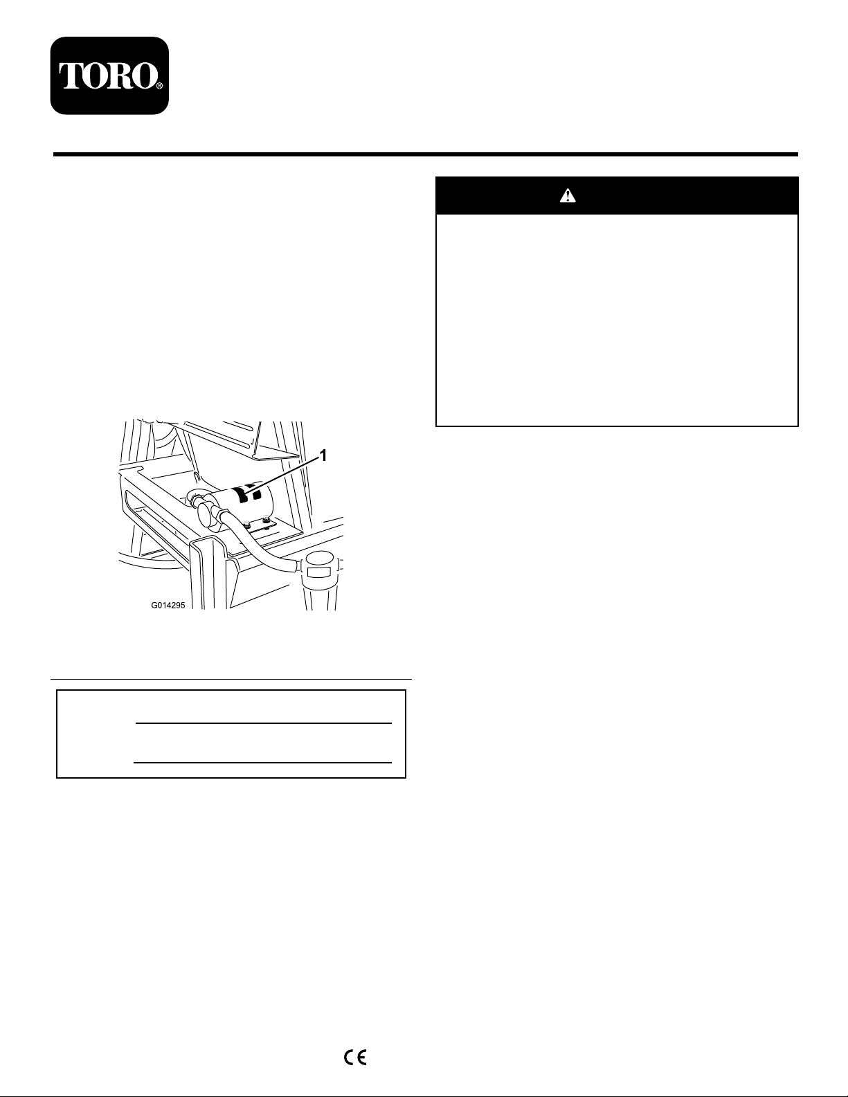
PreparingtheMachine
NoPartsRequired
PreparingtheSprayerSystem
CAUTION
Chemicalsarehazardousandcancause
personalinjury.
•Readthedirectionsonthechemicallabels
beforehandlingthechemicalsandfollow
allmanufacturerrecommendationsand
precautions.
•Keepchemicalsawayfromyourskin.
Shouldcontactoccur,washtheaffected
areathoroughlywithsoapandcleanwater.
•Weargogglesandanyotherprotective
equipmentrecommendedbythechemical
manufacturer.
1.Movethemachinetoalevelsurface,fullypress
inthebrakepedal,settheparkingbrake,turnoff
theengine,andremovethekey.
2.Cleanthesprayer;refertoCleaningtheSprayer
intheOperator’sManualforthemachine.
Note:Takecautionwhiledisconnectingany
hosesduringtheinstallationofthiskitandhave
acatchbucketreadyforanysolutionsremaining
inthehose.
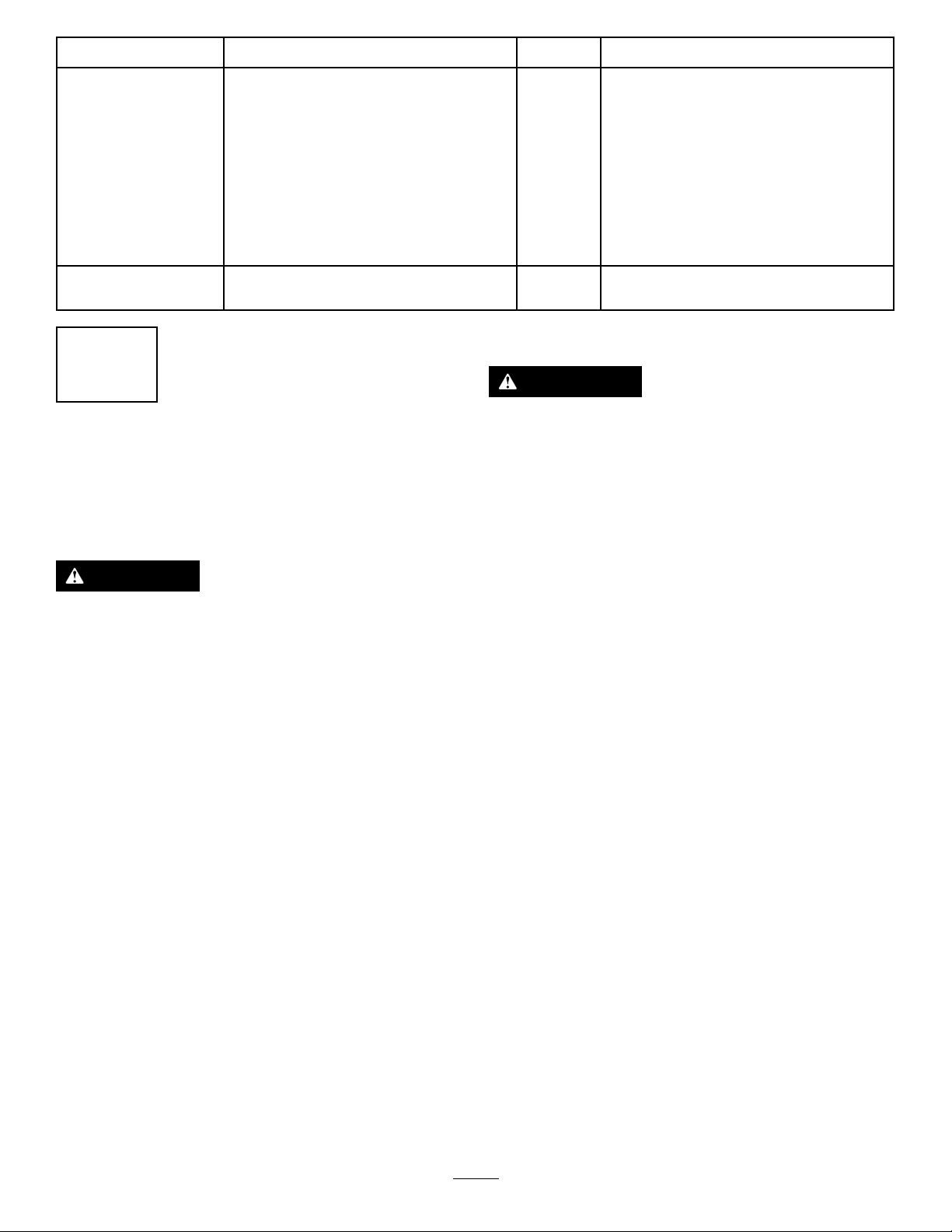
DisconnectingtheBattery
WARNING
Electricalsparkscancausethebatterygasses
toexplode,resultinginpersonalinjury.
Incorrectbatterycableroutingcoulddamage
thesprayerandcables,causingsparks.
•Alwaysdisconnectthenegative(black)
batterycablebeforedisconnectingthe
positive(red)cable.
•Alwaysconnectthepositive(red)battery
cablebeforeconnectingthenegative
(black)cable.
Batteryterminalsormetaltoolscouldshort
againstmetalsprayercomponents,causing
sparks.
•Whenremovingorinstallingthebattery,
donotallowthebatteryterminalstotouch
anymetalpartsofthesprayer.
•Donotallowmetaltoolstoshortbetween
thebatteryterminalsandmetalpartsof
thesprayer.
•Alwayskeepthebatterystrapinplaceto
protectandsecurethebattery.
1.Removethebatterycoveranddisconnectthe
negative(black—ground)cablefromthebattery
post(Figure2andFigure3).
4