Toro Pro Sneak 360 User manual
Other Toro Lawn Mower Accessories manuals
Toro
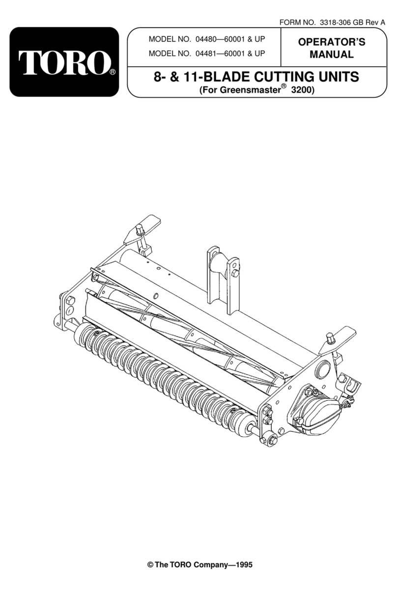
Toro 04480 User manual

Toro
Toro Groundsmaster 4500-D User manual
Toro
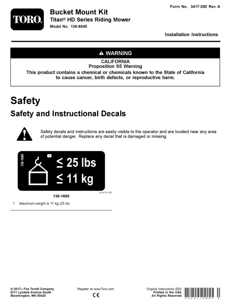
Toro 136-9045 User manual
Toro
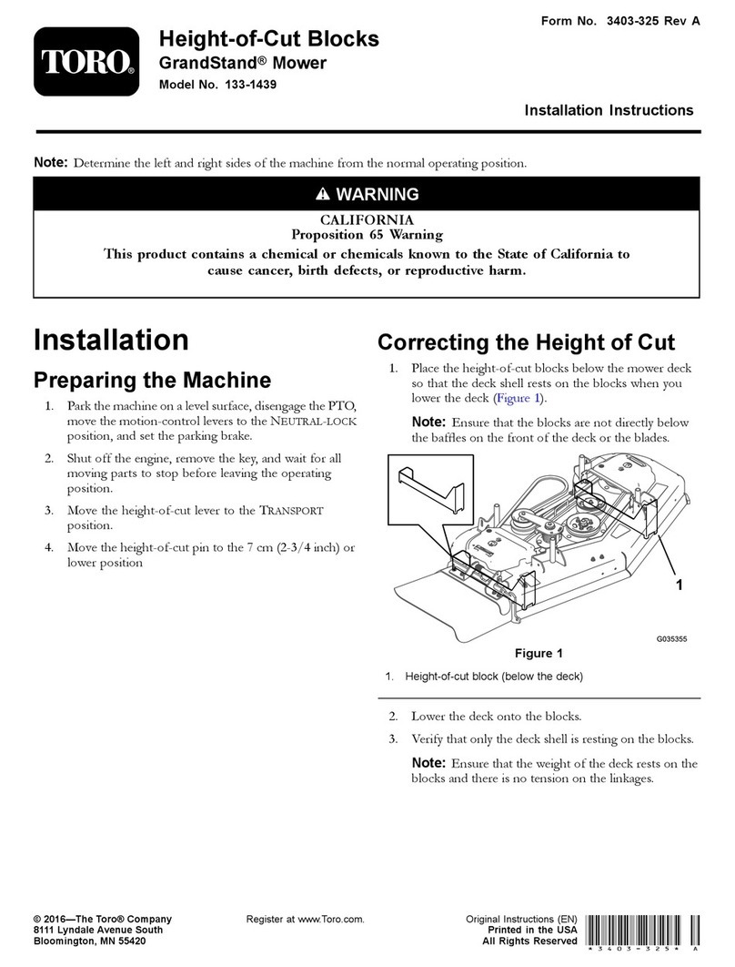
Toro GrandStand 133-1439 User manual
Toro
Toro 30104 User manual
Toro
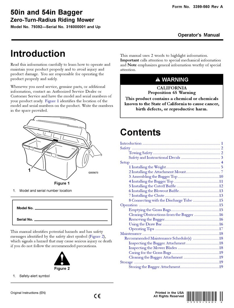
Toro 79392 User manual
Toro
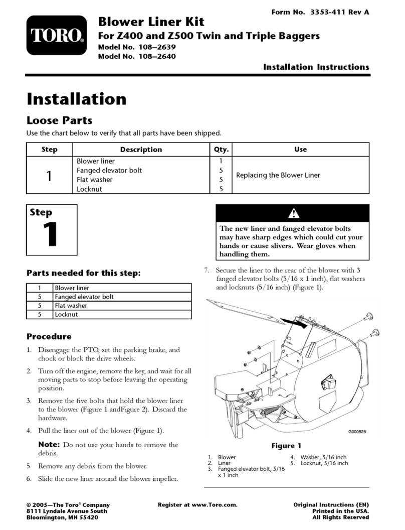
Toro 108-2639 User manual
Toro
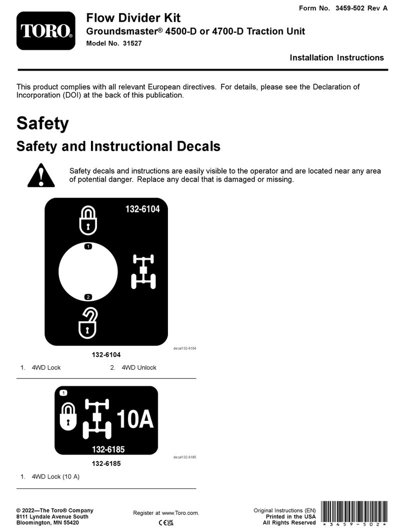
Toro 31527 User manual

Toro
Toro Groundsmaster 360 Series User manual
Toro
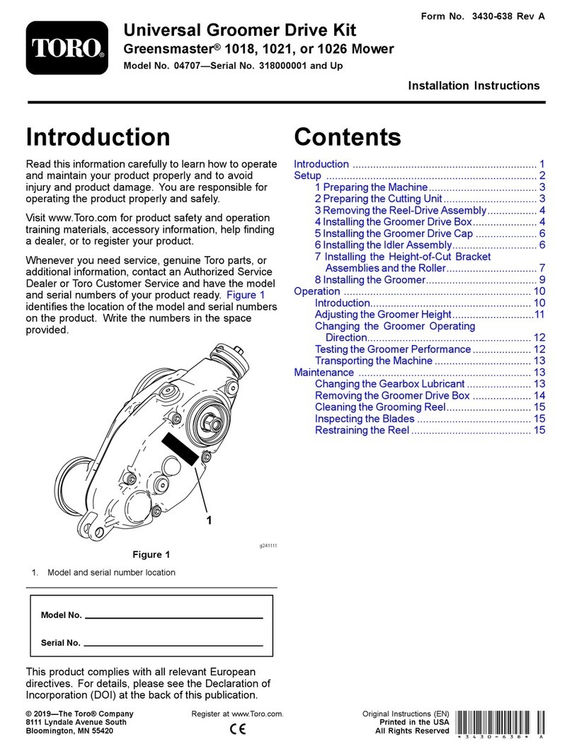
Toro 04707 User manual

Toro
Toro Wheel Horse 78361 User manual

Toro
Toro CT Series User manual

Toro
Toro Groundsmaster 31511 User manual
Toro
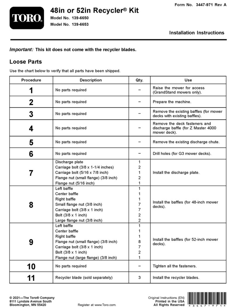
Toro 139-6650 User manual
Toro
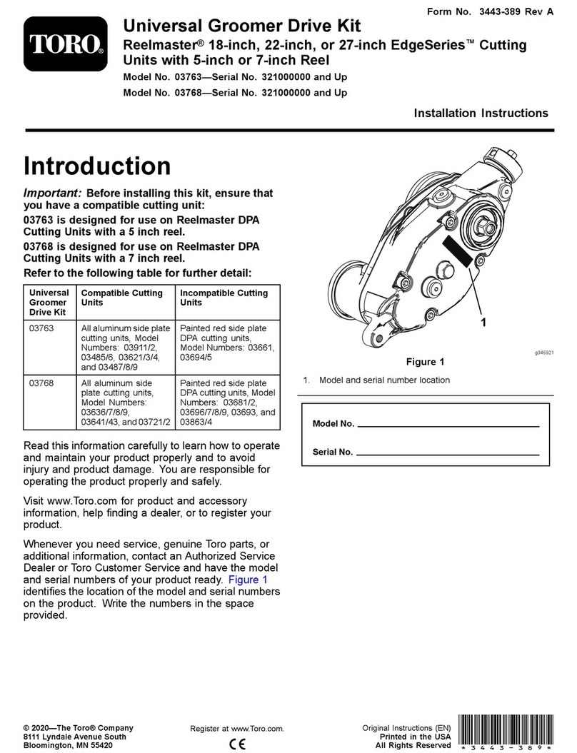
Toro Universal Groomer Drive Kit User manual
Toro
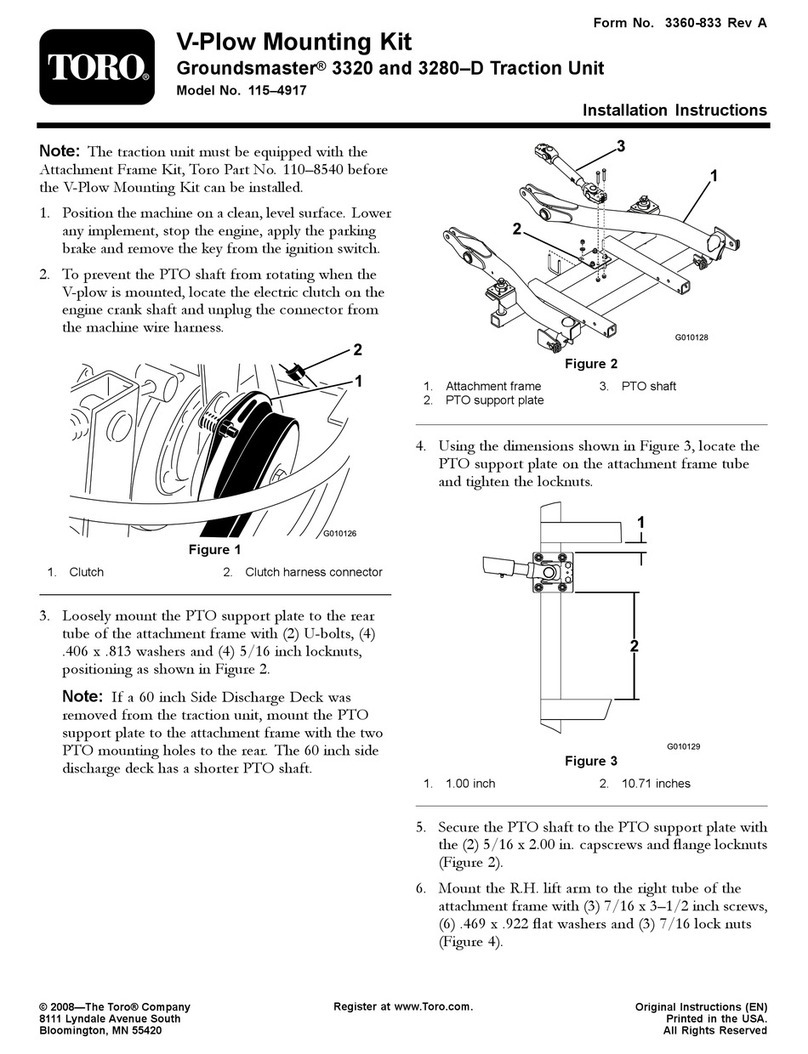
Toro 115-4917 User manual

Toro
Toro 3200 User manual
Toro
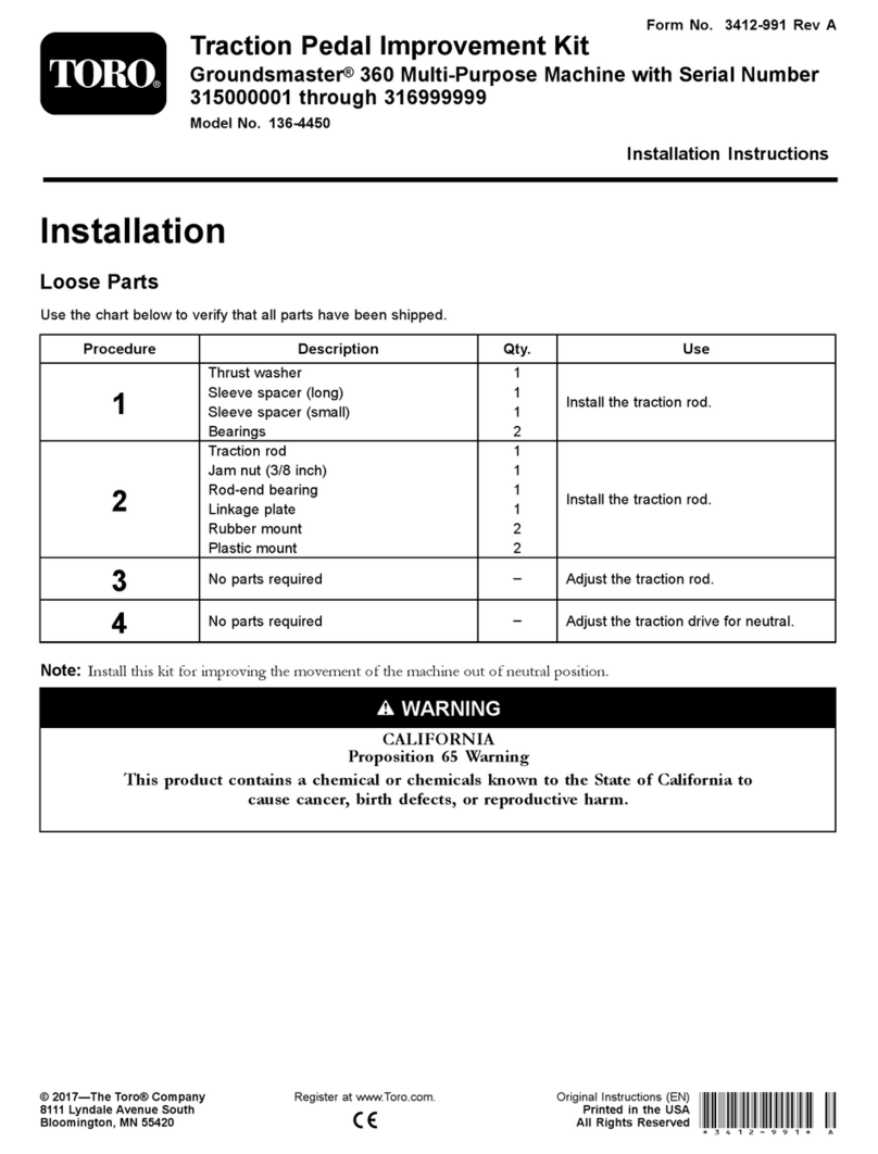
Toro Groundsmaster 136-4450 User manual
Toro
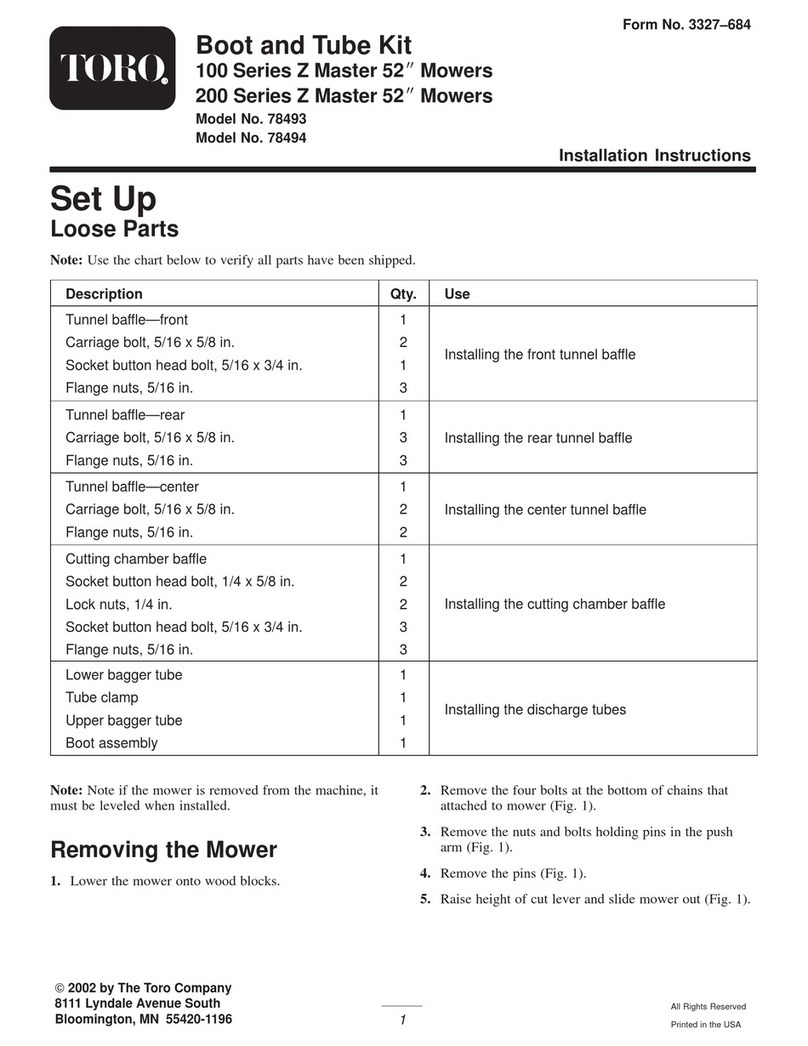
Toro 78493 User manual
Toro
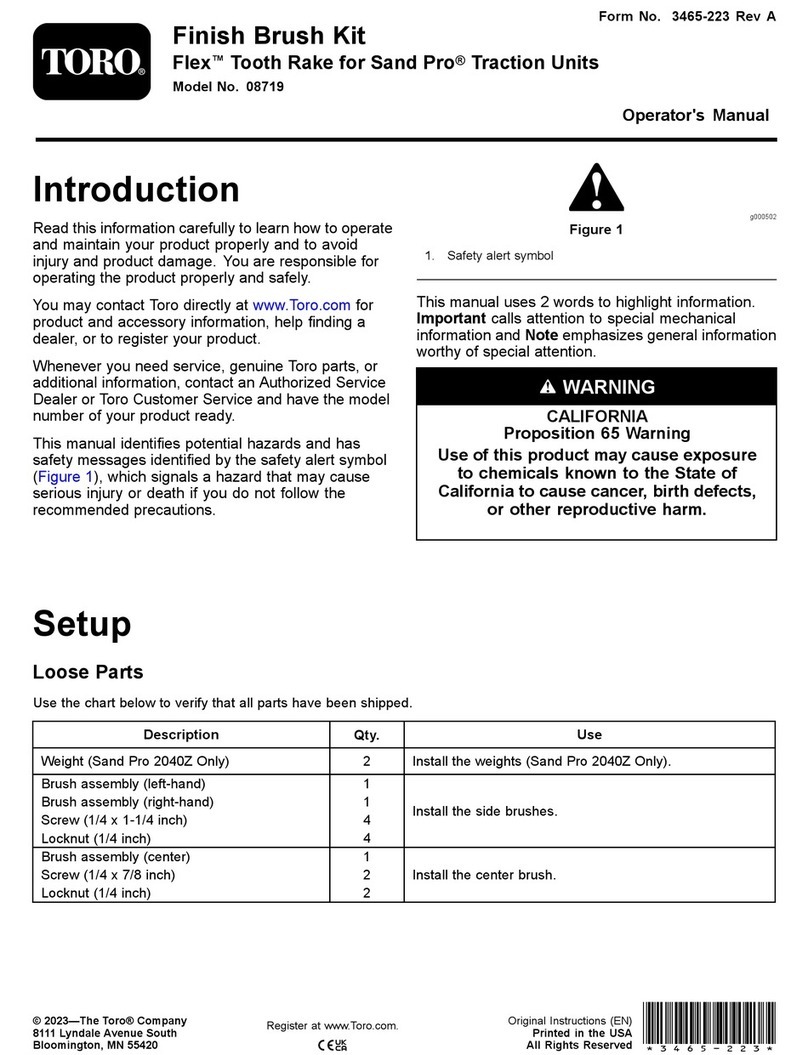
Toro 08719 User manual
