Toro 78555 User manual

FormNo.3438-488RevA
48inand52inE-ZVac™Twin
BaggingSystemor60inand72in
E-ZVac™TripleBaggingSystem
ZMaster®G3Mower
ModelNo.78555—SerialNo.400000000andUp
ModelNo.78562—SerialNo.405700000andUp
ModelNo.78563—SerialNo.405700000andUp
Registeratwww.Toro.com.
OriginalInstructions(EN)*3438-488*A

ThisproductcomplieswithallrelevantEuropean
directives.Fordetails,pleaseseetheDeclarationof
Incorporation(DOI)atthebackofthispublication.
WARNING
CALIFORNIA
Proposition65Warning
Useofthisproductmaycauseexposure
tochemicalsknowntotheStateof
Californiatocausecancer,birthdefects,
orotherreproductiveharm.
Introduction
Readthisinformationcarefullytolearnhowtooperate
andmaintainyourproductproperlyandtoavoid
injuryandproductdamage.Youareresponsiblefor
operatingtheproductproperlyandsafely.
Visitwww.Toro.comforproductsafetyandoperation
trainingmaterials,accessoryinformation,helpnding
adealer,ortoregisteryourproduct.
Wheneveryouneedservice,genuineT oroparts,or
additionalinformation,contactanAuthorizedService
DealerorT oroCustomerServiceandhavethemodel
andserialnumbersofyourproductready.Figure1,
Figure2andFigure3identiesthelocationofthe
modelandserialnumbersontheproduct.Writethe
numbersinthespaceprovided.
g003368
Figure1
1.Blowermodelandserialnumberlocation
ModelNo.
SerialNo.
g009306
Figure2
48-and52-inchbaggerserialnumber
1.Baggermodelandserialnumberlocation
g009416
Figure3
60-and72-inchbaggerserialnumber
1.Baggermodelandserialnumberlocation
ModelNo.
SerialNo.
Thismanualidentiespotentialhazardsandhas
safetymessagesidentiedbythesafetyalertsymbol
(Figure4),whichsignalsahazardthatmaycause
seriousinjuryordeathifyoudonotfollowthe
recommendedprecautions.
g000502
Figure4
1.Safetyalertsymbol
©2020—TheToro®Company
8111LyndaleAvenueSouth
Bloomington,MN554202
Contactusatwww.Toro.com.
PrintedintheUSA
AllRightsReserved

Thismanualuses2wordstohighlightinformation.
Importantcallsattentiontospecialmechanical
informationandNoteemphasizesgeneralinformation
worthyofspecialattention.
Contents
Safety.......................................................................3
TowingSafety.....................................................4
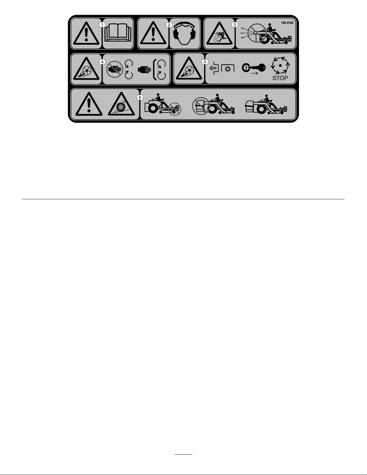
SafetyandInstructionalDecals..........................4
Setup........................................................................7
1PreparingtheMachine.....................................8
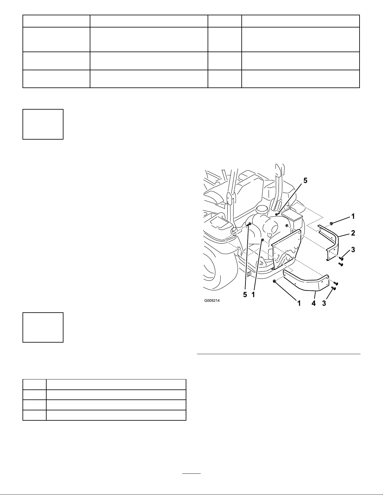
2InstallingtheSideBumpers..............................8
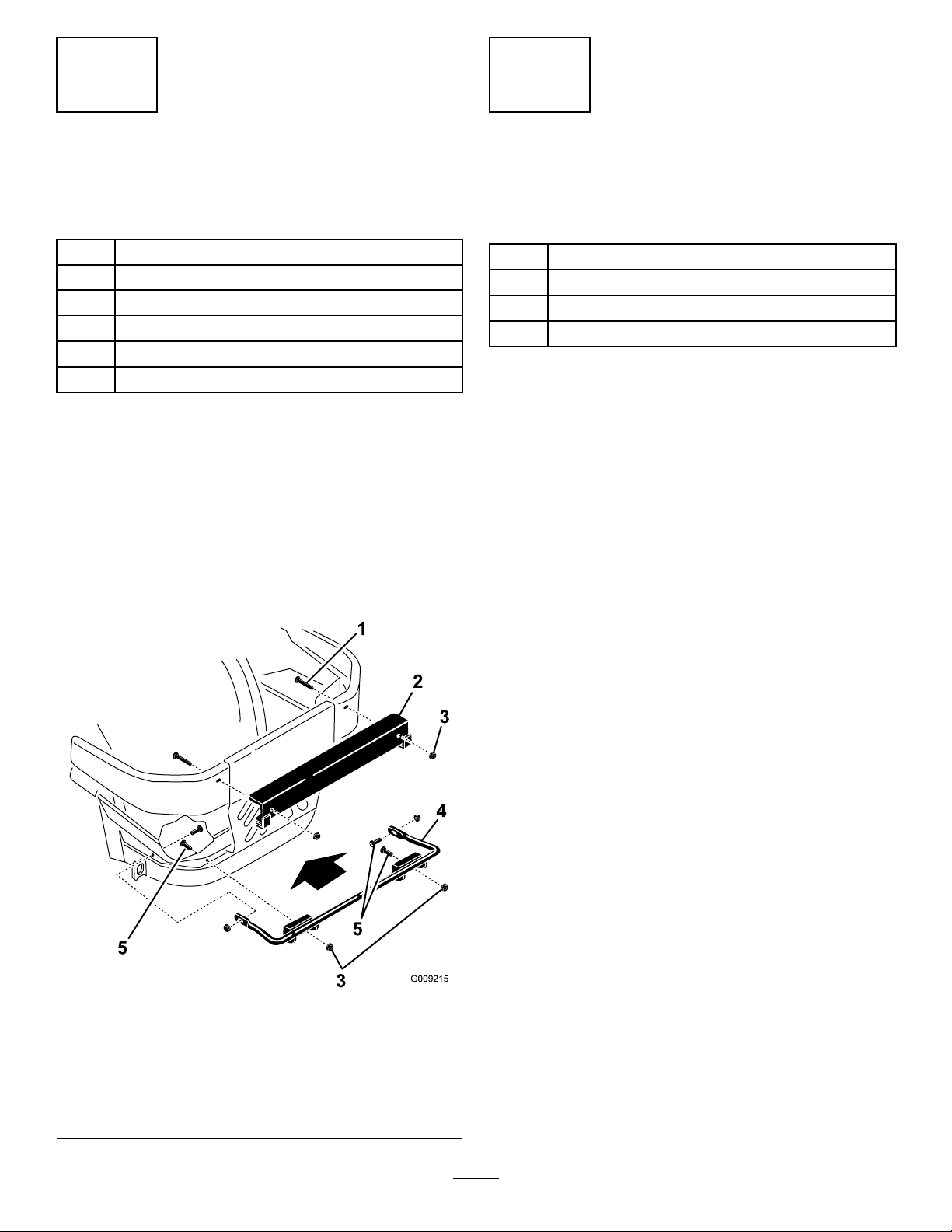
3InstallingtheBaggerMounting
Brackets..........................................................9
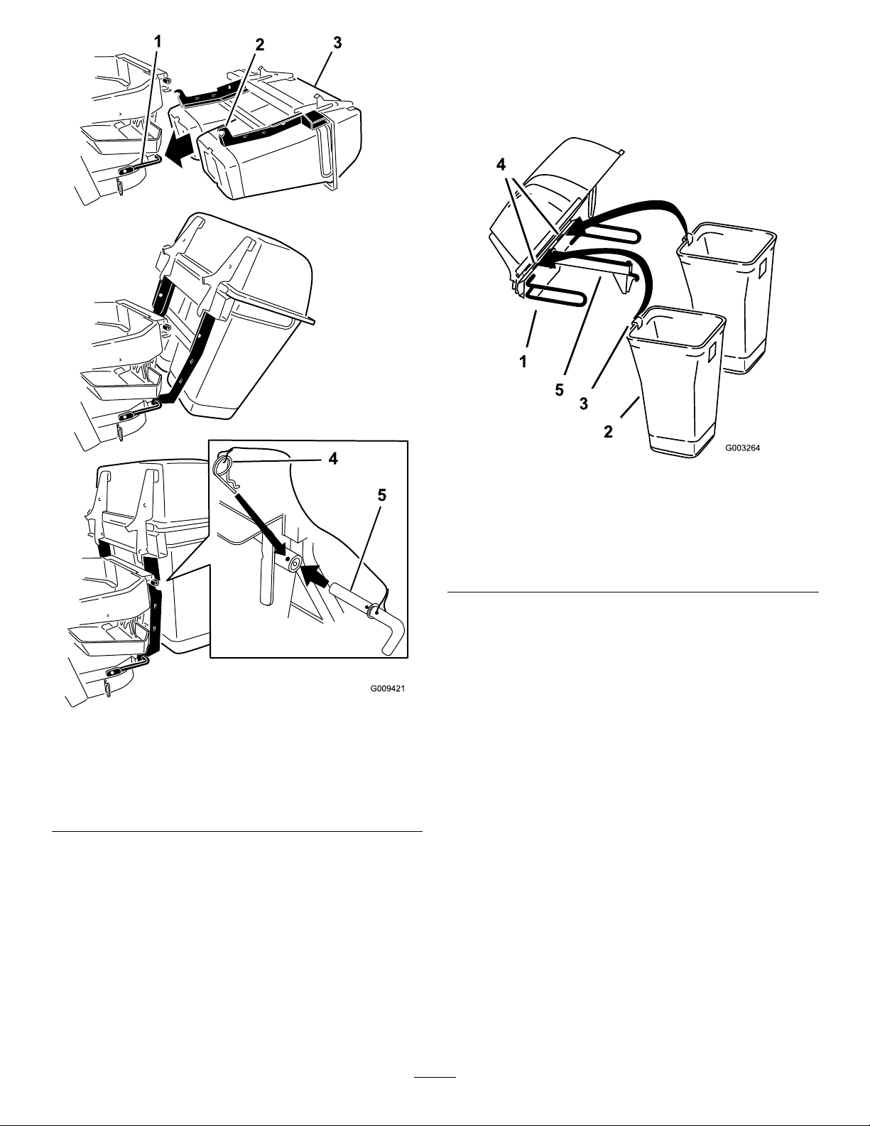
4InstallingtheHoodAssemblyand
Bags................................................................9
5InstallingtheMuferDeector.........................11
6RoutingtheBlowerBeltintotheBlower
Assembly......................................................12
7InstallingtheBlowerAssembly.......................12
8InstallingtheDischargeTubes.......................14
9InstallingtheBeltCover.................................19
10InstallingtheWeights...................................19
11InstallingtheBumpers..................................21
12AdjustingtheParkingBrake.........................22
13CheckingtheTirePressure..........................22
Operation................................................................23
PositioningtheAdjustableBafe.......................23
EmptyingtheGrassBags.................................23
ClearingObstructionsfromtheBagger
System..........................................................24
RemovingtheBagger.......................................24
UsingtheGrassDeector.................................25
TransportingtheMachine.................................25
OperatingTips.................................................25
Maintenance...........................................................27
RecommendedMaintenanceSchedule(s)...........27
CleaningtheHoodScreen................................27
CleaningtheBaggerandBags.........................27
InspectingtheBlowerBelt................................27
ReplacingtheBlowerBeltfor60-and72-inch
Machines......................................................27
ReplacingtheBlowerBeltfor48-and52-inch
Machines......................................................28
CheckingandAdjustingtheBlower
Latch.............................................................29
GreasingtheIdlerArm......................................29
InspectingtheBagger.......................................30
InspectingtheMowerBlades............................30
InstallingtheMowerBlades..............................30
ReplacingtheGrassDeector..........................30
Storage...................................................................31
Troubleshooting......................................................32
Safety
•Becomefamiliarwiththesafeoperationofthe
equipment,withtheoperatorcontrols,andsafety
signs.
•Useextracarewithgrasscatchersorother
attachments.Thesecanchangetheoperating
characteristicsandthestabilityofthemachine.
•Followthemanufacturer'srecommendations
foraddingorremovingwheelweightsor
counterweightstoimprovestability.
•Donotuseagrasscatcheronsteepslopes.A
heavygrasscatchercouldcauselossofcontrol
oroverturnthemachine.
•Slowdownanduseextracareonhillsides.Be
suretotravelintherecommendeddirectionon
hillsides.Turfconditionscanaffectthestabilityof
themachine.Useextremecautionwhileoperating
neardrop-offs.
•Keepallmovementonslopesslowandgradual.
Donotmakesuddenchangesinspeed,direction,
orturning.
•Thegrasscatchercanobstructtheviewtothe
rear.Useextracarewhenoperatinginreverse.
•Usecarewhenloadingorunloadingthemachine
intoatrailerortruck.
•Neveroperatewiththedischargedeectorraised,
removedoraltered,unlessusingagrasscatcher.
•Keephandsandfeetawayfrommovingparts.Do
notmakeadjustmentswiththeenginerunning.
•DisengagethePTO,movethemotion-control
leverstotheNEUTRAL-LOCKposition,engagethe
parkingbrake,shutofftheengine,removethekey,
andwaitforallmovingpartstostopbeforeleaving
theoperatingposition.
•Chockthewheelsbeforeemptyingthegrass
catcheroruncloggingthechute.
•Ifyouremovethegrasscatcher,besuretoinstall
anydischargedeectororguardthatmighthave
beenremovedtoinstallthegrasscatcher.Donot
operatethemowerwithouteithertheentiregrass
catcherorthegrassdeectorinplace.
•Shutofftheenginebeforeremovingthegrass
catcheroruncloggingthechute.
•Donotleavegrassinthegrasscatcherfor
extendedperiodsoftime.
•Grasscatchercomponentsaresubjecttowear,
damageanddeterioration,whichcouldexpose
youtomovingpartsorallowobjectstobethrown.
Frequentlycheckcomponentsandreplacewith
themanufacturer'srecommendedparts,when
necessary.
3

TowingSafety
•Donotattachtowedequipmentexceptatthehitch
point.
•Followtheattachmentmanufacturer's
recommendationforweightlimitsfortowed
equipmentandtowingonslopes.
•Neverallowchildrenorothersinorontowed
equipment.
•Onslopes,theweightofthetowedequipmentmay
causelossoftractionandlossofcontrol.Reduce
towedweightandslowdown.
•Stoppingdistanceincreaseswiththeweightofthe
towedload.Travelslowlyandallowextradistance
tostop.
•Makewideturnstokeeptheattachmentclearof
themachine.
•Donottowaloadthatweighsmorethanthe
towingmachine.
SafetyandInstructionalDecals
Safetydecalsandinstructionsareeasilyvisibletotheoperatorandarelocatednearanyarea
ofpotentialdanger.Replaceanydecalthatisdamagedorlost.
decal1-653558
1-653558decal98-5954
98-5954
decal103-3508
103-3508
decal106-0871
106-0871
4

decal106-3339
106-3339
decal106-5517
106-5517
1.Warning—donottouchthehotsurface.
decal126-4659
126-4659
1.Warning—hotpulley;allowtocool.
decal126-9451
126-9451
1.Thrownobjectshazard—Donotruntheblowerwithoutthe
entirecollectionsysteminstalledandlatched.
2.Warning–ReadtheOperator’smanualaboutcounterbalance
weightinstallation.
3.Lossoftractionandsteeringorreducedstabilityhazard–Ez
Vaccounterbalanceweight(s)installedwithouttheEzVac
maycauselossoftractionandsteeringcontrol.TheEzVac
installedwithouttheEzVaccounterbalanceweight(s)can
causereducedstability.Installweight(s)onlywhentheEz
Vacisinstalled.
decal126-9595
126-9595
1.Rotationindicator
2.Impeller/RotatingBladeshazard-Keephandsawayfrom
movingparts.Keepallsafetydevicesinplaceandworking.
Donotreachintotheblowerunlesstherotationindicator
hasstopped.DisengagethePTO,shutofftheengine,
removethekey,andwaitforallmovingpartstostop.
decal133-8061
133-8061
5

decal136-4164
136-4164
1.Warning—readtheOperator’sManual.4.Cutting/dismembermenthazard,impeller—keepawayfrom
movingparts;keepallguardsandcoversinplace.
2.Warning—hearingprotectionmustbeworn.5.Cutting/dismembermenthazard,impeller—disengagethe
PTO,removethekey,andwaitforallmovingpartstostop.
3.Thrownobjecthazard—donotoperatetheblowerwithoutthe
entiresysteminstalledandlatched.
6.Warning;lossoftraction—donotoperatewithonly
counterbalanceweightsinstalled;donotoperatewithonly
E-ZVacinstalled;operateonlywithbothE-ZVacand
counterbalanceweightsinstalled.
6

Setup
LooseParts
Usethechartbelowtoverifythatallpartshavebeenshipped.
ProcedureDescriptionQty.Use
1Nopartsrequired–Preparethemachine.
Leftbumper1
Rightbumper1
Carriagebolt(3/8x1-1/4inches)2
2Flangenut(3/8inch)6
Installthesidebumpers.
Uppermountingbracket1
Lowermountingbracket1
Carriagebolt(3/8x1-1/4inches)4
Carriagebolt(1/2x2–1/2inches)2
Flangenut(3/8inch)4
3
Flangenut(1/2inch)2
Installthebaggermountingbrackets.
Hoodassembly1
Bag(48-inchand52-inchdecks)2
Bag(60-inchand72-inchdecks)3
4Pinandhairpin-cotterassembly2
Installthehoodassemblyandbags.
Muferdeector1
Flangenut(3/8inch)2
5Carriagebolt(3/8x1-1/4inches)2
Installthemuferdeector.
6Blowerbelt(fromBlowerandDriveKit)1Routetheblowerbeltintotheblower
assembly.
Blowerassembly(fromtheBlowerand
DriveKit)1
7Spring(fromtheBlowerandDriveKit)1
Installtheblowerassembly.
Uppertube1
Lowertube1
Bolt(#10x3/4inches)3
Locknut(#10)3
8
Washer(7/32inch)3
Installthedischargetubes.
9Beltcover(fromBlowerandDriveKit)1Installthebeltcover.
Casterweight(ifneeded)2
Clevispin2
Hairpincotter2
Lockwasher(3/8inch)6
Weight-mountbracket1
Bolt(3/8x1-1/2inches)6
Flatwasher(3/8inch)6
Carriagebolt(5/16x3/4inch)3
Flangenut(5/16inch)3
Frontweight(48-inch,52-inch,and
60-inchdecks)3
Frontweight[72-inchdecks(serial
number406294344andbelow)]1
10
Frontweight[72-inchdecks(serial
number406294345andabove)]2
Installtheweights.
7

ProcedureDescriptionQty.Use
Bumper2
Spacer2
11Locknut(5/16inch)2
Installthebumpers(formachineswith
MyRide™suspensionsystem).
12Nopartsrequired–Adjusttheparkingbrake.
13Nopartsrequired–Checkthetirepressure.
Note:Determinetheleftandrightsidesofthemachinefromthenormaloperatingposition.
1
PreparingtheMachine
NoPartsRequired
Procedure
Performthefollowingproceduretopreparethe
machineforattachingtheblowerandnishingkit.
1.DisengagethePTO,movethemotion-control
leverstotheNEUTRAL-LOCKEDposition,and
engagetheparkingbrake.
2.Shutofftheengine,removethekey,andwait
forallmovingpartstostopbeforeleavingthe
operatingposition.
3.Repairallbentordamagedareasofmachine
deckandreplaceanymissingparts.
4.Cleanthemachineofanydebrisonthemachine
deckorrearpartofthemachinetoease
installation.
2
InstallingtheSideBumpers
Partsneededforthisprocedure:
1Leftbumper
1Rightbumper
2Carriagebolt(3/8x1-1/4inches)
6Flangenut(3/8inch)
Procedure
1.Removethenutsandboltsholdingtheside
bumperstothemachine(Figure5).
Note:Discardallnutsandonlythe1bolt
removedfromeachside.
2.Installthenewleftandrightsidebumperswith2
carriagebolts(3/8x1-1/4inches),4previously
removedcarriagebolts,and6angenuts(3/8
inch)asshowninFigure5.
g009214
Figure5
1.Flangenut(3/8inch)4.Leftbumper
2.Rightbumper5.Bolt(3/8x1-1/4inches)
3.Useexistingbolts
8

3
InstallingtheBagger
MountingBrackets
Partsneededforthisprocedure:
1Uppermountingbracket
1Lowermountingbracket
4Carriagebolt(3/8x1-1/4inches)
2Carriagebolt(1/2x2–1/2inches)
4Flangenut(3/8inch)
2Flangenut(1/2inch)
Procedure
1.Installthelowermountingbrackettothe
machineframewith4carriagebolts(3/8x1-1/4
inches)and4angenuts(3/8inch)asshown
inFigure6.
2.Installtheuppermountingbrackettotheleftand
rightsidebumperswith2carriagebolts(1/2x
2-1/2inches)and2angenuts(1/2inch)as
showninFigure6.
g009215
Figure6
1.Carriagebolt(1/2x2-1/2
inches)
4.Lowermountingbracket
2.Uppermountingbracket5.Carriagebolt(3/8x1-1/4
inches)
3.Flangenut(1/2inch)6.Flangenut(3/8inch)
4
InstallingtheHood
AssemblyandBags
Partsneededforthisprocedure:
1Hoodassembly
2Bag(48-inchand52-inchdecks)
3Bag(60-inchand72-inchdecks)
2Pinandhairpin-cotterassembly
Procedure
1.Positionthehoodassemblyonitsback.
2.Slidehooksontothelowermountingbracket
(Figure7).
3.Rotatethehoodassemblyuponthelower
baggermountingbracket(Figure7).
4.Aligntheholeinthebaggerwiththeupper
mountingbracket(Figure7).
5.Installthepinandsecureitwiththehairpin
cotteronbothsides(Figure7).
9

g009421
Figure7
1.Lowermountingbracket4.Hairpincotterconnected
tolanyard
2.Hook5.Pinconnectedtolanyard
3.Hoodassembly
6.Installthebagtabintothenotchinthehood
assembly(Figure8orFigure9).
Note:Dothisforallthebags.
Note:Thebagswillrestonthebaggerframe.
g003264
Figure8
Twinbaggershown
1.Hoodassembly4.Notch
2.Bag5.Baggerframe
3.Bagtab
10

g009301
Figure9
Triplebaggershown
1.Hoodassembly4.Notch
2.Bag5.Baggerframe
3.Bagtab
7.Lowerthebaggerhoodoverthebags(Figure
10orFigure11).
g003268
Figure10
Twinbaggershown
1.Hood3.Baggerlatch
2.Bag4.Latchhook
g003265
Figure11
Triplebaggershown
1.Hood3.Baggerlatch
2.Bag4.Latchhook
8.Positionthebaggerlatchunderthelatchhook
(Figure12).
9.Pushdownonbaggerlatchuntilitlocksinto
place(Figure12).
g003267
Figure12
1.Baggerlatch2.Latchhook
11

5
InstallingtheMufer
Deector
Partsneededforthisprocedure:
1Muferdeector
2Flangenut(3/8inch)
2Carriagebolt(3/8x1-1/4inches)
Procedure
Installthemuferdeectortothesideofthebagger
frame(Figure13).
Note:Ensurethemuferdeectorispositionedover
thetailpipeofthemufer.
g009417
Figure13
1.Muferdeector3.Carriagebolt(3/8x1-1/4
inches)
2.Flangenut(3/8inch)
6
RoutingtheBlowerBelt
intotheBlowerAssembly
Partsneededforthisprocedure:
1Blowerbelt(fromBlowerandDriveKit)
Procedure
1.For60-and72-inchmachinedecks,installthe
beltaroundtheblowerpulley(Figure14).
g003398
Figure14
Blowerfor60-and72-inchmachines
1.Idlerpulley4.Springpeg
2.Machinedeckpulley5.Belt
3.Spring6.Blowerpulley
2.For48-and52-inchmachines,loosenthe
belt-guidebolt(Figure15).
3.Installthebeltaroundtheblowerpulleyand
xed-idlerpulley(Figure15).
4.Tightenthebelt-guidebolt.
g003454
Figure15
1.Idlerpulley5.Belt
2.Machinedeckpulley6.Belt-guidebolt
3.Spring7.Fixed-idlerpulley
4.Springpeg8.Blowerpulley
12

7
InstallingtheBlower
Assembly
Partsneededforthisprocedure:
1Blowerassembly(fromtheBlowerandDriveKit)
1Spring(fromtheBlowerandDriveKit)
Procedure
WARNING
Anuncovereddischargeopeningcouldallow
thelawnmowertothrowobjectsatyouor
bystanders,resultinginseriousinjury.Also,
contactwiththebladecouldoccur.
•Neveroperatethelawnmowerunlessyou
installacoverplate,amulchplate,ora
grasschuteandcatcher.
•Makesurethatthegrassdeectoris
installedwhenthegrasschuteandcatcher
areremoved.
1.Removethesidedischargechutefromthe
mowerdeck(Figure16).
Note:Saveallthehardwareandtheside
dischargechute.Installthesidedischargechute
whenthebaggerandblowerareremoved.
g002519
Figure16
1.Bolt5.Springinstalled
2.Spacer6.Grassdeector
3.Locknut7.Lendofspring(place
behindthedeckedge
beforeinstallingthebolt)
4.Spring8.J–hookendofspring
2.Slidetheblower-assemblypegintothepivot
hole(Figure17orFigure18).
g009420
Figure17
48-and52-inchmowerdeckshown
1.Blowerassembly3.Pivothole
2.Mowerdeck4.Blower-assemblypeg
13

g009220
Figure18
60-and72-inchmowerdeckshown
1.Blowerassembly3.Pivothole
2.Mowerdeck4.Blower-assemblypeg
3.Closetheblowerassemblytoseeifthelatches
areadjustedcorrectly.
Note:Loosenortightentheboltsothelatches
rmlyholdtheblowerassemblyagainstthe
mowerdeck,butcanbereleasedbyhand
(Figure19).
g003400
Figure19
1.Latch3.Blowerassembly
2.Bolt
4.InstallthespringasshowninFigure20.
Note:Makesurethatthehooksareinthe
correctposition.
g003638
Figure20
1.Spring-loadedidlerpulley3.Long-hookend
2.Short-hookend
5.Pullthespring-loadedidlerpulleybackand
routethebeltaroundthemower-deckpulley.
Note:Ensurethatthebeltisroutedaroundthe
blowerpulleyscorrectly(Figure21).
g003399
Figure21
1.Mower-deckpulley3.Blower
2.Spring-loadedidlerpulley
14

8
InstallingtheDischarge
Tubes
Partsneededforthisprocedure:
1Uppertube
1Lowertube
3Bolt(#10x3/4inches)
3Locknut(#10)
3Washer(7/32inch)
Procedure
Important:Makesurethatthemowerdeckisin
thelowestheight-of-cutpositionwhileinstalling
thedischargetubes.
Note:Remembertoreplacethegrassdeectorwhen
thebaggerisremovedfromthemachine.Referto
ReplacingtheGrassDeector(page30).
1.DisengagethePTOandengagetheparking
brake.
2.Shutofftheengine,removethekey,andwait
forallmovingpartstostopbeforeleavingthe
operatingposition.
3.Lowerthemachinedecktothelowest
height-of-cutposition.
4.Removethebagsforviewingthetubeunder
thehood.
5.Installtheuppertubeintothebaggeropening
andpullitbackoutsothattherubbersealis
protrudingout(Figure22orFigure23).
g009304
Figure22
Twinbaggershown
1.Uppertube3.Baggerhood
2.Baggeropening
g009302
Figure23
Triplebaggershown
1.Uppertube3.Baggerhood
2.Baggeropening
6.Withthehoodinthedownposition,measurethe
distancethetubeisinsidethehood.
Measurefromthehoodplatetotheedgeofthe
tubeasshowninFigure24.
Note:Thisdistanceneedstobe19mm(3/4
inch).
15

g003388
Figure24
1.Hoodplate4.19mm(3/4inch)
2.Uppertube5.Edgeoftube
3.Hoodinthedownposition
7.Oncethe19mm(3/4inch)measurementhas
beenachieved,marktheuppertubeonthe
outsidewheretherubbersealprotrudesout
(Figure25).
Note:Thisismarkedtoensurethecorrect
positionfortheuppertubewhendrillingthe
holesandconnectingtheupperandlowertubes.
Note:Therubbersealmustprotrudeoutfrom
thebaggerhood.
g003393
Figure25
1.Uppertube3.Baggerhood
2.Rubbersealprotrudingout4.Markhereagainstthe
rubberseal
8.Installthelowertubeintotheuppertube(Figure
26).
g003424
Figure26
1.Lowertube2.Uppertube
9.Slidethelowertubeontothebootandlatch
themtogether(Figure27orFigure28).
Note:Thereisalatchonthetopandbottom
oftheblowerhousing.
16

g003449
Figure27
Twinbaggershown
1.Blowerassembly3.Latch(twinbaggershown)
2.Lowertube
g003423
Figure28
Triplebaggershown
1.Blowerassembly3.Latch(triplebagger
shown)
2.Lowertube
10.Makesurethatthemachinedeckisinthelowest
height-of-cutposition.
11.ChecktomakesurethatthemarkfromFigure
25isstillinplace.
12.Usingthe3holesorindentationsintheupper
tubeasatemplate,drill3holes(7/32inch
diameter)wheretheupperandlowertubesjoin
together(Figure29).
17

g003390
Figure29
1.Baggerhood4.Lowertube
2.Uppertube5.Blowerassembly
3.Drill7/32inchdiameter
holeshere(useuppertube
asatemplate)
13.Removethelowertubefromtheblower.
14.Jointheupperandlowertubeswith3bolts(#10
x3/4inches),3atwashers(7/32inch),and3
locknuts(#10)asshowninFigure30.
g003392
Figure30
1.Lowertube4.Locknut(#10)
2.Uppertube5.Bolt(#10x3/4inches)
3.Flatwasher(7/32inch)
15.Installthelowertubeontotheblowerhousing
andsecureitwiththelatches.
16.Installthebagsontothebagger.
18

9
InstallingtheBeltCover
Partsneededforthisprocedure:
1Beltcover(fromBlowerandDriveKit)
Procedure
1.Lowerthemowerdecktothelowestheight-of-cut
position.
2.Installthenewbeltcoversothatthenotcheson
bothsidesgooverthebelt-coversupportsand
securethelatch(Figure31orFigure32).
g009305
Figure31
48-and52-inchbaggershown
1.Beltcover3.Notch
2.Belt-coversupport
g009303
Figure32
60-and72-inchbaggershown
1.Beltcover3.Notch
2.Belt-coversupport
10
InstallingtheWeights
Partsneededforthisprocedure:
2Casterweight(ifneeded)
2Clevispin
2Hairpincotter
6Lockwasher(3/8inch)
1Weight-mountbracket
6Bolt(3/8x1-1/2inches)
6Flatwasher(3/8inch)
3Carriagebolt(5/16x3/4inch)
3Flangenut(5/16inch)
3Frontweight(48-inch,52-inch,and60-inchdecks)
1Frontweight[72-inchdecks(serialnumber406294344
andbelow)]
2Frontweight[72-inchdecks(serialnumber406294345
andabove)]
Procedure
TocomplywithANSI/OPEIB71.4-2012Standard,add
weightstothemachine.
19

CAUTION
Thebaggeraddsalotofweighttotherear
ofthemachineandmaycauseanunstable
conditionwhichcouldresultinalossof
control.
Thefollowingtableshowswhatweightsareused
whenabaggerisinstalled.
Frontweights
used
Casterweights
used
48-inchmachine
deckwithbagger
30
52-inchmachine
deckwithbagger
30
60-inchmachine
deckwithbagger
32
72-inchmachine
deckwithbagger
(serialnumber
406294344and
below)
12
72-inchmachine
deckwithbagger
(serialnumber
406294345and
above)
22
1.Installcasterweightsonthefrontcasterswitha
clevispinandahairpincotter(Figure33).
2.Installthenutontoeachtapboltandinstallthe
tapboltsintoeachweight(Figure33).
3.Tightenthetapboltsoittouchestheframeand
thentightenthejamnutagainsttheweight.
g009224
Figure33
1.Tapbolt(3/8x1-1/2
inches)
4.Hairpincotter
2.Nut(3/8inch)5.Clevispin
3.Casterweight6.Installthetapboltagainst
theframeandtightenthe
nut.
4.Installtheweight-mountbracketunderthe
footrestwith2carriagebolts(5/16x3/4inch)
and2angenuts(5/16inch)asshowninFigure
34).
g009226
Figure34
1.Carriagebolt(5/16x3/4
inch)
3.Flangenut(5/16inch)
2.Weight-mountbracket
5.Installthefrontweightsontopofthefootrest
(Figure35).
6.Securethefrontweightsontopofthefootrest
andtotheweight-mountbracketwith6bolts
(3/8x1inch),6lockwashers(3/8inch),3ange
20
This manual suits for next models
2
Table of contents
Other Toro Lawn Mower Accessories manuals

Toro
Toro Recycler 59197 User manual

Toro
Toro 136-5850 User manual

Toro
Toro 74254 User manual

Toro
Toro Reelmaster 5010- H User manual

Toro
Toro 13-32G Wheel Horse User manual

Toro
Toro 133-0575 User manual

Toro
Toro 145-3495 User manual

Toro
Toro 140-1559 User manual

Toro
Toro Reelmaster 2000 Series User manual

Toro
Toro 30555 User manual