Toro 78593 User manual

FormNo.3427-980RevB
BlowerKit
GrandStand®MultiForceMower
ModelNo.78593—SerialNo.403400000andUp
Registeratwww.Toro.com.
OriginalInstructions(EN)*3427-980*B

WARNING
CALIFORNIA
Proposition65Warning
Useofthisproductmaycauseexposure
tochemicalsknowntotheStateof
Californiatocausecancer,birthdefects,
orotherreproductiveharm.
Introduction
Thisblowerisintendedtobeusedbyprofessional,
hiredoperators.Itisprimarilydesignedtousewind
powertoquicklyclearlargeareasofunwanteddebris
onwell-maintainedlawns,parks,golfcourses,sports
elds,andoncommercialgrounds.Usingthisproduct
forpurposesotherthanitsintendedusecouldprove
dangeroustoyouandbystanders.
Readthisinformationcarefullytolearnhowtooperate
andmaintainyourproductproperlyandtoavoid
injuryandproductdamage.Youareresponsiblefor
operatingtheproductproperlyandsafely.
Visitwww.T oro.comformoreinformation,including
safetytips,trainingmaterials,accessoryinformation,
helpndingadealer,ortoregisteryourproduct.
Wheneveryouneedservice,genuineToroparts,or
additionalinformation,contactanAuthorizedService
DealerorT oroCustomerServiceandhavethemodel
andserialnumbersofyourproductready.Figure1
identiesthelocationofthemodelandserialnumbers
ontheproduct.Writethenumbersinthespace
provided.
Important:Withyourmobiledevice,youcan
scantheQRcodeontheserialnumberdecal(if
equipped)toaccesswarranty,parts,andother
productinformation.
g246145
Figure1
1.Locationofthemodelandserialnumbers
ModelNo.
SerialNo.
Thismanualidentiespotentialhazardsandhas
safetymessagesidentiedbythesafety-alertsymbol
(Figure2),whichsignalsahazardthatmaycause
seriousinjuryordeathifyoudonotfollowthe
recommendedprecautions.
g000502
Figure2
1.Safety-alertsymbol
Thismanualuses2wordstohighlightinformation.
Importantcallsattentiontospecialmechanical
informationandNoteemphasizesgeneralinformation
worthyofspecialattention.
©2019—TheToro®Company
8111LyndaleAvenueSouth
Bloomington,MN554202
Contactusatwww.Toro.com.
PrintedintheUSA
AllRightsReserved

Contents
Safety.......................................................................3
GeneralSafety...................................................3
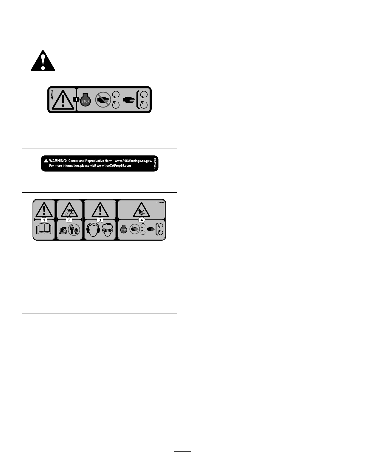
SafetyandInstructionalDecals..........................4
Setup........................................................................5
1PreparingtheMachine.....................................5
2InstallingtheWheelWeightKit
(Optional)........................................................5
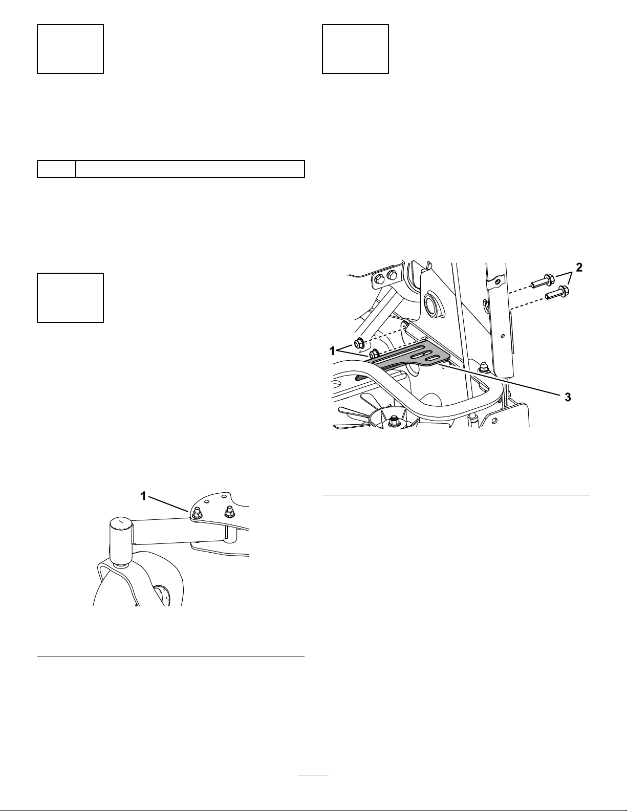
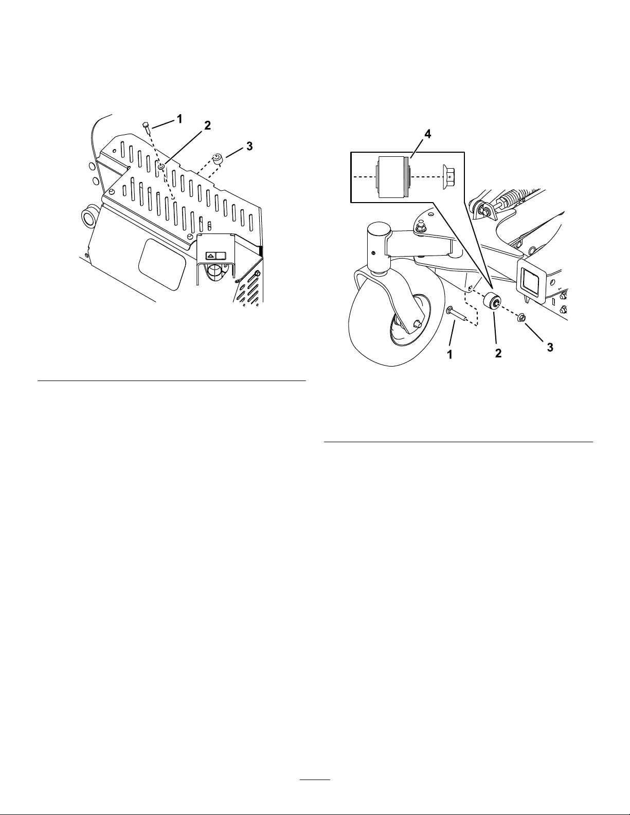
3PositioningtheCasterWheels.........................6
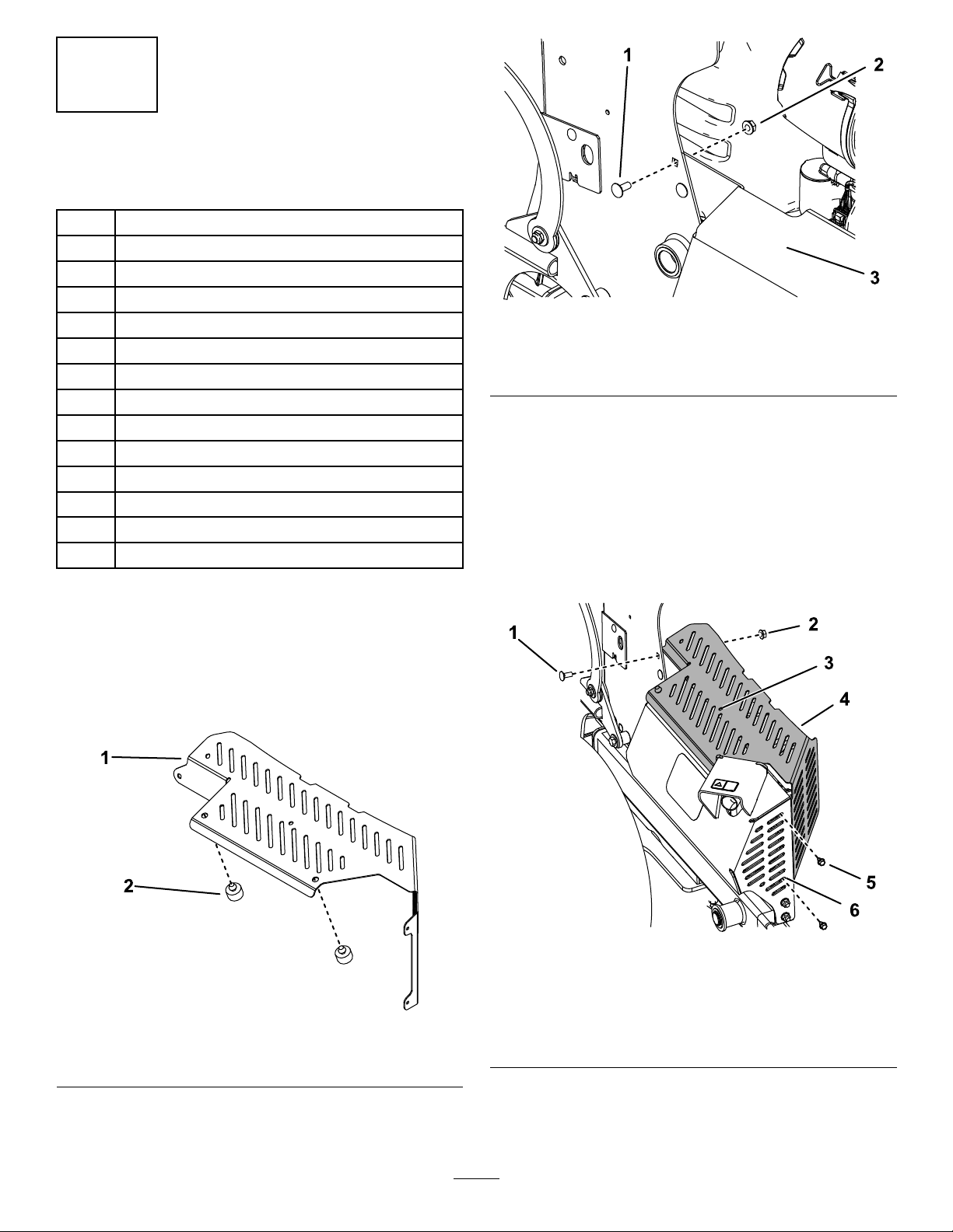
4RemovingtheRightFanGuard........................6
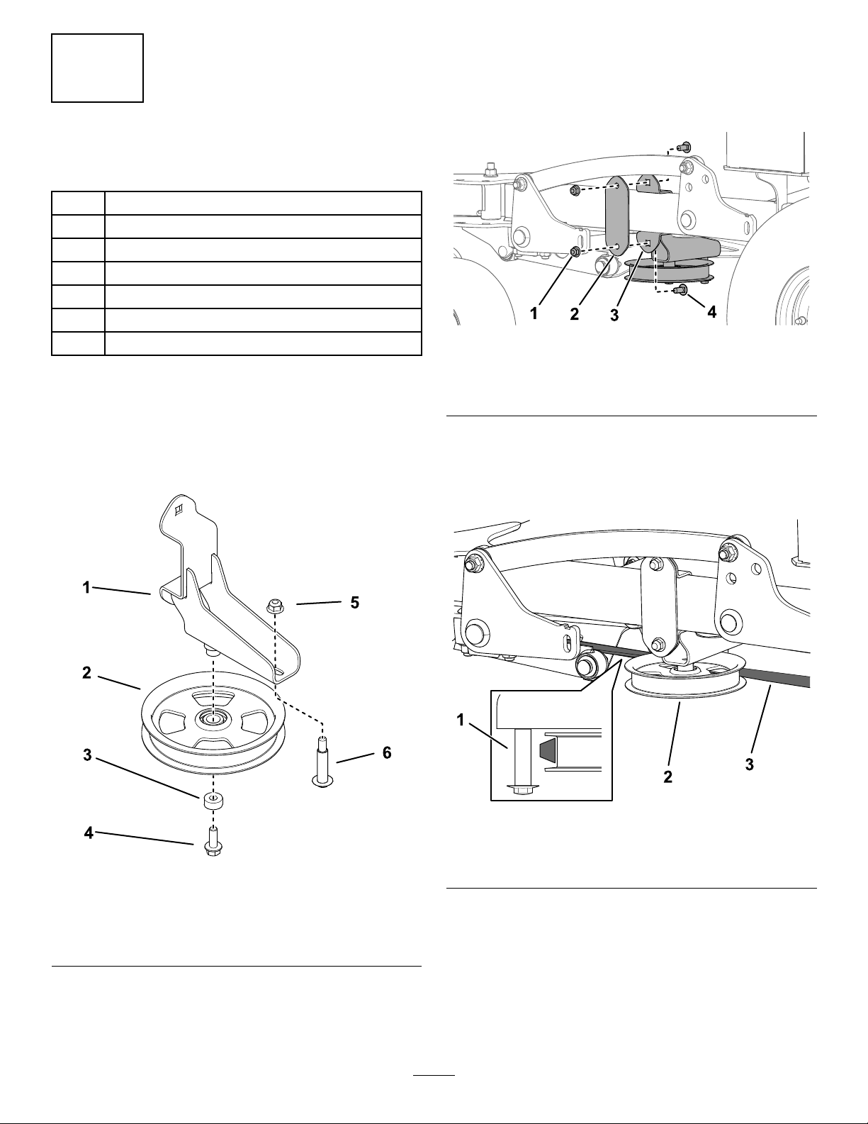
5InstallingtheIdlerPulley..................................7
6InstallingtheBlower.........................................7
Operation................................................................12
OperationSafety..............................................12
OperatingtheBlower........................................12
UsingtheKickstand..........................................12
RemovingtheBlower........................................14
OperatingTips.................................................17
Maintenance...........................................................18
MaintenanceSafety..........................................18
CheckingtheBelts............................................18
ReplacingtheBlowerBelt.................................18
ReplacingtheClutchBelt..................................19
CheckingtheHydraulicHoses..........................19
RemovingDebrisfromtheMachine..................19
Safety
GeneralSafety
Thisproductiscapableofthrowingobjects.Always
followallsafetyinstructionstoavoidseriouspersonal
injury.
•Readandunderstandthecontentsofthis
Operator’sManualbeforestartingtheengine.
•Useyourfullattentionwhileoperatingthe
machine.Donotengageinanyactivitythat
causesdistractions;otherwise,injuryorproperty
damagemayoccur.
•Donotputyourhandsorfeetnearmoving
componentsofthemachine.
•Donotoperatethemachinewithoutallguards
andothersafetyprotectivedevicesinplaceand
workingonthemachine.
•Keepclearofanydischargeopening.Keep
bystandersandpetsasafedistanceawayfrom
themachine.
•Keepchildrenoutoftheoperatingarea.Never
allowchildrentooperatethemachine.
•Stopthemachine,shutofftheengine,andremove
thekeybeforeservicing,fueling,orunclogging
themachine.
Improperlyusingormaintainingthismachinecan
resultininjury.Toreducethepotentialforinjury,
complywiththesesafetyinstructionsandalways
payattentiontothesafety-alertsymbol,which
meansCaution,Warning,orDanger—personalsafety
instruction.Failuretocomplywiththeseinstructions
mayresultinpersonalinjuryordeath.
3

SafetyandInstructional
Decals
Safetydecalsandinstructionsare
easilyvisibletotheoperatorandare
locatednearanyareaofpotential
danger.Replaceanydecalthatis
damagedormissing.
decal119-0217
119-0217
1.Warning—stoptheengine;stayawayfrommovingparts;
keepallguardsandshieldsinplace.
decal133-8061
133-8061
decal137-3999
137-3999
1.Warning—readthe
Operator’sManual.
3.Warning—wearhearing
andeyeprotection.
2.Thrownobject
hazard—keepbystanders
awayfromthemachine.
4.Cutting/dismemberment
hazardofhands—shut
offtheengine;keep
handsawayfrommoving
parts;keepallguardsand
shieldsinplace.
4

Setup
LooseParts
Usethechartbelowtoverifythatallpartshavebeenshipped.
ProcedureDescriptionQty.Use
1Nopartsrequired–Preparethemachine.
2WheelWeightKit(soldseparately)1InstalltheWheelWeightKit(optional).
3Nopartsrequired–Positionthecasterwheels.
4Nopartsrequired–Removethefanguard.
Idlerpulley1
Hex-angeheadbolt1
Spacer1
Mountingbracket1
Carriagebolt2
Nut3
5
Plate1
Installtheidlerpulley.
Blowerassembly1
Bushingassembly2
Carriagebolt(3/8x2-1/4inches)2
Locknut(3/8inch)2
Receiverhitch1
Heatshield1
Bumper2
Thread-formingscrew(1/4x1/2inch)2
Stopbracket1
Carriagebolt(3/8x1inch)1
Nut(3/8inch)1
Washer1
Spacer1
6
Thread-formingscrew(1/4x1-1/4inch)1
Installtheblower.
Important:InstalltheLowFlowHydraulicsKitonyourmachinebeforeinstallingthiskit.
1
PreparingtheMachine
NoPartsRequired
Procedure
1.Parkthemachineonalevelsurface.
2.LowertheA-frame.
3.DisengagethePTO,engagetheparkingbrake,
andmovethemotion-controlleversoutwardto
theNEUTRAL-LOCKposition.
4.Shutofftheengineandremovethekey.
5

2
InstallingtheWheelWeight
Kit(Optional)
Partsneededforthisprocedure:
1WheelWeightKit(soldseparately)
Procedure
Installingwheelweightscanimprovetractionon
themachinewhenusingtheblower;refertothe
InstallationInstructionsfortheWheelWeightKit.
3
PositioningtheCaster
Wheels
NoPartsRequired
Procedure
Forbothcasters,removethenutandbolt,movethe
castertothefrontposition,andinstallthenutandbolt
(Figure3).Torqueto91to113N∙m(67to83ft-lb).
g230693
Figure3
1.Nutandbolt
4
RemovingtheRightFan
Guard
NoPartsRequired
Procedure
1.Removethefueltank;refertotheOperator’s
Manualforthemachine.
2.Removeandretainthe2bolts,2nuts,andthe
rightfanguard(Figure4).
g246823
Figure4
1.Nut(3/8inch)3.Rightfanguard
2.Bolt(3/8x1-1/4inch)
3.Installtheboltsandnutsyouremovedand
torqueto41to49N∙m(30to36ft-lb).
4.Installthefueltank.
6

5
InstallingtheIdlerPulley
Partsneededforthisprocedure:
1Idlerpulley
1Hex-angeheadbolt
1Spacer
1Mountingbracket
2Carriagebolt
3Nut
1Plate
Procedure
1.Securetheidlerpulleytothemountingbracket
usingthehex-angeheadbolt,andspacer
(Figure5).T orquetheboltto37to45N∙m(27
to33ft-lb).
g294691
Figure5
1.Mountingbracket4.Hex-angeheadbolt
2.Idlerpulley5.Nut
3.Spacer6.Shoulderbolt
2.Installtheshoulderbolttothemountingbracket
usinganut(Figure5).T orquetheboltto37to
45N∙m(27to33ft-lb).
3.Securethemountingbrackettotheleftmachine
frametube,betweentheplatesweldedtothe
tube,usingtheplate,2carriagebolts,and2
nuts(Figure6).T orquetheboltsto37to45N∙m
(27to33ft-lb).
g293527
Figure6
1.Nut(2)3.Mountingbracket
2.Plate4.Carriagebolt
4.Routethebelttotheidlerpulley(Figure7).
Important:Ensurethatthewidesideofthe
beltcontactsthepulleyasshowninFigure7.
Usetheshoulderboltasaguideforthebelt.
g293529
Figure7
1.Shoulderbolt3.Belt
2.Idlerpulley
7

6
InstallingtheBlower
Partsneededforthisprocedure:
1Blowerassembly
2Bushingassembly
2Carriagebolt(3/8x2-1/4inches)
2Locknut(3/8inch)
1Receiverhitch
1Heatshield
2Bumper
2Thread-formingscrew(1/4x1/2inch)
1Stopbracket
1Carriagebolt(3/8x1inch)
1Nut(3/8inch)
1Washer
1Spacer
1Thread-formingscrew(1/4x1-1/4inch)
Procedure
1.Removetheair-cleanercoverandlter;referto
theOperator’sManualforthemachine.
2.Installthe2bumpersontheheatshield(Figure
8).
g256852
Figure8
1.Heatshield2.Bumper
3.Removethetopcarriageboltandnutsecuring
themuferguardtothemachine(Figure9).
g246215
Figure9
1.Carriagebolt3.Muferguard
2.Nut
4.Looselyinstalltheheatshieldoverthemufer
guard,withthetabsinsidethemuferguardand
totheinsideoftheconsoletower,usingthe2
thread-formingbolts(1/4x1/2inch)andthe
carriageboltandnutyouremovedpreviously
(Figure10).
Important:Tominimizedebrisbuildupon
themufer,installtheheatshieldonthe
machinewhenusingtheblower.
g256853
Figure10
1.Carriagebolt4.Heatshield
2.Nut5.Thread-formingbolt—1/4
x1/2inch(2)
3.Drillhere.6.Tab(insidemuferguard)
8

5.Usingthecenterholeintheheatshieldasa
template,drillahole(7/32inch)intothemufer
guard(Figure10).
6.Usethethread-formingbolt(1/4x1-1/4inch)
andwashertoinstallthespacerbetweenthe
heatshieldandmuferguard(Figure11).
g256854
Figure11
1.Thread-formingbolt(1/4x
1-1/4)
3.Spacer
2.Washer
7.Torquethe3thread-formingboltsto4.5N∙m
(40in-lb).
Note:Donottorquethecarriageboltatthis
time.
8.Installtheair-cleanerlterandcover.
9.Useacarriagebolt(3/8x2-1/4inches)andnut
(3/8inch)toinstallthebushingassembliesto
themachine(Figure12).T orquetheboltto37
to45N∙m(27to33ft-lb).
Note:Therubberangeofthebushingshould
facetowardtheinsideofthemachineasshown
inFigure12.
g250302
Figure12
1.Carriagebolt(3/8x2-1/4
inches)
3.Nut(3/8inch)
2.Bushingassembly4.Rubberange
9

10.Useacarriagebolt(3/8x1inch)andalocknut
(3/8inch)toinstallthestopbrackettotheright
sideofthemachine(Figure13).Torquethebolt
to37to45N∙m(27to33ft-lb).
g250341
Figure13
1.Locknut(3/8inch)3.Carriagebolt(3/8x1inch)
2.Stopbracket
11.Removethehitchpinandcotterpinfromthe
A-frameanduseittoinstallthehitchreceiver
(Figure14).Ensurethatthepinlocksthe
A-frametothecrosstube.
g230752
Figure14
1.Hitchreceiver3.Cotterpin
2.Hitchpin
12.Movetheblowerinfrontofthemachineandlay
thebeltunderneaththemachinesothatitis
linedupwiththeclutch(Figure15).
g230767
Figure15
1.Blowerassembly3.Clutch
2.Belt
13.Placetheblowerassemblyforksontothe
bushingassemblies(Figure16).
g250511
Figure16
14.Routethebelttotheidlerpulley.
Important:Ensurethatthewidesideofthe
beltcontactsthepulleyasshowninFigure
17.Usetheshoulderboltasaguideforthe
belt.
10

g293529
Figure17
1.Shoulderbolt3.Belt
2.Idlerpulley
15.Installthebeltontotheclutch.Verifythatthe
beltisstillroutedontheblowerpulleysandis
seatedproperlyinthepulleygrooves.
Note:Youcanuseadriveratchet(1/2inch)to
movetheleftidlerpulleyfortheblower(Figure
18).
g231579
Figure18
1.Driveratchet2.Pulley
16.RaisetheblowerasdescribedinRaisingthe
Blower(page13).
17.Connectthehydraulichosestothe
quick-disconnectcouplingsontheLowFlow
HydraulicsKit.
WARNING
Hydraulicuidescapingunderpressure
canpenetrateskinandcauseinjury.
Fluidinjectedintotheskinmustbe
surgicallyremovedwithinafewhoursby
adoctorfamiliarwiththisformofinjury;
otherwise,gangrenemayresult.
•Ensurethatallhydraulic-uidhoses
andlinesareingoodconditionandall
hydraulicconnectionsandttingsare
tightbeforeapplyingpressuretothe
hydraulicsystem.
•Keepyourbodyandhandsawayfrom
pinholeleaksornozzlesthateject
high-pressurehydraulicuid.
•Usecardboardorpapertond
hydraulicleaks;neveruseyour
hands.
11

Operation
OperationSafety
•Themachineexceedsnoiselevelsof85dB(A)at
theoperator’sposition.Usehearingprotection
forprolongedexposuretoreducethepotentialof
permanenthearingdamage.
•Wearappropriateclothingincludingeyeprotection;
longpants;substantial,slip-resistantfootwear;
andhearingprotection.Tiebacklonghairanddo
notwearlooseclothingorloosejewelry.
•Stayawayfromthenozzleopeningwhenthe
machineisoperating.Keepallbystanders
awayfromthenozzleopeninganddonotdirect
dischargetowardbystanders.
•Whenapersonorpetappearsunexpectedlyinor
neartheoperatingarea,stopoperation.Careless
operation,combinedwithterrainangles,ricochets,
orimproperlypositionedguardscanleadtothrown
objectinjuries.Donotresumeoperationuntilthe
areaisclearedofpeopleandpets.
•Shutofftheengine,removethekey,waitforall
movementtostop,andallowthemachinetocool
beforeadjusting,cleaning,storing,orrepairingit.
OperatingtheBlower
Important:Donotoperatetheblowerwithoutthe
heatshieldinstalledonthemachine.
Tooperatetheblower,starttheengine,movethe
motion-controlleverstothecenter,unlockedposition,
movethethrottleleverbetweenhalfandfullthrottle,
andengagethePTO(Figure19).
g009174
Figure19
Usetherightswitchforthelowowkittorotatethe
nozzletothedesireddirection(Figure20),anduse
thethrottlelevertoadjusttheblowerspeed.
Note:Ifyouwouldliketochangethedirectionthe
nozzlerotateswhenyoumovetheswitchaparticular
direction,removethequick-disconnectcouplingsfrom
theLow-FlowHydraulicsKithosesandinstallthemon
theoppositehoses.
g037041
Figure20
1.Notusedwiththiskit2.Rotatetheblowernozzle.
Ensuretocleandebrisfromthemachineregularly.
WARNING
Dischargedairhasconsiderableforceand
couldcauseinjuryorlossoffooting.
•Stayawayfromthenozzleopeningwhen
themachineisoperating.
•Keepbystandersawayfromthenozzle
openingwhenthemachineisoperating.
UsingtheKickstand
LoweringtheBlower
1.Rotatetheblowernozzlesothatitpoints
upward.
2.Parkthemachineonalevelsurface,disengage
thePTO,movethemotion-controlleverstothe
NEUTRAL-LOCKposition,andengagetheparking
brake.
3.Shutofftheengine,removethekey,andwait
forallmovingpartstostopbeforeleavingthe
operatingposition.
4.Pulloutthekickstandlockingpinsonbothsides
ofthemachine,rotatethem90degreessothat
theyaredisengaged,androtatethekickstand
awayfromthemachine(Figure21).Engagethe
pinsandensurethattheysnapintoposition.
12

g230843
Figure21
1.Kickstandlockingpinin
theengagedposition
3.Kickstandintheblower
operatingposition
2.Kickstandlockingpinin
thedisengagedposition
4.Kickstandintheblower
storageposition
5.Removethehitchpinandhairpincottersecuring
theblowerassemblytothehitchreceiver(Figure
22).
g230859
Figure22
1.Hairpincotter2.Hitchpin
6.Holdthekickstandandpushthereleaselever
down.Slowlylowerthekickstandtotheground.
Note:Oncetheleverdisengagesthehitchpin,
theblowerrotatesdown.
g230858
Figure23
1.Releaselever
RaisingtheBlower
1.Raisetheblowersothatitlatchesonthehitch
receiver(Figure24andFigure25).
g230769
Figure24
13

g230770
Figure25
1.Hairpincotter2.Hitchpin
2.Securetheassemblytothehitchreceiverusing
thehitchpinandhairpincotterattachedtothe
receiver(Figure25).
3.Pulloutthekickstandlockingpinsonbothsides
ofthemachine,rotatethem90degreessothat
theyaredisengaged,andraisethekickstand
(Figure26).Engagetheknobsandensurethat
thepinssnapintoposition.
g230843
Figure26
1.Kickstandlockingpinin
theengagedposition
3.Kickstandintheblower
operatingposition
2.Kickstandlockingpinin
thedisengagedposition
4.Kickstandintheblower
storageposition
RemovingtheBlower
1.Parkthemachineonalevelsurface,disengage
thePTO,engagetheparkingbrake,and
movethemotion-controlleversoutwardtothe
NEUTRAL-LOCKposition.
2.Shutofftheengineandremovethekey.
3.Disconnecttheblowerhydraulichosesfromthe
quick-disconnectcouplingsontheLowFlowKit.
4.Lowertheblower;refertoLoweringtheBlower
(page12).
5.Removethebeltfromtheclutch.
Note:Ifneeded,useadriveratchet(1/2inch)
tomovetheleftidlerpulley(Figure27).
g231579
Figure27
1.Driveratchet2.Pulley
6.Lifttheblowerassemblyoffthebushing
assembliesonthemachine.
14

7.Removethehitchpin,cotterpin,andhitch
receiverfromtheA-frame.Installthehitchpin
andcotterpintosecuretheA-frame(Figure28).
g246845
Figure28
1.Hitchreceiver3.Cotterpin
2.Hitchpin
8.Removethestopbrackets(Figure29).
g250341
Figure29
1.Locknut(3/8inch)3.Carriagebolt(3/8x1inch)
2.Stopbracket
9.Removebothbushingassemblies(Figure30).
g230751
Figure30
1.Bolt3.Nut
2.Bushingassembly
10.Usethefastenerstostorethebushing
assembliesontheleftsideoftheblowerframe
(Figure31).
g246867
Figure31
1.Bolt3.Nut
2.Bushingassembly
15

11.Removethespacer
g256854
Figure32
1.Thread-formingbolt(1/4x
1-1/4)
3.Spacer
2.Washer
12.Removetheheatshield(Figure33).
Important:Wheneveryouinstalltheblower
onanothermachine,alsoinstalltheheat
shield.
g256855
Figure33
1.Carriagebolt3.Heatshield
2.Nut4.Thread-formingbolt(2)
13.Installthecarriageboltandnuttosecurethe
muferguard.T orquetheboltto1978to2542
N∙cm(175to225in-lb).
14.Removethefueltank;refertotheOperator’s
Manualforthemachine.
15.Removethe2boltsand2nutsfromtheright
sideofthemachineandusethemtoinstallfan
guard(Figure34).Torquetheboltsto37to45
N∙m(27to33ft-lb).
g246823
Figure34
1.Nut(3/8inch)3.Fanguard
2.Bolt(3/8x1-1/4inches)
16.Installthefueltank.
16

OperatingTips
•Practiceoperatingtheblower.Blowthesame
directionthewindisblowingtopreventmaterial
fromblowingbackintotheclearedarea.
•Beawareoftheblowernozzledirectionanddonot
pointitatanyone.
•Adjustthenozzleopeningsothatitblowsunder
thedebris.
•Usecautionwhenblowingaroundnewlyplanted
sodastheforceoftheaircoulddisruptthegrass.
•Thenozzleoutletpositionaffectsthedistance
debriscanbeblown.
•Whenyourotatethenozzle,rotateitupwardand
aroundtopreventblowingdebrisbackintothe
clearedarea.
17

Maintenance
MaintenanceSafety
•Parkthemachineonalevelsurface.Neverallow
untrainedpersonneltoservicethemachine.
•Usejackstandstosupportthemachinewhen
required.
•Removethekeyfromtheswitchonthetraction
unittopreventaccidentalstartingoftheengine
whenservicing,adjusting,orstoringthemachine.
•Performonlythosemaintenanceinstructions
describedinthismanual.Iftheblowerrequiresa
majorrepair,contactanauthorizedTorodistributor.
•Ensurethatthemachineisinsafeoperating
conditionbykeepingnuts,bolts,andscrewstight.
•Keepyourhandsandfeetawayfrommovingparts.
Donotmakeadjustmentswiththeenginerunning.
•Keepallpartsingoodworkingconditionandall
hardwaretightened.Replaceallwornordamaged
decals.
•Toensureoptimumperformanceandcontinued
safetycerticationofthemachine,useonly
genuineTororeplacementpartsandaccessories.
Replacementpartsandaccessoriesmadeby
othermanufacturerscouldbedangerous,and
suchusecouldvoidtheproductwarranty.
CheckingtheBelts
ServiceInterval:Every300hours
Checkthebeltsforcracks,frayededges,burnmarks,
oranyotherdamage.Replacedamagedbelts.
ReplacingtheBlowerBelt
1.Parkthemachineonalevelsurface,disengage
thePTO,andengagetheparkingbrake.
2.Shutofftheengine,removethekey,andwait
forallmovingpartstostopbeforeleavingthe
operatingposition.
3.Removethebeltcover(Figure35).
g246599
Figure35
1.Bolt(3)2.Beltcover
4.Loosenthenutonthetoppulleyandslidethe
pulleyuptoreleasetensiononthebelt(Figure
36).
g250730
Figure36
Blowernozzlenotshownforclarity
1.Toppulley3.Rollerbearing
2.Belt
5.Removetherollerbearing(Figure36).
6.Removethebeltandinstallanewbelt(Figure
36).
7.Installtherollerbearing(Figure36)
8.Slidethetoppulleydownuntilthebeltdeection
is5mm(0.19inch)atthecenterofthelargest
spanandtightenthenut(Figure36).
18

ReplacingtheClutchBelt
1.Parkthemachineonalevelsurface,disengage
thePTO,andengagetheparkingbrake.
2.Shutofftheengine,removethekey,andwait
forallmovingpartstostopbeforeleavingthe
operatingposition.
3.Lowertheblower.
4.Loosenthenozzleclampandremovethenozzle.
5.Removethebeltfromthemachineclutch.
Note:Youcanuseadriveratchet(1/2inch)to
movetheleftidlerpulley(Figure18).
6.Removethebeltfromthefanpulley(Figure37).
g246640
Figure37
1.Fanpulley4.Belt
2.Rightidlerpulley5.Clutchpulley
3.Leftidlerpulley
7.Routethebeltdownthroughthedriveadapter
assembly,aroundtheidlerpulleys,andaround
theclutchpulley(Figure37).Ensurethatthe
beltisseatedproperlyinthepulleygrooves.
Note:Ifneeded,youmayuseadriveratchet
(1/2inch)tomovetheleftidlerpulley(Figure18).
CheckingtheHydraulic
Hoses
ServiceInterval:Every100hours
Checkthehydraulichosesforleaks,loosettings,
kinkedlines,loosemountingsupports,wear,weather,
andchemicaldeterioration.
WARNING
Hydraulicuidescapingunderpressurecan
penetrateskinandcauseinjury.Fluidinjected
intotheskinmustbesurgicallyremoved
withinafewhoursbyadoctorfamiliarwith
thisformofinjury;otherwise,gangrenemay
result.
•Ensurethatallhydraulic-uidhoses
andlinesareingoodconditionandall
hydraulicconnectionsandttingsaretight
beforeapplyingpressuretothehydraulic
system.
•Keepyourbodyandhandsawayfrom
pinholeleaksornozzlesthateject
high-pressurehydraulicuid.
•Usecardboardorpapertondhydraulic
leaks;neveruseyourhands.
RemovingDebrisfromthe
Machine
ServiceInterval:Aftereachuse
1.Parkthemachineonalevelsurface,disengage
thePTO,andengagetheparkingbrake.
2.Shutofftheengine,removethekey,andwait
forallmovingpartstostopbeforeleavingthe
operatingposition.
3.Cleandebrisfromthedrives,mufer,andengine
aftereachuse.
19

CaliforniaProposition65WarningInformation
Whatisthiswarning?
Youmayseeaproductforsalethathasawarninglabellikethefollowing:
WARNING:CancerandReproductiveHarm—www.p65Warnings.ca.gov.
WhatisProp65?
Prop65appliestoanycompanyoperatinginCalifornia,sellingproductsinCalifornia,ormanufacturingproductsthatmaybesoldinorbroughtinto
California.ItmandatesthattheGovernorofCaliforniamaintainandpublishalistofchemicalsknowntocausecancer,birthdefects,and/orother
reproductiveharm.Thelist,whichisupdatedannually,includeshundredsofchemicalsfoundinmanyeverydayitems.ThepurposeofProp65isto
informthepublicaboutexposuretothesechemicals.
Prop65doesnotbanthesaleofproductscontainingthesechemicalsbutinsteadrequireswarningsonanyproduct,productpackaging,orliteraturewith
theproduct.Moreover,aProp65warningdoesnotmeanthataproductisinviolationofanyproductsafetystandardsorrequirements.Infact,the
CaliforniagovernmenthasclariedthataProp65warning“isnotthesameasaregulatorydecisionthataproductis‘safe’or‘unsafe.’”Manyofthese
chemicalshavebeenusedineverydayproductsforyearswithoutdocumentedharm.Formoreinformation,gotohttps://oag.ca.gov/prop65/faqs-view-all.
AProp65warningmeansthatacompanyhaseither(1)evaluatedtheexposureandhasconcludedthatitexceedsthe“nosignicantrisklevel”;or(2)
haschosentoprovideawarningbasedonitsunderstandingaboutthepresenceofalistedchemicalwithoutattemptingtoevaluatetheexposure.
Doesthislawapplyeverywhere?
Prop65warningsarerequiredunderCalifornialawonly.ThesewarningsareseenthroughoutCaliforniainawiderangeofsettings,includingbutnot
limitedtorestaurants,grocerystores,hotels,schools,andhospitals,andonawidevarietyofproducts.Additionally,someonlineandmailorder
retailersprovideProp65warningsontheirwebsitesorincatalogs.
HowdotheCaliforniawarningscomparetofederallimits?
Prop65standardsareoftenmorestringentthanfederalandinternationalstandards.TherearevarioussubstancesthatrequireaProp65warning
atlevelsthatarefarlowerthanfederalactionlimits.Forexample,theProp65standardforwarningsforleadis0.5μg/day,whichiswellbelow
thefederalandinternationalstandards.
Whydon’tallsimilarproductscarrythewarning?
•ProductssoldinCaliforniarequireProp65labellingwhilesimilarproductssoldelsewheredonot.
•AcompanyinvolvedinaProp65lawsuitreachingasettlementmayberequiredtouseProp65warningsforitsproducts,butothercompanies
makingsimilarproductsmayhavenosuchrequirement.
•TheenforcementofProp65isinconsistent.
•CompaniesmayelectnottoprovidewarningsbecausetheyconcludethattheyarenotrequiredtodosounderProp65;alackofwarningsfora
productdoesnotmeanthattheproductisfreeoflistedchemicalsatsimilarlevels.
WhydoesToroincludethiswarning?
Torohaschosentoprovideconsumerswithasmuchinformationaspossiblesothattheycanmakeinformeddecisionsabouttheproductstheybuyand
use.T oroprovideswarningsincertaincasesbasedonitsknowledgeofthepresenceofoneormorelistedchemicalswithoutevaluatingthelevelof
exposure,asnotallthelistedchemicalsprovideexposurelimitrequirements.WhiletheexposurefromT oroproductsmaybenegligibleorwellwithinthe
“nosignicantrisk”range,outofanabundanceofcaution,TorohaselectedtoprovidetheProp65warnings.Moreover,ifT orodoesnotprovidethese
warnings,itcouldbesuedbytheStateofCaliforniaorbyprivatepartiesseekingtoenforceProp65andsubjecttosubstantialpenalties.
RevA
This manual suits for next models
1
Table of contents
Other Toro Lawn Mower Accessories manuals

Toro
Toro GrandStand 114-3505 User manual

Toro
Toro 115-4917 User manual

Toro
Toro Reelmaster 03657 User manual

Toro
Toro 136-9045 User manual

Toro
Toro Z-Master User manual

Toro
Toro Pro Sweep 5200 User manual

Toro
Toro 79485 User manual

Toro
Toro 31984 User manual

Toro
Toro 08754 User manual

Toro
Toro Reelmaster 03485 User manual