Toro 115-4029 User manual
FormNo.3360-523RevA
Heavy-DutyAirFilterKit
forTRXTrenchers
ModelNo.115-4029
InstallationInstructions
LooseParts
Usethechartbelowtoverifythatallpartshavebeenshipped.
ProcedureDescriptionQty.Use
1Nopartsrequired–Removetheexistingaircleaner.
Intakepipe1
Gasket1
2Breathertube1
Installtheintakepipe.
Enginemountingbracket1
Canisterassembly1
Flange-headbolt3
Washer2
Lockwasher2
Nut2
3
Plug1
Installtheaircleaner.
Largeairhose1
Hoseclamp3
4Weathercap1
Connecttheaircleanertotheengine.
1
RemovingtheExistingAir
Cleaner
NoPartsRequired
Procedure
1.Stopthemachineonalevelsurface,stoptheengine,
removetheignitionkey,andlowertheboom.
2.Allowtheenginetocoolcompletelybefore
continuing.
Iftheenginehasbeenrunning,themufer
andmuferguardwillbehotandcouldburn
you.Thisprocedurerequiresyoutotouchthe
muferguard.
Allowtheengineandmufertocoolcompletely
beforeinstallingthiskit.
3.Closethefuelshutoffvalve.
4.Cleanalldirtanddebrisfromthemachine.
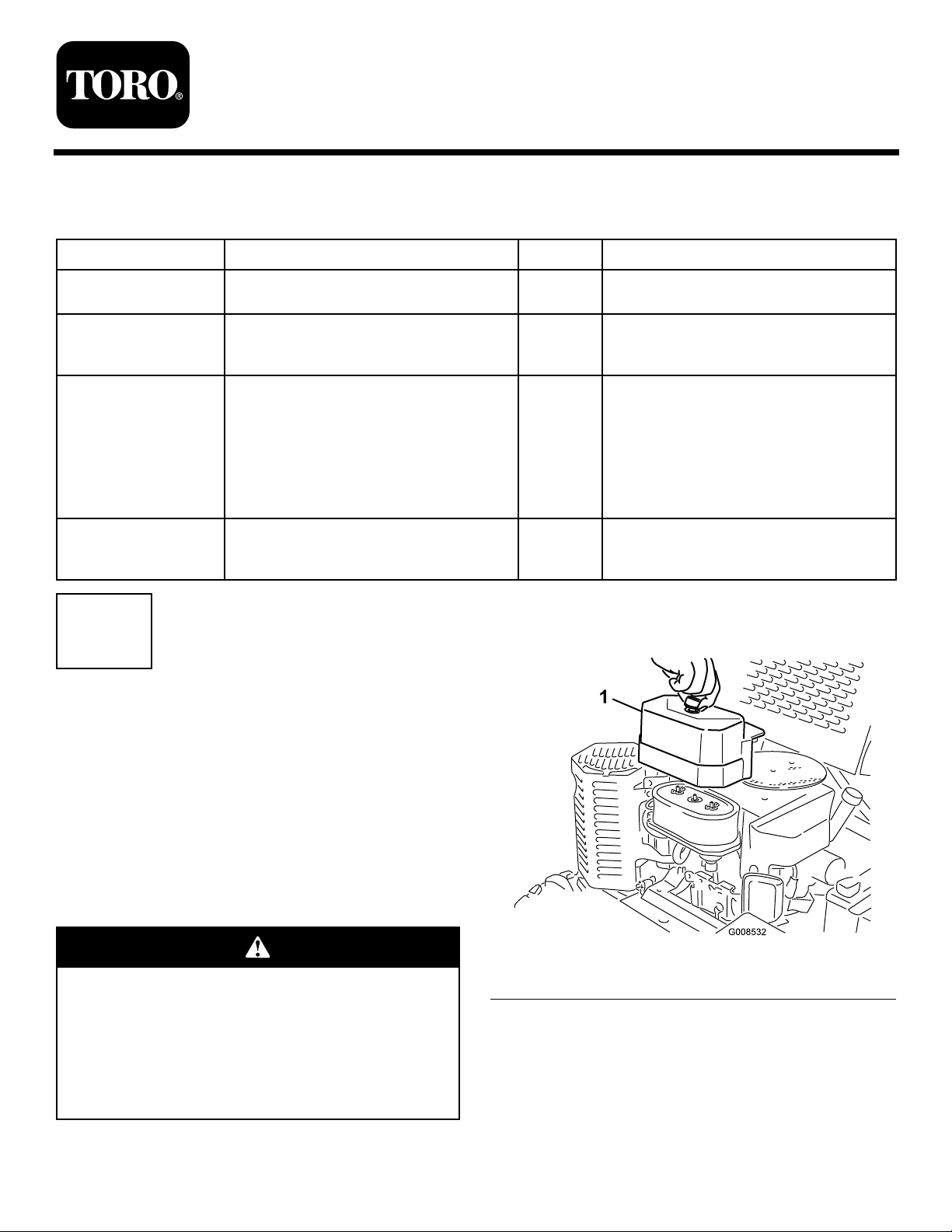
5.Removetheaircleanercover(Figure1).
Figure1
1.Aircleanercover
6.Removeanddiscardthebreathertubefromthe
engineandcarburetor(Figure2).
©2008—TheToro®Company
8111LyndaleAvenueSouth
Bloomington,MN55420
Registeratwww.Toro.com.OriginalInstructions(EN)
PrintedintheUSA.
AllRightsReserved
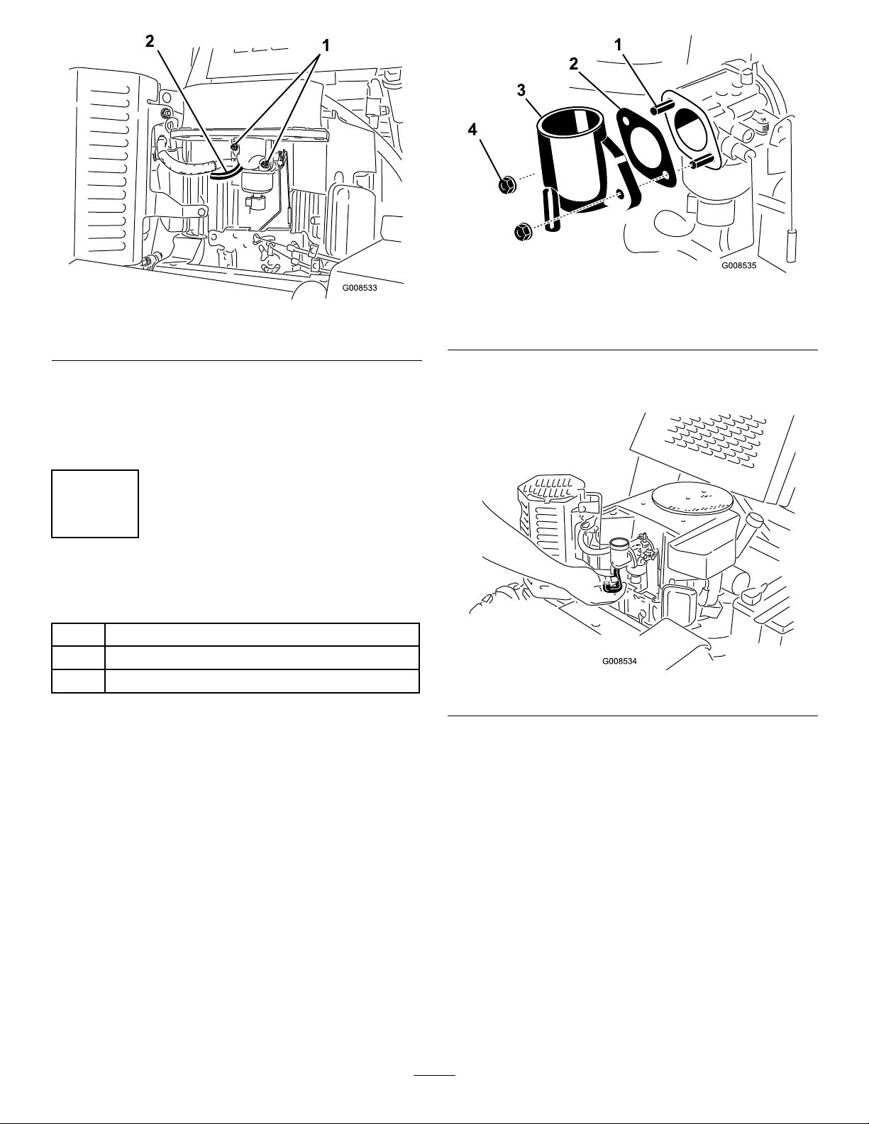
Figure2
1.Flangenuts2.Breathertube
7.Removeandsavethe2angenutssecuringtheair
cleaner(Figure2).
8.Removeanddiscardtheaircleanerandgasketfrom
thecarburetor.
2
InstallingtheIntakePipe
Partsneededforthisprocedure:
1Intakepipe
1Gasket
1Breathertube
Procedure
1.Installanewgasketandintakepipeontothe
carburetorusingtheangenutsyouremoved
previously(Figure3),andtorquetheangenutsto
52to69in-lb(6to7.5N-m).
Figure3
1.Carburetorstud3.Intakepipe
2.Gasket4.Flangenut
2.Installthenewbreathertubebetweentheintakepipe
andtheengine(Figure4).
Figure4
2

3
InstallingtheAirCleaner
Partsneededforthisprocedure:
1Enginemountingbracket
1Canisterassembly
3Flange-headbolt
2Washer
2Lockwasher
2Nut
1Plug
Procedure
1.Assembletheenginemountingbrackettothe
canistermountingbracketusing2ange-headbolts,
washers,lockwashers,andnutsasshowninFigure5.
Figure5
1.Enginemountingbracket5.Lockwasher
2.Canistermountingbracket6.Nut
3.Flange-headbolt7.Plug
4.Washer
2.Installtheplugintothediagnosticportontheair
cleanercanister(Figure5).
3.Removeandsavetheboltontheupperandinner
edgeofthemuferguardasshowninFigure6.
Figure6
1.Bolt2.Muferguard
4.Removetheboltsecuringtheuppercornerofthe
valvecoverontheleftsideofthemachine(Figure7).
Figure7
1.Mountingbracket
assembly
3.Boltremovedfromthe
valvecover
2.Boltremovedfromthe
muferguard
4.Flange-headbolt
5.Installthemountingbracketassemblytotheengine
asshowninFigure7,usingtheboltyouremoved
3

fromthemuferguard,theboltyouremovedfrom
thevalvecover,andanewange-headboltfromthe
kit.
Important:Ensurethatyouinsertthemounting
bracketbetweentheengineandthemufer
guardasshowninFigure7.
4
ConnectingtheAirCleanerto
theEngine
Partsneededforthisprocedure:
1Largeairhose
3Hoseclamp
1Weathercap
Procedure
1.Iftheairintakeportisnotpointingstraightup,
loosentheboltandnutsecuringthecanister
mountingstraps,rotatethecanistersothattheport
isup,andtightentheboltandnuttosecurethe
canister(Figure8).
Figure8
1.Canister4.Airintakeport
2.Mountingbracketstrap5.Nut
3.Bolt
2.Slidetwohoseclampsontothelargeairhose
(Figure9).
Figure9
1.Hoseclamp2.Largeairhose
3.Installtheairhoseontotheintakepipeonthe
carburetorandthelowerportonthecanister
(Figure9).
4.Slidethehoseclampsoverthehoseandlipofthe
intakepipeandlowerportandtightenthemto
securethehose.
5.Placeahoseclampovertheportonthebottomof
theweathercap(Figure10)
4

Figure10
1.Weathercap3.Airintakeport
2.Hoseclamp
6.Installtheweathercapontotheairintakeportand
tightenthehoseclamp(Figure10).
Maintenance
ReplacingtheAirFilter
ServiceInterval:Every250hours(morefrequentlyif
operatingconditionsareextremely
dustyorsandy).
Note:Servicetheaircleanermorefrequentlyif
operatingconditionsareextremelydustyorsandy.
Important:Topreventenginedamage,always
operatetheenginewiththeairlterandcover
installed.
1.Stoptheengine,removetheignitionkey,andlower
theboom.
2.Releasethelatchesontheaircleanerandpulltheair
cleanercoveroffoftheaircleanerbody(Figure11).
1
2
3
3
4
G008661
Figure11
1.Airlterbody3.Latches
2.Airlter4.Aircleanercover
3.Cleantheinsideoftheaircleanercoverwith
compressedair.
4.Gentlyslidetheairlteroutoftheaircleanerbody
(Figure11).Avoidknockingthelterintotheside
ofthebody.
Important:Neverattempttocleantheairlter.
Replaceitafter250hours
5.Carefullyslidetheprimarylterintothecanister
(Figure11).Ensurethatitisfullyseatedbypushing
ontheouterrimofthelterwhileinstallingit.
Important:Donotpressonthesoftinsidearea
ofthelter.
6.Installtheaircleanercoverwiththesidemarked
“UP”facingupandsecurethelatches(Figure11).
5

FormNo.3360-523RevA
Kitdeltrodeairedeserviciopesado
paraZanjadorasTRX
ModelNo.115-4029
InstallationInstructions
LooseParts
Usethechartbelowtoverifythatallpartshavebeenshipped.
ProcedureDescriptionQty.Use
1Nopartsrequired–Retireellimpiadordeaireexistente.
Tubodeadmisión1
Junta1
2Tubodelrespiradero1
Instaleeltubodeadmisión
Soportedemontajedelmotor1
Conjuntodelcartucho1
Pernoconarandelaprensada3
Arandela2
Arandeladefreno2
Tuerca2
3
Tapón1
Instaleellimpiadordeaire.
Mangueradeairegrande1
Abrazadera3
4Caperuza1
Conecteellimpiadordeairealmotor.
1
Cómoretirarellimpiadorde
aireexistente
NoPartsRequired
Procedure
1.Aparquelamáquinaenunasupercienivelada,pare
elmotor,retirelallavedecontactoybajelaespada.
2.Dejequeelmotorseenfríetotalmenteantesde
continuar.
Sielmotorhaestadoenmarcha,elsilenciador
yelprotectordelsilenciadorestaránmuy
calientesypuedencausarlequemaduras.Este
procedimientorequierequetoqueelprotector
delsilenciador.
Dejequeseenfríentotalmenteelmotoryel
silenciadorantesdeinstalarestekit.
3.Cierrelaválvuladecierredelcombustible.
4.Limpietodalasuciedadylosresiduosdelamáquina.
5.Retirelatapadellimpiadordeaire(Figure1).
©2008—TheToro®Company
8111LyndaleAvenueSouth
Bloomington,MN55420
Registeratwww.Toro.com.OriginalInstructions(EN)
ImpresoenEE.UU.
AllRightsReserved

Figure1
1.Tapadellimpiadordeaire
6.Retireydesecheeltubodelrespiraderodelmotory
delcarburador(Figure2).
Figure2
1.Tuercasconarandela
prensada
2.Tubodelrespiradero
7.Retireyguardelas2tuercasconarandelaprensada
quesujetanellimpiadordeaire(Figure2).
8.Retireydesecheellimpiadordeaireylajuntadel
carburador.
2
Instalacióndeltubode
admisión
Partsneededforthisprocedure:
1Tubodeadmisión
1Junta
1Tubodelrespiradero
Procedure
1.Instaleunjuntanuevayeltubodeadmisiónenel
carburadorusandolastuercasconarandelaprensada
queretiróanteriormente(Figure3),yaprietelas
tuercasconarandelaprensadaa6–7,5Nm(52–69
pulgadas-libra).
Figure3
1.Espárragodelcarburador3.Tubodeadmisión
2.Junta4.Tuercaconarandela
prensada
2.Instaleelnuevotubodelrespiraderoentreeltubode
admisiónyelmotor(Figure4).
2

Figure4
3
Cómoinstalarellimpiadorde
aire
Partsneededforthisprocedure:
1Soportedemontajedelmotor
1Conjuntodelcartucho
3Pernoconarandelaprensada
2Arandela
2Arandeladefreno
2Tuerca
1Tapón
Procedure
1.Monteelsoportedemontajedelcartuchoenel
soportedemontajedelmotorusando2pernoscon
arandelaprensada,arandelas,arandelasdefrenoy
tuercas,segúnsemuestraenFigure5.
Figure5
1.Soportedemontajedel
motor
5.Arandeladefreno
2.Soportedemontajedel
cartucho
6.Tuerca
3.Pernoconarandela
prensada
7.Tapón
4.Arandela
2.Instaleeltapónenelconectordiagnósticodel
cartuchodellimpiadordeaire(Figure5).
3.Retireyguardeelpernodelbordesuperiorinterior
delprotectordelsilenciador,segúnsemuestraen
Figure6.
Figure6
1.Perno2.Protectordelsilenciador
4.Retireelpernoquesujetalaesquinasuperiordela
tapadelaválvulaenelladoizquierdodelamáquina
(Figure7).
3
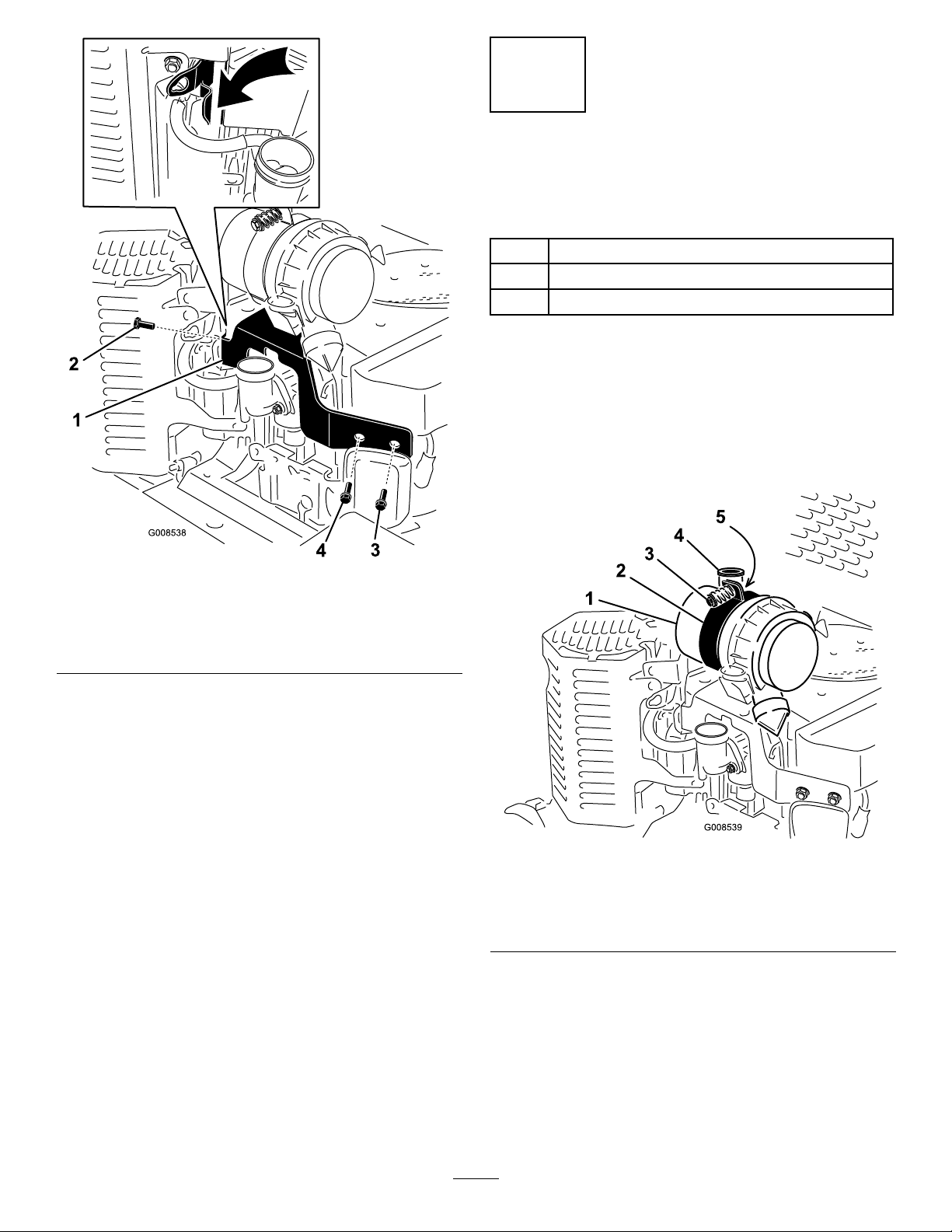
Figure7
1.Conjuntodesoportede
montaje
3.Pernoretiradodelatapa
delaválvula
2.Pernoretiradodel
protectordelsilenciador
4.Pernoconarandela
prensada
5.Instaleelconjuntodelsoportedemontajeenel
motorsegúnsemuestraenFigure7,usandoelperno
queretiródelprotectordelsilenciador,elpernoque
retiródelatapadelaválvulayunpernoconarandela
prensadanuevodelkit.
Important:Asegúresedeinsertarelsoporte
demontajeentreelmotoryelprotectordel
silenciadorsegúnsemuestraenFigure7.
4
Conexióndellimpiadordeaire
almotor
Partsneededforthisprocedure:
1Mangueradeairegrande
3Abrazadera
1Caperuza
Procedure
1.Silaentradadeairenoestáorientadadirectamente
haciaarriba,aojeelpernoylatuercaquesujetanlas
abrazaderasdemontajedelcartucho,gireelcartucho
hastaquelaentradaquedehaciaarriba,yaprieteel
pernoylatuercaparasujetarelcartucho(Figure8).
Figure8
1.Cartucho4.Entradadeaire
2.Abrazaderadelsoportede
montaje
5.Tuerca
3.Perno
2.Deslicedosabrazaderassobrelamangueradeaire
grande(Figure9).
4
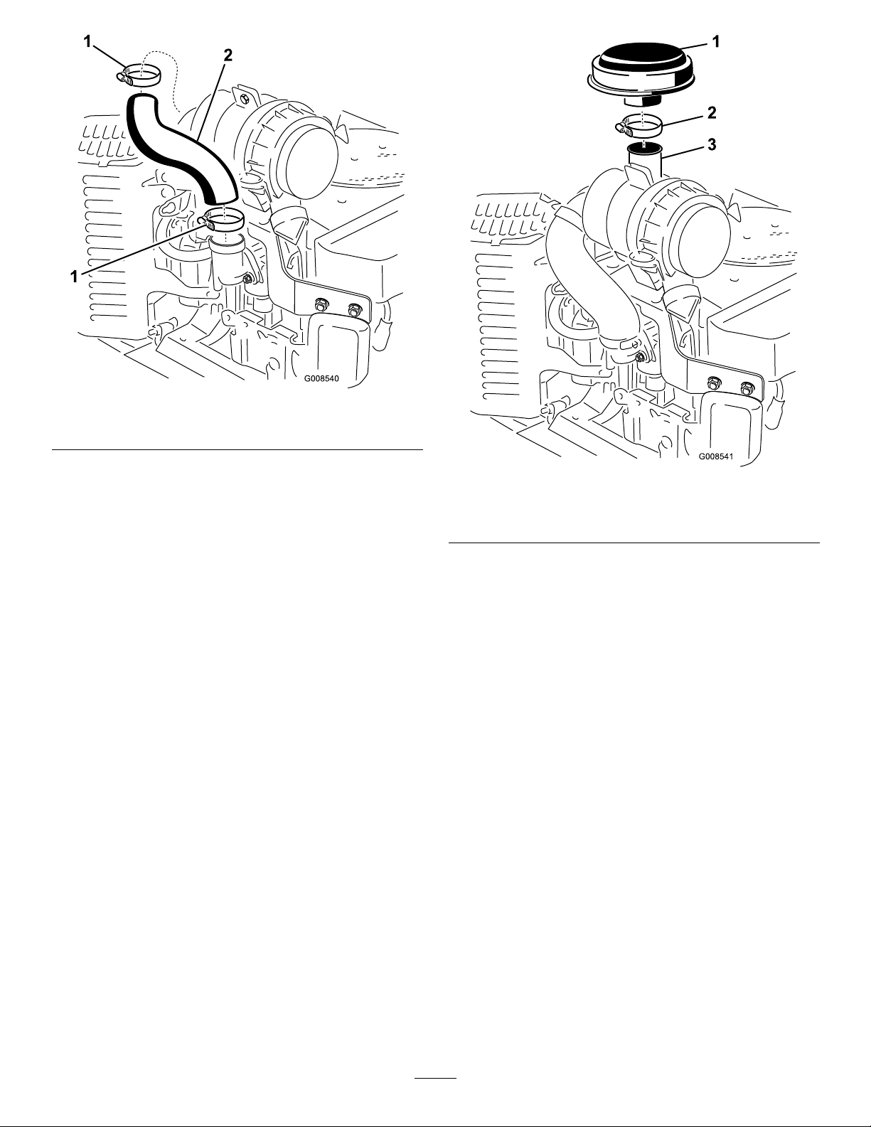
Figure9
1.Abrazadera2.Mangueradeairegrande
3.Instalelamangueradeairesobreeltubodeentrada
delcarburadoryeloricioinferiordelcartucho
(Figure9).
4.Deslicelasabrazaderassobrelamangueraysobre
elbordedeltubodeentradayeloricioinferior,y
apriételasparasujetarlamanguera.
5.Coloqueunaabrazaderasobreeloricioinferiorde
lacaperuza(Figure10).
Figure10
1.Caperuza3.Entradadeaire
2.Abrazadera
6.Instalelacaperuzasobrelaentradadeaireyapriete
laabrazadera(Figure10).
5

Maintenance
Cambiodelltrodeaire
ServiceInterval:Every250hours(Conmásfrecuencia
silazonadetrabajotienemucho
polvooarena).
Note:Reviseellimpiadordeaireconmayorfrecuencia
encondicionesdetrabajodemuchopolvooarena.
Important:Paraevitardañarelmotor,nohaga
funcionarnuncaelmotorsinqueesténinstalados
elltrodeaireylatapa.
1.Pareelmotor,retirelallavedecontactoybajela
espada.
2.Abraloscierresdellimpiadordeaireytiredelatapa
dellimpiadordeaireparasepararladelacarcasadel
limpiadordeaire(Figure11).
1
2
3
3
4
G008661
Figure11
1.Carcasadelltrodeaire3.Cierres
2.Filtrodeaire4.Tapadellimpiadordeaire
3.Limpieelinteriordelatapadellimpiadordeaire
conairecomprimido.
4.Extraigaconcuidadoelltrodeairedelacarcasadel
limpiadordeaire(Figure11).Evitegolpearelltro
contraelladodelacarcasa.
Important:Nointentenuncalimpiarelltrode
aire.Cámbielocada250horas
5.Desliceconcuidadoelltroprimariosobreel
cartucho(Figure11).Asegúresedequeestábien
asentadoempujandosobreelbordeexteriordelltro
mientrasloinstala.
Important:Noempujesobrelazonablanda
interiordelltro.
6.Instalelatapadellimpiadordeaireconelladoque
llevalapalabra"UP"haciaarriba,yjeloscierres
(Figure11).
6
Table of contents
Languages:
Other Toro Water Filtration System manuals

Popular Water Filtration System manuals by other brands

Aerus
Aerus HF 500 Operation manual

Watts
Watts LYNC UV-H Installation, operation & maintenance manual

AquaCo
AquaCo SYS-RO924TM5 Operations & installation guide

Pentair
Pentair CLEARPRO TECHNOLOGY TR100 Installation and user guide

Ideal Living
Ideal Living AQUATru AT2020 owner's manual

Eastwood
Eastwood 31633 instructions

Vivreau
Vivreau PURITY 450 Quell ST manual

Swim & Fun
Swim & Fun 1927 user manual

Sterilight
Sterilight Ozone S2ROZAP Installation instructions and owner's manual

Berkefeld
Berkefeld TWA 6 operating instructions

Aquasana
Aquasana Rhino Well 1 Water with UV owner's manual

Parker Hiross
Parker Hiross HFN 005 user manual


