Torrans double glider User manual

Double Glider Assembly Instructions.
Thank you for purchasing your new Torrans Manufacturing
Company’s Lawn Glider. Assembly of the Glider can be
accomplished by one person however, it is advised that
you have a helper during a few of the assembly steps to
lessen the chance of marring the powder coat finish.
Your chair seat and back may not resemble the pictures shown in these instructions.
Instructions are for all styles of double gliders. Picture of assembled chair may not look
like the style you have.
Working on a clean padded surface or a lawn is recommended. Avoid concrete as your
assembly area.
DO NOT OVER TIGHTEN! THIS WILL RESULT IN BREAKING THE POWDERCOAT
AND WILL VOID YOUR WARRANTY!
Occasionally, when opening your metal lawn furniture, you may encounter some
slight discoloration. This is caused by moisture in the packaging. You can com-
pare this to the stain in the kitchen sink you get after leaving something metal for
too long. This and many other scuff marks can be easily removed with Chrome
Polish and a soft cloth.
Please CAREFULLY read, understand and follow ALL the steps in these Assembly In-
structions AND Complete Each Step Before Moving On To The Next.
Care and maintenance of your new Glider is quite minimal. The finish is Exterior Grade,
Ultra Violet resistant Powder Coat and it will keep its gloss and smooth appearance for
many years of enjoyment. It is resistant to all non abrasive household cleansers and any
common kitchen product can be used. However, Powder Coat is NOT scratch proof. It
does compare in hardness to the finish of modern automobile paints. Generally a good
bath with a soapy sponge removes all common yard stains. We have found a small appli-
cation of liquid auto wax such as “NU-FINISH” lessens efforts required to remove repeat
stains such as bird droppings and tree sap and increases the gloss of the Powder Coat.
A drop or two of lubricate from time to time will remove squeaks in the nylon bushings of
the Swing Arms.
NOTE: When moving assembled Glider, grasp Main Frame and NOT Seat and Back
Chair assembly of DOUBLE Glider.
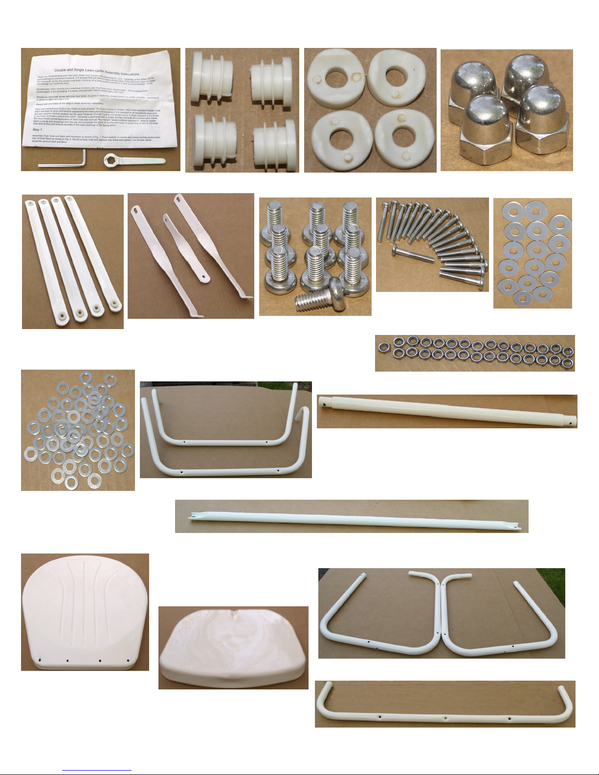
1 set of instructions with tools 4 end caps 4 plastic spacers 4 acorn nuts
4 swing arms 2 side supports-
1 center support
DG-19 long screws
DG-10 short screws 16 large washers
DG–58 small washers
DG-29 lock nuts SG-19 lock nuts
U-Shaped chair frame crossmember
2 chair frame arms
Chair Back
2 Chair Seat
2
2 main frames
Main frame back crossmember
Chair frame front crossmember
Double Glider Parts List

Step 1.
Assemble Chair Seats and Backs with hardware as shown in Fig. 1. Place WASHER on SCREW and ensure
screw enters from REAR of CHAIR BACK as shown in Fig. 2. Set ALL screws, nuts and washers into place and
tighten.
Fig. 1Fig. 2
AS VIEWED FROM CHAIR BACK
Step 2.
Place assembled Seats and Backs side by side on level surface as shown in Fig.3. Locate Center Support as
shown in Fig. 4. Using short screw with washer, secure Center Support and both Seat and Back assemblies
together as shown in Fig. 3 with washer and nut. DO NOT FULLY TIGHTEN.
Fig. 3 Fig. 4
Finish joining Seat and Back assemblies by placing short screw with washer through mounting holes ated on
underside at front of Chair Seats. Secure with washer and nut. TIGHTEN THIS SCREW ONLY. Set assembly
aside.
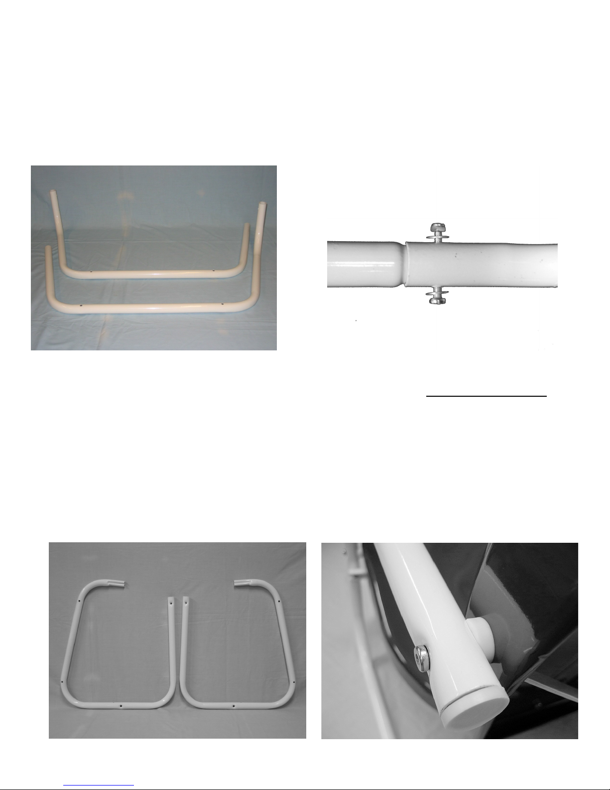
Step 3.
Locate Two Main Frame parts as shown in Fig. 5.
Insert Main Frame Back crossmember with reduced ends into Main Frames.
Align mounting holes and secure with long screws, washers and nuts as shown in Fig. 6 . TIGHTEN ALL
SCREWS. Place plastic end caps into each end of frame. Set assembly aside.
Fig. 5 Fig. 6
Step 4.
Locate both Chair Frame Arms as shown in Fig. 7. Note dimples in frame parts AT ROUND END ONLY and
ensure these dimples face away from Seat and Back as shown in Fig. 8
Locate “U” shaped chair frame crossmember. Note TOP dimple at mounting hole. Ensure TOP dimple faces
away from Chair Frame Arms as shown in Fig. 9.
Slip crimped ends of each Chair Frame Arm into “U” shaped rear crossmember. Tap down until fully seated.
Assemble Chair Frame as shown in Fig. 9.
Fig. 7 Fig. 8

Chair frame front crossmember attaches to INSIDE FRONT of Chair Frame with screws and washers and is
secured with washers and nuts as shown in Fig. 10.
DO NOT FULLY TIGHTEN. Insert plastic end caps as shown in Fig. 13.
Fig. 9 Fig. 10
Step 5.
CAREFULLY place Seat and Back assembly into Chair Frame.
Align Center Support with mounting hole on center of “U” shaped crossmember ensuring Support lands
UNDER “U” shaped crossmember as shown in Fig. 11
Place screw with washer through MIDDLE MOUNTING HOLE and Center Support and secure with washer
and nut. DO NOT FULLY TIGHTEN.
Place screws with washers through mounting hole at back of Chair Frame. Align with mounting holes of Chair
Back and place Plastic spacer between Chair Frame and Chair Back as shown in Fig. 12.
Fig. 11 Fig. 12
Locate TWO Side Supports as shown in Fig. 13. Place Side Supports over screws in Chair Back as shown in
Fig. 14. Ensure Support lands under “U” shaped Cross Member as shown in Fig. 14. Secure with nuts and
washers. DO NOT FULLY TIGHTEN. Place screws with washers through mounting holes of “U” shaped
crossmember and Side Supports and secure with washers and nuts. DO NOT FULLY TIGHTEN.
Fig. 13 Fig. 14
Move to front of assembly and place screws with washers partially through Chair Frame. Align with mounting
holes of Chair Back and place plastic spacer between Chair Frame and Chair Seat. Push screw through fully.
Secure with washers and nuts. TIGHTEN ALL SCREWS AND NUTS. Set assembly aside.
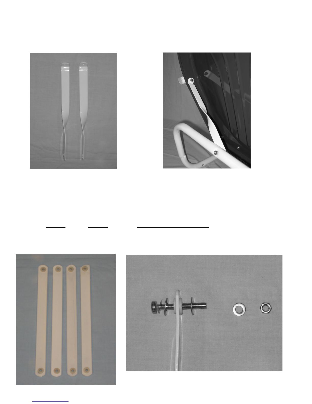
Step 6
Return To Main Frame assembly. Locate FOUR Swing Arms as shown in Fig. 15. Swing Arms are mounted
with screws, SMALL washer, LARGE washer on BOTH SIDES OF BUSHING and secured with washer and nut
as shown in Fig. 16.
Fig. 15 Fig. 16
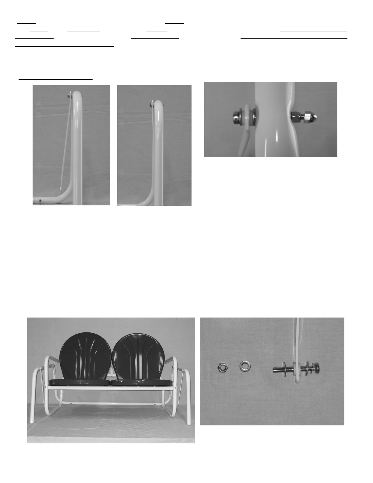
NOTE: SWING ARMS HAVE SLIGHT BEND ON EACH END. When Swing Arms are attached to Main Frame
they MUST be in CORRECT position facing AWAY from main frame as shown in Fig. 17 WHEN SCREWS ARE
TIGHTENED. Swing Arms are shown INCORRECTLY attached in Fig. 18. THREADS OF SCREWS MUST BE
ON OUTSIDE OF MAIN FRAME. Place all Swing Arms onto Main Frame and TIGHTEN NUT UNTL RESIS-
TANCE IS FELT. Swing Arms should move freely BUT have some resistance to their movement. Place protec-
tive Acorn Nut as shown in Fig. 19 and tighten.
Fig. 17 CORRECT Fig. 18 INCORRECT Fig. 19
Step 7
CAREFULLY place Seat and Back Chair assembly into Main Frame as shown in Fig. 20.
Swing Arms attach to bottom frame of Seat and Back Chair assembly. Arrange hardware as follows: screw,
small washer, large washer, Swing Arm, large washer as in Fig. 21.
Slightly raise Seat and Back Chair assembly and push remaining threads of screw through mounting hole of
Seat and Back Chair assembly. Secure with washers and nuts. Tighten until resistance is felt.
Attach all Swing Arms in same fashion.
Fig. 20 Fig. 21
This completes Glider assembly.
Table of contents
Popular Indoor Furnishing manuals by other brands

Better Homes and Gardens
Better Homes and Gardens BH16-084-499-03 manual

Teknion
Teknion Leverage installation guide

Comfort
Comfort 60-6212 Operation manual

Teknion
Teknion COMPLEMENTS NAVIGATE TABLE - ELECTRIC Installation guides

Inval
Inval MTV 22619 Assembly instructions

CHAT BOARD
CHAT BOARD Classic installation guide


John Lewis
John Lewis Morgan Guest Bedstead 800/61601 instructions

Steelcase
Steelcase 2 Series Removal and Installation Instructions

ERGOBOND
ERGOBOND Zusana instruction manual

VonHaus
VonHaus 2500359 user manual

Till-Hilft
Till-Hilft 89944.330 Assembly instructions

Pfister
Pfister Johann Jakob Valsa 29205 manual