TORREY PINES SCIENTIFIC EchoTherm IC20 User manual

OPERATING MANUAL
EchoTherm
DIGITAL, ELECTRONIC CHILLING/HEATING DRY BATH
MODELS IC20, IC20XR, IC20XT, IC30, IC30XR, & IC30XT
Applies to version 5.7 and higher
DOCUMENT NUMBER IC20-100
Revised Feb 2021
TORREY PINES SCIENTIFIC, INC.
2713 Loker Ave. West
Carlsbad, CA 92010
TELEPHONE: (760)-930-9400
TOLL FREE: (866)-573-9104
FAX: (760)-930-9480
E-Mail: info@torreypinesscientific.com
Web site: www.torreypinesscientific.com

Torrey Pines Scientific, Inc. 2
Table of Contents
I. INTRODUCTION................................................................................................4
II. WARRANTY .....................................................................................................4
III. RETURN OF ITEMS ........................................................................................4
IV. LABELS ..........................................................................................................5
V. CAUTIONS.......................................................................................................5
CHILLER/HEATER PLATE SURFACE...........................................................5
ELECTRICAL..................................................................................................5
VI. GENERAL DESCRIPTION..............................................................................6
HEATER/CHILLER PLATE.............................................................................6
TIMER.............................................................................................................6
ALARM ...........................................................................................................6
DATA LOGGER..............................................................................................6
VII. FRONT AND REAR PANEL CONTROLS......................................................7
FRONT PANEL...............................................................................................7
REAR PANEL.................................................................................................8
VIII. SET UP PARAMETERS................................................................................9
SET UP PARAMETERS.................................................................................9
SET UP INSTRUCTIONS...............................................................................9
ENVIRONMENTAL INFORMATION...............................................................9
IX. DISPLAY AND KEYBOARD DESCRIPTIONS. ............................................10
DISPLAY.......................................................................................................10
PUSH BUTTONS..........................................................................................11
X. SETTING TEMPERATURE AND OTHER FEATURES.................................12
SETTING TEMPERATURE ..........................................................................12
SETTING TIMER..........................................................................................12
SETTING THE UNIT TO “IDLE MODE”........................................................15
DATA LOGGER............................................................................................17
XI. TEMPERATURE CALIBRATION..................................................................19
Two-Point User Calibration...........................................................................19

Torrey Pines Scientific, Inc. 3
Single-Point User Calibration.......................................................................20
MENU: Calibrate...........................................................................................21
MENU: Reset Cal Points...............................................................................22
XII. TEMPERATURE MEASUREMENT ERROR CODES..................................23
XIII. RS232 SERIAL COM INTERFACE.............................................................24
Cable Pinout.................................................................................................24
COM Settings ...............................................................................................24
XIV. CLEANING, MAINTENANCE, AND CONSUMABLE PARTS....................25
CLEANING ...................................................................................................25
MAINTENANCE............................................................................................25
SPARE PARTS AND CONSUMABLES........................................................26
XV. ADDITIONAL SYMBOLS.............................................................................26
APPENDIX A: Commands Using the Serial Port.............................................27

Torrey Pines Scientific, Inc. 4
I. INTRODUCTION
Congratulations on your purchase of an EchoThermDigital Electronic Chilling/Heating Dry
Bath Series IC20/IC30. Please read the instructions carefully to insure that youreceivethe
maximum benefit from it. Also, be sure to go to our web site and register your unit for
warranty coverage.
II. WARRANTY
Torrey Pines Scientific warrants this product to be free from defects in material and
workmanship for a period of one year from the date of purchase. If repair or adjustment is
necessary and has not been the result of abuse or misuse within the one year period,
please return---freight prepaid---and correction of the defect will be made without charge.
Out of warranty products will be repaired on a charge basis.
III. RETURN OF ITEMS
Authorization must be obtained from our Customer Service Department before
returning items for any reason. When applying for authorization, please include data
regarding the reason the items are to be returned. For your protection, items must be
carefully packaged toprevent damageinshipmentandinsured againstpossibledamage
or loss. Torrey Pines Scientific will not be responsible for damage resulting from careless
or insufficient packing. A 15% restocking charge will be made on all unauthorized returns.
Note: Torrey Pines Scientific reserves the right to make improvements in design,
construction, and appearance without notice.

Torrey Pines Scientific, Inc. 5
IV. LABELS
There are various labels on the body of this unit. Listed below are the labels and their
meanings.
This symbol means: ATTENTION. The INSTRUCTION MANUAL IS TO
BE CONSULTED FOR FURTHER INFORMATION
This symbol means: WARNING. HOT SURFACE.
This symbol means: GROUND OR EARTH CONNECTIONS
V. CAUTIONS
CHILLER/HEATER PLATE SURFACE
The IC20/IC30 Series are capable of chilling and heating the plate surface from -10ºC
(-20C on XT versions) to 100ºC (110ºC on XR versions). Temperaturesfrom 44ºC(110ºF)
to 100ºC (212ºF) are hot enough to burn the skin if touched. Use extreme caution at all
times. Never leave your unit accessible to others when it is hot. Never touch the plate
surface unless you are sure it is cool. Note that there is a red LED on the front panel
marked HOT. This will illuminate when the heater surface goesabove50.0°C (122°F).
ELECTRICAL
Thecooling/heating module in the IC20/IC30 Series runsusing12voltsDCat4.2ampsfor
the IC20 and 8.4 amps for the IC20XR, IC20XT & all IC30’s. The units are supplied with a
universal power supply that can take inputs from 100 to 260 volts AC, 50/60 Hz. The units
are supplied with an AC input cord for the power supply. Be certain to use a line cord with
the same rating and of the same type as the one supplied by the manufacturer. Use the
normal care and precaution one would use with any electrical appliance.

Torrey Pines Scientific, Inc. 6
VI. GENERAL DESCRIPTION
Torrey Pines ScientificIC20units are Peltier driven for chilling &heating. Theycomewitha
universal power supply and the chilling/heating module. The units have only one moving
part, the DC fan that cools the unit. Everything else is solid state and should last years
without problem. All functions of the unit are accessible from the front panel via the
membrane switch and accompanying digital display.
HEATER/CHILLER PLATE
The surface is a very flat aluminum plate designed for good contact with any flat surfaced
item placed on it. The plate size of the IC20 is 2.875" (73 mm) x 4.375" (111 mm). It will
chill and heat quickly without a load on it. The temperature of the plate is sensed by a
platinum RTD mounted under the plate. The temperature controller in the unit compares
the plate temperature with the target temperature and instructs the Peltier module to heat
or chill the plate as required to keep them equal.
TIMER
All units have a countdown timer reading in hours, minutes, and seconds. Itcan be set toa
maximum of 99 hours 59min 59sec. The timer will be displayed at the same time as the
SET POINT and PLATE TEMP. It has a user settable AUTO-OFF as well. This works to
turn the chiller/heater target temperature off when the timer counts to zero.
ALARM
Theunits have an audible alarm that sounds for one minute when the timer countsdown to
zero. Touching the UP ARROW will turn the alarm off during this first minute. However, if
the alarm sounds for the entire minute, it will shut-off the sound automatically. When the
alarm first sounds, the timer will start to count up. This lets the user know how much time
has passed since the timer first sounded.
DATA LOGGER
The units are supplied with a built-in data logger. The data logger can be made to collect
up to 27,000 data points in intervals of 1/second, 1/minute, or one every 5 minutes. See
the instructions later for use.
NON-VOLATILE MEMORY
The units are equipped with EEPROM memory that will store user settings such as thelast
set point, MENU options, user changed calibration points, and logged data points. The
stored values will be recalled each time the unit powers up to maintain the configuration of
the previous session.

Torrey Pines Scientific, Inc. 7
VII. FRONT AND REAR PANEL CONTROLS
FRONT PANEL
The front panel of the IC20 series shown above has a tactile touch membrane keyboard
with audible feedback. The keyboard isused to set all operatingparameters. Thedisplayis
a two-line alphanumeric LCD with backlighting. When the unit is turned on the display will
light and show the Set Point and Plate Temp. Plate temperature will be displaying the
actual temperature of the plate surface. There are two LEDs on the front panel. One is a
power-on indicator and the other is the plate surface hot indicator that will illuminate when
the plate is at or above 50C.

Torrey Pines Scientific, Inc. 8
REAR PANEL
The rear panel shown has the on/off power switch at the left, the 12 volt dc power input
jack in the middle, the DB9 connector for the RS232 I/O port is on the right.

Torrey Pines Scientific, Inc. 9
VIII. SET UP PARAMETERS
SET UP PARAMETERS
1. Ambient operating room temperature range is from 5ºC to 40ºC.
2. Maximum altitude of operation should not exceed 2000 meters.
3. Maximum ambient operating relative humidity should not exceed 80% at 31ºC
decreasing linearly to 50% relative humidity at 40ºC.
SET UP INSTRUCTIONS
1. Place the unit on a level, dry surface.
2. Plug the power supply into the line cord provided and then into a properly grounded,
3-wire outlet of proper voltage.
3. Plug the power supply cable into the rear of the chilling/heating module.
4. Place the sample on the plate surface.
5. Turn the unit on by the switch on the rear of the chilling/heating module. The unit
display will light and the power LED will illuminate.
6. Set target temperature and timer, if wanted, according to the instructions that follow.
Note: Do not use this equipment in any manner not specified by the
manufacturer.
ENVIRONMENTAL INFORMATION
1. This unit is for installation category II.
2. This unit is rated pollution degree 2.

Torrey Pines Scientific, Inc. 10
IX. DISPLAY AND KEYBOARD DESCRIPTIONS.
DISPLAY
Thedisplayisatwo-row alphanumeric LCD with backlighting foreasyviewing. Itisusedto
set all the parameters of the units. The two push buttons enable the user to set a
temperature, to set a timer, and to calibrate the temperature against a local standard.
Figure 1 below describes the screens for several modes of operation.
Figure 1:Display Screens for Different Modes of Operation

Torrey Pines Scientific, Inc. 11
PUSH BUTTONS
Two push buttons are provided on the front of the unit for user input. One button is labeled
with an UP ARROW and the other with a DOWN ARROW. When the buttonsare pressed,
an audible beep will occur. The keys also have tactile feedback when they are depressed.
Using the buttons to set all of the parameters of the unit is accomplished via single and
double key presses.
Single key presses are accomplished by briefly pressing and releasing an UP ARROW or
DOWN ARROW button. If a single button is pressed and held for 2 seconds, the setting
will increase or decrease rapidly depending on the button pressed. For example, in the
default display, briefly pressing and releasing the UP ARROW will increase the set point
temperature by 1C with each press. If the UP ARROW is pressed and held down, the set
point will increase by 1C after the first press but after holding for 2sec the set point
temperature will rapidly increase until the button is released or until the maximum set point
for the unit is reached.
Adoublekeypressisaccomplished by simultaneously pressing and releasingbothUPand
DOWN ARROW buttons. For example, inthedefaultdisplay,brieflypressing andreleasing
both arrows will bring up the Menu on the LCD display. Scrolling to the various options in
the Menu is accomplished by pressing the UP and DOWN ARROW buttons. This manual
contains details on accessing and setting the various Menu options.

Torrey Pines Scientific, Inc. 12
X. SETTING TEMPERATURE AND OTHER FEATURES
Although the units can be set to -10ºC (-20 on XT’s), they can only go 30ºC (40ºC on XT’s)
below ambient. What that means is that the units may not reach -10ºC (-20ºC on XT’s) if
the ambient temperature is 25ºC. Also, the power available to heat and chill the plate and
samples on it is 50 watts for the IC20 and 100 watts for the IC20XR, IC20XR & All IC30’s.
This means that there are some larger loads that will not go as far hot or cold as wanted,
or, if they do, it will take longer than the unloaded plate will. For best results, use the
covers available as accessories. The part number for the cover for the aluminum blocks is
720-0009 for the IC20’s and 620-5509 for the IC30’s. Note that the IC20XR has twice the
power as the IC20 and will move samples blocks faster and farther away from room
temperature than the IC20.
SETTING TEMPERATURE
To set a temperature for the unit, simple press the UP or DOWN ARROW until the set
point temperature (“Set Point”) on the display shows the desired temperature. The unit
will now go to that temperature. Note that the actual plate temperature will be shown in
the display as “Plate”. You will be able to watch this number change as the unit drives
to the set point entered. If there is a problem with the temperature measurement
circuitry or if the calibration values are invalid, an error code will be displayed in the
location of the “Plate:” temperature. For example, if the low calibration measured value
is out of range, the unit will display “Plate: cal1”. See the “XII Temperature
Measurement Error Codes” section of this manual for a complete listing and the
appropriate course of action should an error occur.
SETTING TIMER
The timer is a countdown timer that reads in hours, minutes, and seconds continuously. It
can be set to 99 hours, 59 minutes and 59 seconds maximum. When the timer counts
down to zero, it will sound an audible alarm for one minute. When the alarm starts to
sound, the unit will then count up so that the user may see how long it has been since the
alarm timed out. The audible alarm can be turned off after it has sounded by depressing
the UP or DOWN ARROW.
The timer is set by accessing the Timer option in the Menu. See Figure 2 for details on
setting and starting the Timer. Figure 3 indicates how to stop the timer. When the timer is
stopped, the last timer value is “frozen” on the screen until either the Up or Down buttons
are pressed. This enables the user to capture the last value.
The Menu also includes Timer Options to control the features of the timer. The audible
alarm may be enabled or disabled when the timer reaches zero. If the “Auto-Off” feature is
disabled (“Auto-Off: no”), the unit will continue to control the plate to the set point
temperature when the timer reaches zero. If the “Auto-Off” feature is enabled (“Auto-

Torrey Pines Scientific, Inc. 13
Off:yes”), the unit will go into “Idle Mode” when the timer reaches zero. When the unit is in
Idle Mode, no power will be directed to the plate—the plate is essentially “turned off” and
will naturally return to room temperature. See the Idle Mode section of this manual for
more details.
Figure 2: Menu Map to Set and Start the Timer

Torrey Pines Scientific, Inc. 14
Figure 3: Menu Map to Stop the Running Timer
Figure 4: Menu Map to Select Timer Options

Torrey Pines Scientific, Inc. 15
SETTING THE UNIT TO “IDLE MODE”
Setting the unit to “Idle Mode” will internally turn off power to the heater/chiller assembly
and allow the sample to heat up or cool off naturally to ambient conditions. It is essentially
turning the set point off, which is why the set point on the LCD indicates “off” when the unit
is in Idle Mode. Idle mode may be set and cleared in different ways and the previous set
point value may be cleared or retained as described below. See Figure 5 and Figure 6 for
details on setting and clearing Idle Mode using the menu.
The unit will enter Idle Mode in two ways:
1. By using the Menu option (“Set Idle Mode”)
2. By setting the “Auto-Off” option to “yes” in the Timer Options menu. The IC25/35
will enter Idle mode when the countdown timer reaches 00:00:00 at the end of a
timer period or when a program has ended.
The unit will exit Idle Mode in the following ways:
1. By pressing either arrow button –the set point will be set to 20C.
2. By selecting “Clr Idle Mode” from the menu—the set point before the unit was set
to Idle Mode will be restored
Figure 5: Menu Map to Set Idle Mode Using the Menu

Torrey Pines Scientific, Inc. 16
Figure 6: Menu Map to Clear Idle Mode Using the Menu

Torrey Pines Scientific, Inc. 17
DATA LOGGER
The data logger collects values of actual plate temperature at intervals that can be set by
theuser. Thedatapoints,29,670maximum,maybecollectedeverysecond,everyminute,
or every five minutes as set by the user. When the unit is in Log mode, the character “L”
will be displayed on the LCD screen in the lower left corner. The data buffer can then be
down loaded whenever wanted via the RS232 I/O port (ref XIII. RS232 INTERFACE).
Figures 7, 8, and 9 show the steps to set the log period and how to start and stop a logging
session.
Figure 7: Menu Map to Set Log Period

Torrey Pines Scientific, Inc. 18
Figure 8: Menu Map to Start Logging Session
Figure 9: Menu Map to Stop Logging Session

Torrey Pines Scientific, Inc. 19
XI. TEMPERATURE CALIBRATION
In the factory, a NIST traceable calibration is performed on all IC20* units before they are
shipped. The units utilize a two-point calibration algorithm and are calibrated at 4C for the
low temperature calibration point, and 95C for the high temperature calibration point. The
external temperature measurements are taken at the center of the top plate surface on the
IC20 unit. If the user has not recalibrated the unit, the factory calibration offsets are
retrieved from memory each time the unit is powered up. The calibration feature in the
menu of the IC20 enables the user to re-calibrate the unit at the center of the plate as was
done in the factory, or to calibrate the unit relative to some other location of interest. When
the unit has been calibrated by the user, the new user calibration offsets will be retrieved
from memory at power up. The original factory calibration offsets can be easily restored
anytime using the menu function “Reset Cal Points”, which will also erase any user set
calibration points.
Default operation uses two-point calibration to ensure accuracy across the entire settable
range. The user may performatwo-pointcalibrationatdifferenttemperatures anddifferent
locations if desired. It also is possible for the unit to operate using single-point calibration.
Details on both are provided below. The choice is based on the requirements of the user’s
specific process. If it is important for multiple temperatures in a range to be accurate, then
two-pointcalibrationshouldbedonewiththelow and highcalibrationtemperaturesequalto
the corresponding low and high temperatures in the expected range. If operation at only a
single temperature is required, then single-point calibration may be appropriate with the
understanding that displayed and measured temperature values will only match at the
single calibration temperature and not at other temperatures. Executing the menu function
“Reset Cal Points” will erase any user set single-point calibration and return the unit to the
default two-point calibration.
It is important to note that user calibration requires the unit to be stable at the calibration
temperature for a minimum of 10 minutes and potentially much longer depending on the
particularsystem. Also,the tool used for measuringthe temperatureatthepointofinterest
must be appropriate, accurate, and repeatable. For example, when measuring the
temperature of a surface, a capable surface temperature probe must be used and the
location of the measurement must be consistent. If an immersion probe is used in a liquid,
the fluid volume and the depth and location of the probe in the fluid must be consistent.
Typically, consistent and accurate temperature measurement requires a skilled technique
by the user regardless of the method or hardware used. Variation in the measurement of
the temperature at the low or high calibration points will affect the temperature
measurement accuracy across the entire range of the unit so care must be taken both
during the calibration process and during verification of the calibration.
Two-Point User Calibration
Proper two-point calibration requires the unit to be calibrated by the user at both a low
temperature and a high temperature. After calibration, thecontrolalgorithminsidetheIC20

Torrey Pines Scientific, Inc. 20
unit will control the power to the plate utilizing temperature measurement values from a
“straight line” that passes through both of the low and high calibration points. This ensures
that the temperature values both outside and between the high and low temperature
calibration points will be proportionately adjusted to achieve an accurate temperature
reading. If the need arises for the user to calibrate the unit at a point other than the center
of the plate surface (factory location), it is important that the calibration procedure be
performed at the same point at both the low and the high temperatures to ensure accuracy
across the new calibrated temperature range. For example, if the user process requires
the unit to display and heat a block to 4C, 37C, and 75C, the surface of the block should be
measured at a specific location, and all temperature measurements related to calibration
should be at that same location. In this example the low temperature calibration should be
performed at 4C and the high temperature calibration should be performed at 75C.
Furthermore, the display must be stable for 10 minutes or more before the temperature
measurements are made and entered into the unit.
Single-Point User Calibration
If the unit is expected to be operated at a single temperature point only, and calibration
at only that point is important, then single-point calibration may be considered. For
single-point calibration, the unit must be calibrated at either the low or high temperature
calibration point—but not both. The rule of thumb is if the single-point calibration point
is less than 50C, calibrate using the low temperature calibration point and if greater than
50C, then calibrate using the high temperature calibration point. For example, if the unit
is to be single-point calibrated at 37C, the low temperature calibration point should be
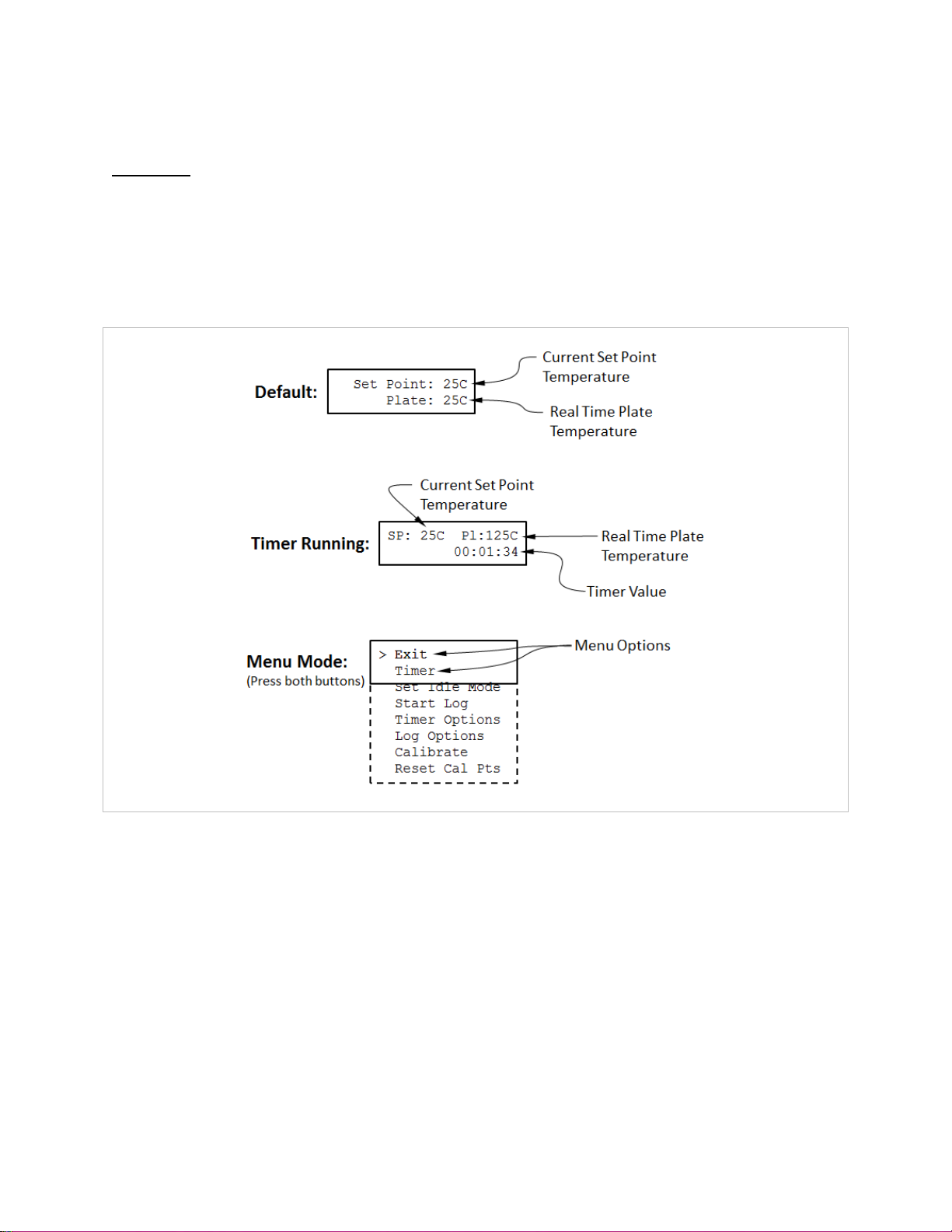
selected (37C is less than 50C). First reset the calibration points to factory values (see
Figure 11). Then calibrate the unit at 37C and store the value in the low temperature
calibration point. The display must be stable for 10 minutes or more before the
temperature measurement is made and entered into the unit.
Be aware that temperature values are adjusted based on a “straight line” between the
low and high temperature calibration points as described above. For single-point
calibration, either the low or high calibration point has been calibrated to the process,
but the other calibration point has not. This means that when single-point calibration is
utilized, the display will only match the measurement at the calibration temperature. In
other words, the displayed temperature on the unit will not match the measured
temperature for any temperature other than the single-point calibration temperature. In
the previous single-point calibration example where the low temperature calibration
point was calibrated at 37C, the measured value when the unit reads 37C will be 37C,
but when the unit reads 25C the measured value will likely be higher or lower than 25C.
*”IC20” in the above text applies to models IC20 and IC30, STD, XT, and XR
This manual suits for next models
5
Table of contents
Other TORREY PINES SCIENTIFIC Laboratory Equipment manuals

TORREY PINES SCIENTIFIC
TORREY PINES SCIENTIFIC EchoTherm RT10 User manual

TORREY PINES SCIENTIFIC
TORREY PINES SCIENTIFIC EchoTherm IC25 User manual

TORREY PINES SCIENTIFIC
TORREY PINES SCIENTIFIC EchoTherm IC22 User manual

TORREY PINES SCIENTIFIC
TORREY PINES SCIENTIFIC EchoTherm SC25 User manual

TORREY PINES SCIENTIFIC
TORREY PINES SCIENTIFIC EchoTherm SC20 User manual

TORREY PINES SCIENTIFIC
TORREY PINES SCIENTIFIC EchoTHerm RIC40 User manual