manuals.online logo
Brands
  1. Home
  2. •
  3. Brands
  4. •
  5. Toshiba
  6. •
  7. Air Conditioner
  8. •
  9. Toshiba RBM-BT14UL User manual

Toshiba RBM-BT14UL User manual

INSTALLATION MANUAL
SUPER MODULAR MULTI SYSTEM AIR CONDITIONER
T-shape branching joints (For R410A)
Model name: RBM-BT14UL, RBM-BT24UL
EH98605001-2
Please read and follow the "PRECAUTIONS FOR SAFETY" in the installation manual for the air conditioner.
• Make sure all the parts listed in the table are included in the package.
• Read the installation manual for the air conditioner regarding the selection of the size and material of the refrigerant pipes.
• Ask an authorized dealer or qualified installation professional to install this product.
• Installation work must be carried out by following this installation manual and using exclusive tools and pipes for the refrigerant R410A.
1English
Thank you for purchasing the “Branching
Joint” for TOSHIBA Carrier Air
Conditioner. Before starting the
installation work, please read this manual
carefully and install the product properly.
Parts Table
NOTE
1 ( ): indicates outer diameter.
2 For the sockets, the side with a notch is the one to connect a pipe. ( , , : without notch)
Unit: inch
[Unit: mm]
Gas side joint Liquid side joint Balance pipe joint
RBM-
BT14UL
–
Socket
No. Specifications No. Specifications No. Specifications No. Specifications
Ø1 3/8"×(Ø1 1/4")
[Ø 34.9×(Ø31.8)] 1 pc (Ø1 1/8")ר7/8"
[(Ø 28.6)ר22.2]
2 pcs
Ø5/8"×(Ø3/4")
[Ø 15.9×(Ø19.1)]
1 pc (Ø3/4")ר1/2"
[(Ø19.1)ר12.7]
2 pcs
Ø1 1/8"×(Ø1 1/4")
[Ø 28.6×(Ø31.8)] 1 pc
Joint Joint 1 pc
L-pipe (Ø1")ר1 1/8"
[(Ø 25.4)ר28.6] 1 pc T-joint 3-Ø3/4"
[3-Ø19.1] 1 pc
Heat
insulator Heat insulator for joint 1 pc Heat insulator for L-pipe 1 pc Locally procured
RBM-
BT24UL
Socket
No. Specifications No. Specifications No. Specifications No. Specifications
–
Ø1 5/8"×(Ø1 1/2")
[Ø41.3×(Ø38.1)] 1 pc
(Ø1 1/2")ר1 5/8"
[(Ø38.1)ר41.3] 1 pc Ø3/4"×(Ø7/8")
[Ø19.1×(Ø22.2)]
1 pc (Ø7/8")ר3/4"
[(Ø22.2)ר19.1]
1 pc
Ø1 3/8"×(Ø1 1/2")
[Ø34.9×(Ø38.1)] 1 pc (Ø1 1/2")ר1 3/8"
[(Ø38.1)ר34.9] 1 pc (Ø7/8")ר5/8"
[(Ø22.2)ר15.9]
2 pcs
(Ø1 1/2")ר1 1/8"
[(Ø38.1)ר28.6] 1 pc (Ø7/8")ר1/2"
[(Ø22.2)ר12.7]
1 pc
(Ø1 1/2")ר7/8"
[(Ø38.1)ר22.2] 1 pc
(Ø1 1/8")ר7/8"
[(Ø28.6)ר22.2] 1 pc
Joint Joint 1 pc
L-pipe (Ø1 1/4")ר1 1/8"
[(Ø31.8)ר28.6] 1 pc T-joint 3-Ø7/8"
[3-Ø22.2] 1 pc
T-joint 3-Ø3/8"
[
3-Ø9.5] 1 pc
Heat
insulator Heat insulator for joint 1 pc Heat insulator for L-pipe 1 pc Locally procured Locally procured
59
61 62
Diameter of the
connecting pipe
External
diameter of
socket
Socket Notch
Ø1 1/8"
Ø7/8"
L-pipe
(Ø1 1/4")
(Ø1 1/8")
Ø1 1/8"
(Ø1 1/8")
Ø7/8"
(Ø1 1/4")
Ø1 3/8" Ø1 1/4" Ø1 1/8"
(Brazed locally) (Ø1")
27
59
43
43
(Ø3/4")
Ø1/2"
Ø1/2"
Ø5/8"
(Ø3/4") 3-Ø3/4"
(Ø3/4")
13
10
10
59 43 13
10
27
(Ø1 1/2")
L-pipe
Ø7/8"
(Ø1 1/8")
Ø1 1/2"
Ø1 5/8"
Ø1 1/8"
73
Ø1 3/8"
(Ø1 1/2")
Ø1 1/2"
(Brazed locally) (Ø1 1/8")
(Ø1 1/2")
Ø1 5/8" Ø1 3/8" Ø1 1/8" Ø7/8"
71
61
62
43
61
62
(Ø1 1/2") (Ø1 1/2") (Ø1 1/2")
Ø3/4"
Ø5/8"
Ø3/4" 3-Ø7/8"
(Ø7/8")
18
14
Ø1/2"
(Ø7/8")
(Ø7/8") (Ø7/8")(Ø7/8")
18
85
14
Ø5/8"
3-Ø3/8"
62 62 18
18
61 61
14
71
85
73
43
Installation and connection
Select the model and the number of outdoor unit connection piping kits that you need based on the sales catalog, design engineering, and the
data book and installation manual of outdoor unit.
CAUTION
• When brazing the refrigerant pipes, be sure to put the nitrogen first to prevent from oxidizing the inner pipe. If not, the oxidization scale
brings the refrigerant cycle clogging and result in malfunction.
• Use clean new pipes for the refrigerant pipes, and do not let water, moisture or dust get into the pipes during installation.
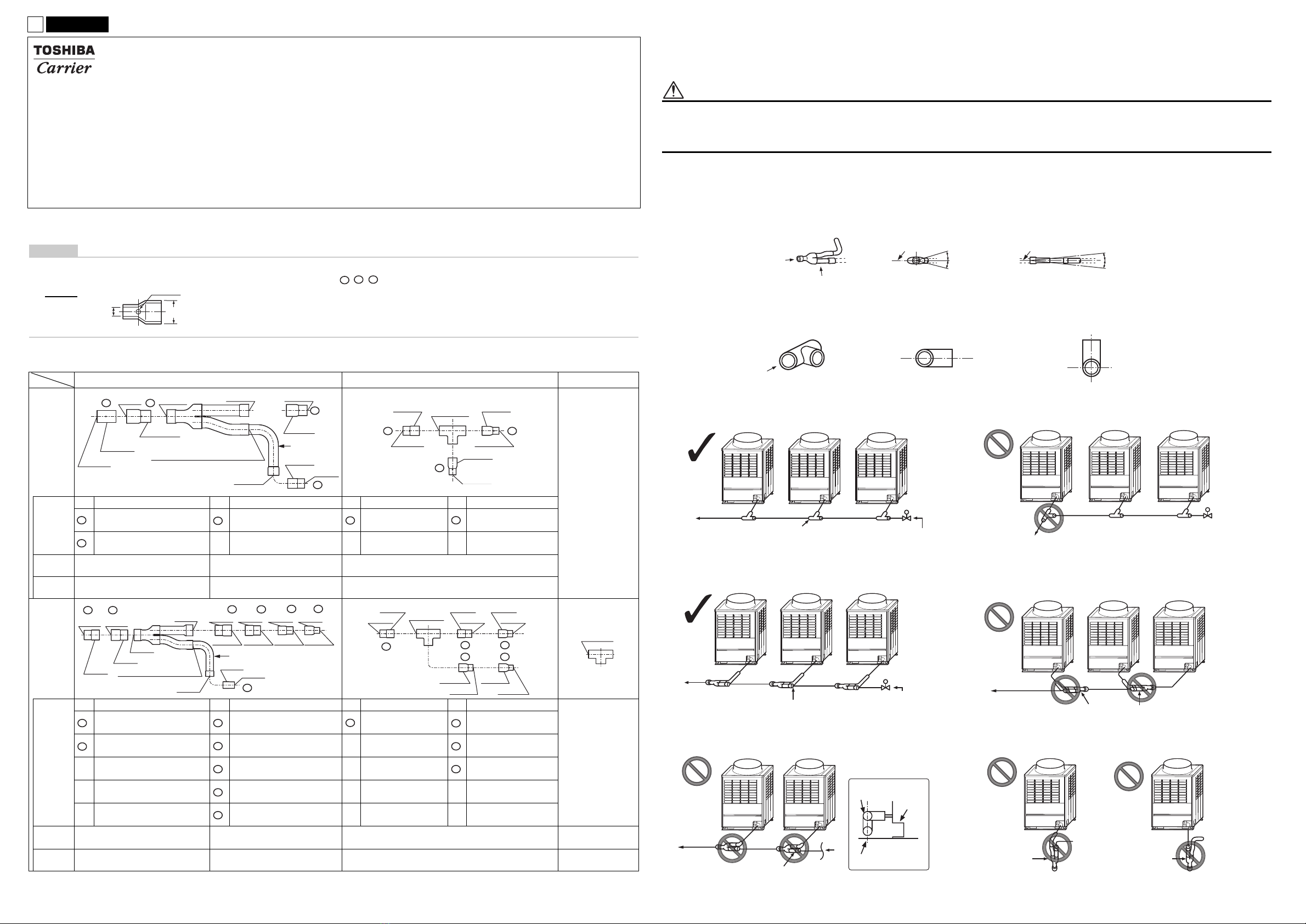
1Installation mode
<Gas joint>
Install them horizontally with a maximum gradient of ±15° for even distribution. (Do not install them perpendicularly or upright.)
(Figure 4, Figure 5, Figure 6, Figure 7)
<Liquid/balance pipe joint>
No restrictions on the installation orientation by the direction of refrigerant flow. However, on the liquid joint the installation cannot have the
refrigerant from the main pipe flow directly into the header unit. (Figure 2).
▼Liquid pipes
Figure 1 Figure 2
▼Gas pipes
Figure 3 <Gas joint reverse orientation installation>
Figure 4
<Gas joint upright orientation installation>
Figure 5
<Vertical installation>
Figure 6
<Vertical installation>
Figure 7
A
B
Horizontal line
Within ±15°
A view
Horizontal line
B view
Within ±15°
A
Horizontal line
Horizontal line
A view
A view
Header unit A Follower unit B Follower unit C
Main pipe
To indoor unit Liquid joint Extension valve installation site
(For planned system expansion)
Correct
Header unit A Follower unit B Follower unit C
To indoor unit
Main pipe
Incorrect
Header unit A Follower unit B Follower unit C
Main pipe
Gas joint
To indoor unit Extension valve installation site
(For planned system expansion)
Correct
Header unit A Follower unit B Follower unit C
Main pipe
Gas joint
To indoor unit
Incorrect
Gas joint
Header unit A Follower unit B
Main pipe
Gas joint
To indoor unit
A view
Gas joint
A
Incorrect
Unit
Vartical line
Header unit A
Gas joint
Incorrect
Header unit A
Gas joint
Incorrect
1English
2Connection Method
<Gas joint>
Determine the installation orientation of the L-pipe according to the piping connections from the outdoor unit, and select a socket that matches
the diameter of the locally procured pipes.
<Liquid joint>
Select a socket to match the diameter of the locally procured piping and install it.
<Balance pipe joint>
For 2 outdoor units system, connect directly between the header unit and the follower unit.
3Example of pipe connections
Install and connect the piping between the outdoor units as shown in the diagram below.
NOTE
There are no specific requirements on the length of the straight pipe before the joint for either the gas or liquid sides.
<For connections to the front>
To outdoor unit
Locally procured piping
To main pipe or to
other joint Inlet
Outlet (2)
Outlet (1)
Socket (Provided)
Socket (Provided)
L-pipe (Provided)
Locally procured piping
To outdoor unit or to
other joint
Gas joint (Provided)
Socket (Provided) Brazed locally
NOTE
• Select the socket (No.in ) fitting to the pipe diameter
connected to the outdoor unit.
• After cutting the pipe, be sure to remove the burrs and
polish the end surface. When some squash or
deformation, etc. occurs, improve the pipe insertion
condition by using the flare tool.
• Confirm whether no dust, water, foreign matters, etc
exists on the gas joint, the liquid joint, the balance pipe
joint and the socket to be inserted.
Locally procured piping
Socket (Provided)
To main pipe or to
liquid joint Socket (Provided)
Liquid joint (Provided)
To outdoor unit
To outdoor unit or
to other joint
Locally procured piping
Socket (Provided)
Locally procured piping
Balance pipe joint (provided)
Locally procured piping
To outdoor unit or
to other joint
To outdoor unit
or to other joint
Locally procured piping
To outdoor unit Locally procured piping
A
Outdoor unit
connection piping kit
L-pipe
Balance pipe
Gas pipe Locally procured
piping
Header unit A
Liquid pipe
Follower unit B Follower unit C
To indoor units
Balance
pipe joint
Liquid joint
Gas joint
A view
Horizontal line
Gas joint
<For connections to the bottom>
Remove the knock-out hole from the bottom of the outdoor units.
(Refer to the installation manual of the outdoor unit.)
4Heat insulating for pipes
• Insulate the joints of the liquid pipe, gas pipe, and balance pipe individually.
• Insulator for the liquid joint and the balance pipe joint are not provided. Please procure it locally.
<Gas pipe>
• Use heat insulators with heat resistance of 248 °F or more for the gas pipe.
• In order to prevent dripping condensation, do not leave any gap between heat insulator for branching joint (included in package) and heat
insulator for pipe (locally procured). And then, wrap the seam with heat insulator with thickness of 0.4" or more (locally procured).
How to apply the insulation to the gas joint
<Liquid /balance pipe>
• To heat insulate the T-joints, use a commercially available joint cover (for T-shape) that is with 0.4" or more thickness, or one applied with
machining as shown in the figure.
• Seal the T-joints completely without any gap to prevent condensation and dripping water.
A
Locally procured
piping
Gas joint
Balance
pipe
L-pipe
20" or more
Header unit A
Liquid pipe
Follower unit B Follower unit C
To indoor units
Gas pipe
Liquid joint
Balance
pipe
joint
A view
Horizontal line
Gas
joint
Heat insulator
(Locally procured)
Heat insulator
(Provided)
Joint
No gap
Taping (Locally procured)
Heat insulator
(Locally procured)
Heat insulator
(Provided)
Locally procured
piping heat insulator
(with thickness of 0.4"
or more)
No gap
Locally procured
piping insulator
(with thickness of
0.4" or more)
6"
Seal with vinyl tape
90° cutout
Insulated pipe 90°
Seal the seams with
urethane foam
Insulated pipe
Heat insulator
Diameter of
insulated pipe joint
Cut at 90°
4"ormore
ØD
ØD

This manual suits for next models

1

Other Toshiba Air Conditioner manuals

Toshiba RAS-16BAVG-E User manual

Toshiba

Toshiba RAS-16BAVG-E User manual

Toshiba RAS-18 Series User manual

Toshiba

Toshiba RAS-18 Series User manual

Toshiba RA S-25N4KVRG-ND User manual

Toshiba

Toshiba RA S-25N4KVRG-ND User manual

Toshiba RAV-SM304MUT-E User manual

Toshiba

Toshiba RAV-SM304MUT-E User manual

Toshiba RAS-107 User manual

Toshiba

Toshiba RAS-107 User manual

Toshiba RAS-18UKP-ES User manual

Toshiba

Toshiba RAS-18UKP-ES User manual

Toshiba MMU-AP0071MH User manual

Toshiba

Toshiba MMU-AP0071MH User manual

Toshiba RAV-SM404SDT-E User manual

Toshiba

Toshiba RAV-SM404SDT-E User manual

Toshiba RAS-18N3KCV Series User manual

Toshiba

Toshiba RAS-18N3KCV Series User manual

Toshiba RAV-SM406BT-E User manual

Toshiba

Toshiba RAV-SM406BT-E User manual

Toshiba RAS-10U2FVG-NZ User manual

Toshiba

Toshiba RAS-10U2FVG-NZ User manual

Toshiba RAS-25PKVPG-ND User manual

Toshiba

Toshiba RAS-25PKVPG-ND User manual

Toshiba RAV-SM562KRT-E User manual

Toshiba

Toshiba RAV-SM562KRT-E User manual

Toshiba RAS-M10SMUV-E User manual

Toshiba

Toshiba RAS-M10SMUV-E User manual

Toshiba MMK-AP0074MH-TR User manual

Toshiba

Toshiba MMK-AP0074MH-TR User manual

Toshiba MMD-AP0074SPH-E User manual

Toshiba

Toshiba MMD-AP0074SPH-E User manual

Toshiba MMY-MUP0721HT9P-UL User manual

Toshiba

Toshiba MMY-MUP0721HT9P-UL User manual

Toshiba RAV-SM560KRT-E User manual

Toshiba

Toshiba RAV-SM560KRT-E User manual

Toshiba RAS-10SKV Series User manual

Toshiba

Toshiba RAS-10SKV Series User manual

Toshiba RAS-M07SKV-E User manual

Toshiba

Toshiba RAS-M07SKV-E User manual

Toshiba RAS-24UKX User manual

Toshiba

Toshiba RAS-24UKX User manual

Toshiba RAV-SP1104AT8-E User manual

Toshiba

Toshiba RAV-SP1104AT8-E User manual

Toshiba RAV-HM801FT-E User manual

Toshiba

Toshiba RAV-HM801FT-E User manual

Toshiba RAS-15EK Series User manual

Toshiba

Toshiba RAS-15EK Series User manual

Popular Air Conditioner manuals by other brands

Daikin FDA125A5VEB Installer and user reference guide

Daikin

Daikin FDA125A5VEB Installer and user reference guide

Friedrich WallMaster WS10 Installation and operation manual

Friedrich

Friedrich WallMaster WS10 Installation and operation manual

MegaLife NEBULA GREEN R32 Use and Installation Instructions

MegaLife

MegaLife NEBULA GREEN R32 Use and Installation Instructions

TemperZone OSA 840RKTB installation guide

TemperZone

TemperZone OSA 840RKTB installation guide

Arbonia SABIANA OCEAN Series Installation and maintenance manual

Arbonia

Arbonia SABIANA OCEAN Series Installation and maintenance manual

GREE ELECTRIC GWH09TA-S3DNA1C Service manual

GREE ELECTRIC

GREE ELECTRIC GWH09TA-S3DNA1C Service manual

Samsung AC024JXADCH installation manual

Samsung

Samsung AC024JXADCH installation manual

Carrier ROOM AIR CONDITIONER operating manual

Carrier

Carrier ROOM AIR CONDITIONER operating manual

Haier 1U71S2SS5FA installation manual

Haier

Haier 1U71S2SS5FA installation manual

Klarstein Waterfall manual

Klarstein

Klarstein Waterfall manual

GE AEL05 installation instructions

GE

GE AEL05 installation instructions

ElectrIQ SF12000 user manual

ElectrIQ

ElectrIQ SF12000 user manual

Danby DPA120UB1WDB Owner's use and care guide

Danby

Danby DPA120UB1WDB Owner's use and care guide

Mitsubishi Electric BRANCH BOX PAC-MKA52BC installation manual

Mitsubishi Electric

Mitsubishi Electric BRANCH BOX PAC-MKA52BC installation manual

AAON RQ SERIES Installation operation & maintenance

AAON

AAON RQ SERIES Installation operation & maintenance

Danby dac10007ee use and care manual

Danby

Danby dac10007ee use and care manual

Mitsubishi Electric PUHZ-P200YHA installation manual

Mitsubishi Electric

Mitsubishi Electric PUHZ-P200YHA installation manual

Fujitsu AOU30RLXEH Design & technical manual

Fujitsu

Fujitsu AOU30RLXEH Design & technical manual

manuals.online logo
manuals.online logoBrands
  • About & Mission
  • Contact us
  • Privacy Policy
  • Terms and Conditions

Copyright 2025 Manuals.Online. All Rights Reserved.