Toshiba TOSVERT VF-FS1 Series Parts list manual

E6581373
TOSVERT VF-FS1 series
LONWORKS®option unit
Communication Function Manual
NOTICE
1. Make sure that this instruction manual is delivered to the end user of
LONWORKS option unit.
2. Read this manual before installing or operating the LONWORKS option unit.
Keep it in a safe place for reference.
3. All information contained in this manual are subject to change without notice.
Please confirm the latest information on our web site “www.inverter.co.jp”.

E6581373
- 1 -
Introduction
Thank you for purchasing the “LONWORKS option unit” for TOSVERT VF-FS1 series inverter.
Before using LONWORKS option unit, carefully read this function manual in order to completely and correctly
utilize its excellent performance.
After reading this function manual, please keep it handy for future reference.
For details of its general handling, see an instruction manual attached with the option unit.
* Echelon®, LONWORKS®, LONMARK®, LonTalk®, Neuron®, are the registered trademarks or the
trademarks of Echelon Corporation in the USA and other countries.
*L
ONMARK and the LONMARK Logo are managed, granted, and used by LONMARK International under a
license granted by Echelon Corporation.
Handling in general
Danger
Prohibited
Do not connect or disconnect a network cable while the inverter power is on.
It may lead to electric shocks or fire.
Mandatory
See the instruction manual attached with the option unit for cautions the handling.
Otherwise, it may lead to electric shocks, fire, injuries or damage to product.
Network control
Danger
Prohibited
Do not send the value out of the valid range to network variables.
Otherwise, the motor may suddenly start/stop and that may result in injuries.
Mandatory
Use an additional safety device with your system to prevent a serious accident due to the
network malfunctions.
Usage without an additional safety device may cause an accident.
Warning
Mandatory
Set up “Communication error trip function (see below)” to stop the inverter when the option
unit is deactivated by an unusual event such as tripping, an operating error, power outage,
failure, etc.
- Receive heart beat timer
See the “nciRcvHrtBt (Receive Heartbeat Time)” for details.
Deactivated option unit may cause an accident, if the “Communication error trip function” is
not properly set up.
Make sure that the operation signals are STOP before clearing the inverter fault. The motor
may suddenly start and that may result in injuries.
Notes on operation
Notes
When the control power is shut off by the instantaneous power failure, communication will
be unavailable for a while.
The Life of EEPROM is approximately 10000 times. Avoid writing data more than 10000
times to the same parameter of the inverter and configuration properties on LONWORKS
option unit.

E6581373
- 2 -
Table of Contents
1. Scope ..................................................................................................................................................4
1.1. Overview ....................................................................................................................................4
1.2. Applicable model ........................................................................................................................4
1.3. System configuration..................................................................................................................4
2. Names and functions of main parts.....................................................................................................5
2.1. Outline view................................................................................................................................5
2.1.1. LIU006Z.............................................................................................................................5
2.1.2. LIU007Z (for VF-FS1)........................................................................................................5
2.2. Diagnostics.................................................................................................................................6
2.2.1. Service LED.......................................................................................................................6
2.2.2. Status LED ........................................................................................................................7
2.2.3. Fault LED...........................................................................................................................7
2.3. RS485 communication port........................................................................................................8
3. Configurations .....................................................................................................................................9
3.1. Neuron ID ...................................................................................................................................9
3.2. Service pin..................................................................................................................................9
3.3. Device interface (XIF) file...........................................................................................................9
3.4. LNS Plug-in ................................................................................................................................9
3.5. Inverter configurations................................................................................................................9
3.6. Command & Setpoint selection (Local/Remote) ......................................................................10
3.7. Reference parameter of the inverter ........................................................................................11
4. Functional profile ...............................................................................................................................12
4.1. Functional profile supported by this option...............................................................................12
4.2. Object id ...................................................................................................................................12
5. Node Object functional block.............................................................................................................13
5.1. Object map...............................................................................................................................13
5.2. Network variables (Node Object) .............................................................................................13
5.2.1. nciLocation (Location Label)............................................................................................14
5.2.2. nviRequest (Object Request) ..........................................................................................14
5.2.3. nvoStatus (Object Status)................................................................................................15
6. ACMotorDrive functional block ..........................................................................................................16
6.1. Object map...............................................................................................................................16
6.2. Network variable list (VSD_6010_11) ......................................................................................17
6.3. Network variable list (the other)................................................................................................18
6.4. Configuration properties ...........................................................................................................19
6.4.1. nciMaxSpeed(Maximum Speed) ...................................................................................19
6.4.2. nciMinSpeed(Minimum Speed)......................................................................................19
6.4.3. nciRcvHrtBt (Receive Heartbeat Time) ...........................................................................20
6.4.4. nciSndHrtBt(Send Heartbeat Time)...............................................................................20
6.4.5. nciMinOutTm(Minimum Send Time)..............................................................................20
6.4.6. nciNmlSpeed(Nominal Motor Speed in min-1) ...............................................................21
6.4.7. nciNmlFreq(Nominal Motor Frequency) ........................................................................21
6.4.8. nciRampUpTm(Ramp Up Time)....................................................................................21
6.4.9. nciRampDownTm(Ramp Down Time)...........................................................................22
6.4.10. nciDrvSpeedScale(Default value for nviDrvSpeedScale) ..............................................22
6.4.11. nciPwUpOutTm (Power up delay time). ..........................................................................22
6.5. Input network variables ............................................................................................................23
6.5.1. nviDrvSpeedStpt(Drive Speed Setpoint)........................................................................23
6.5.2. nviDrvSpeedScale(Drive Speed Setpoint Scaling) ........................................................23
6.5.3. nviResetFault(Fault Reset Command) ..........................................................................23
6.5.4. nviInvSetFreq(Frequency Setpoint) ...............................................................................24
6.5.5. nviRelay1 /nviDigitalOut1,2 (Control of Digital Output)....................................................24
6.5.6. nviDigitalOutput (Control of All Digital Outputs)...............................................................24
6.5.7. nviAnalogOut1,2 (Control of Analog output) ....................................................................25
E6581373
- 3 -
6.5.8. nviEmergOverride(Emergency stop) .............................................................................25
6.5.9. nviParamCmd (Parameter access) .................................................................................26
6.6. Output network variables..........................................................................................................27
6.6.1. Output network variable update.......................................................................................27
6.6.2. nvoDrvCurnt(Drive Output Current) ...............................................................................27
6.6.3. nvoDrvSpeed(Drive Speed Feedback) ..........................................................................27
6.6.4. nvoDrvRunHours (Drive Total Running Hours) ...............................................................27
6.6.5. nvoInvOutFreq (Frequency Feedback)............................................................................27
6.6.6. nvoDrvFeedback (Velocity Feedback).............................................................................28
6.6.7. nvoStatusWord (Inverter Status) .....................................................................................28
6.6.8. nvoDrvAlarm (Alarm) .......................................................................................................28
6.6.9. nvoAlarmWord (Alarm Status) ........................................................................................29
6.6.10. nvoDrvThermal (Drive Thermal State) ............................................................................29
6.6.11. nvoMotorThermal (Motor Thermal State) ........................................................................29
6.6.12. nvoTorque (Motor Torque Monitor) .................................................................................29
6.6.13. nvoDrvEnergy (Cumulative Input Energy) .......................................................................30
6.6.14. nvoDigitalInput (All Digital Inputs Monitor).......................................................................30
6.6.15. nvoDigitalIn1 to 8 (Digital Input Monitor)..........................................................................30
6.6.16. nvoAnalogIn1 to 3 (Analog Input Monitor) .......................................................................31
6.6.17. nvoEmergStatus (Emergency Status) .............................................................................31
6.6.18. nvoParamResp (Parameter Access Response) .............................................................32
6.6.19. nvoTypeVer(Identification).............................................................................................32
7. Example usage..................................................................................................................................33
7.1. Procedure.................................................................................................................................33
7.2. Binding .....................................................................................................................................33
7.3. Option unit reset method..........................................................................................................33
7.4. Communication health management .......................................................................................34
7.5. Parameter access method .......................................................................................................35
8. Specifications ....................................................................................................................................37

E6581373
- 4 -
1. Scope
1.1. Overview
LONWORKS technology is a network control system concept developed by Echelon Corporation,
LONWORKS network provides Local Operating Network that is superior in the distributed control. it is
featured by peer to peer communication between the LONWORKS nodes. This LONWORKS option is
equipped with the LONWORKS Smart Transceiver (Neuron Chip) and LonTalk protocol in its firmware.
This network has following features.
1. Features the merit of distributed control. It enables to configure the network without Host computer.
2. The free topology wiring supported by the TP/FT-10 channel type accommodates bus, star, loop, or
several combinations of these topologies.
3. Network construction tools are commercially available, and desirable network environment can be
designed.
4. Products of the other manufacturer can also be laid out by open and non-exclusive network.
1.2. Applicable model
Applicable models are shown in the table below.
Part number of LONWORKS option unit Applicable inverter model
LIU006Z Under development
LIU007Z VF-FS1 series
1.3. System configuration
Number of connected units to the router: 63 nodes at maximum
LIU007Z
VF-FS1
Free topology: 63 units connected at maximum
Host computer
Router
LIU007Z
- The free topology wiring example.
means a node
Termination
resistor
VF-FS1
- Network configuration example
Complex topology can be configured
Router Router

E6581373
- 5 -
2. Names and functions of main parts
2.1. Outline view
The drawings below show names of main parts. Refer to each instruction manual for installing and
wiring.
2.1.1. LIU006Z
2.1.2. LIU007Z (for VF-FS1)
*1: Refer to following section.
*2: Refer to LIU007Z instruction manual (E6581371) for details.
Service LED *1
Status LED *1
Fault LED *1
LONWORKS network detachable terminal
(NETA, SHLD, NETB)
Input Selection switch *2
Service LED *1
RS485 communication port *1
Control terminals *2
Service switch *2
LONWORKS network detachable
terminal (NETA, SHIELD, NETB)
Under Development

E6581373
- 6 -
2.2. Diagnostics
2.2.1. Service LED
Service LED indicates the node condition.
1
2
3
4
5
6
1 3452
LED OFFLED ON
Power
ON
Time (second)
Continues to be OFF
Continues to be ON
Momentarily OFF then continues to be ON
Repeats ON and OFF
Repeats ON and OFF
Continues to be OFF
No Phenomenon Problem & Solutions
1Although the inverter is turned
on, LED remains OFF.
2LED continues to be ON after
the inverter is turned on.
Check the connection between the inverter and the
LONWORKS option unit. If abnormality is not found after
checking, it needs to be repaired.
3
LED is ON then OFF when
the inverter is turned on, and
it continues to be ON.
4 LED flashes every 0.5 second.
Internal application program is abnormal.
If the same indication appears after resetting the power, it
needs to be repaired.
5 LED flashes every 1 second.
This is a normal action of the "Unconfigured" device. If the
device is not "Unconfigured", Internal application program
is broken. It needs to be repaired.
6LED momentarily turns ON
then continues to be OFF.
When the program is in the condition of "Configures"
status, LED momentarily turns ON when the inverter is
turned on. Then the LED continues to be OFF for some
seconds. The node indicates "Configured" status that
means the normal condition.
-Flicker of LED
(Approximately 10Hz to 30Hz) CPU is abnormal. It needs to be repaired.
-LED turns ON while holding
down service switch. This is normal action while holding down service switch.
The phone numbers for a service call are listed on the back cover of the inverter instruction manual or
on its catalog.

E6581373
- 7 -
2.2.2. Status LED
It displays node status with green color. LIU007Z does not have this LED.
1
2
3
4
5
6
12
LED OFFLED ON
Power
ON
Time (second)
Continues to be OFF
Continues to be ON
Repeats ON and OFF
Repeats ON and OFF
Repeats ON and OFF
Repeats ON and OFF
No LED state Description
1Although the inverter is turned
on, LED remains OFF. No power
2LED continues to be ON after
the inverter is turned on. The LONWORKS option unit is running in normal mode
3 LED flashes every 1 second. There is no connection to the LONWORKS network
4 LED flashes every 0.25 second. The LONWORKS option unit has received a Wink command. It
continues for 30 second.
5Repeats 3 flashing and OFF for
1 second.
6Repeats 2 flashing and OFF for
1 second.
These phenomenon occurs when the fault LED turning ON.
CPU or Internal application program is abnormal. If the same
indication appears after resetting the power, it needs to be
repaired.
The phone numbers for a service call are listed on the back cover of the inverter instruction manual or on
its catalog.
2.2.3. Fault LED
It displays fault with red color. LIU007Z does not have this LED.
LED state Description
OFF LONWORKS option unit has no fault.
ON Hardware or software fault of the LONWORKS option unit
Flashing
The LONWORKS option unit does not communicate with the inverter.
If the same indication appears after resetting the power, it needs to be
repaired.

E6581373
- 8 -
2.3. RS485 communication port
RS485 port is useful for RS485 serial communication option (USB001Z) or Remote Keypad (RKP002Z).
Refer to the inverter instruction manual for details.
N.B.: Caution for LIU007Z
When a RS485 port of LIU007Z is used for RS485 serial communication option, the
communication option interrupts and disables the communication line between LONWORKS option
unit and the inverter. At that time LONWORKS option unit propagates the abnormality as
“Communiaction error (bit6)” in “nvoAlarmWord” and “nvoDrvAlarm” to the network. However,
“Fault (bit0)” in “nvoStatusWord” is not set at that time. this is because identify difference between
this alarm and Communication error trip (err5). This abnormality will automatically cancel itself
if the RS485 serial communication option is disconnected.

E6581373
- 9 -
3. Configurations
3.1. Neuron ID
LONWORKS device has the individual Neuron ID. The ID is indicated on the option unit as the barcode
(EAN128). Products have 3 sticker labels where the Neuron ID is indicated.
3.2. Service pin
Service pin function causes the node to propagate the service message over the network so that the
network controller finds the node. There is Service pin as a mechanical switch on the LONWORKS option
unit (refer to an attached instruction manual in detail).
3.3. Device interface (XIF) file
Device interface (XIF) files are the files that define the network-visible interface for one or more
LONWORKS devices. The device interface is the interface to a device that is exposed over a LONWORKS
network. The device interface includes the device’s self-documentation information, the number of
address table entries, the number of message tags, and the number, types, and directions of network
variables.
XIF files are distributed on our web site “www.inverter.co.jp”.
3.4. LNS Plug-in
LNS Plug-in provides one or more means to monitor or alter configuration properties or network
variables. It may be used for device-specific configuration or monitoring.
The device plug-ins are also distributed on our web site “www.inverter.co.jp”.
3.5. Inverter configurations
Set the inverter parameters according to the instruction manual attached with the product.
However, LONWORKS option unit will edit some of the inverter parameters (fh, ul, ll, acc, dec,
vl) so that they should not be edited.
Configuration by PC commissioning software (PCM001Z) is also available by using serial
communication option (USB001Z) through RS485 port.
N.B.: Refer to Section 2.3 for RS485 port specification in detail.

E6581373
- 10 -
3.6. Command & Setpoint selection (Local/Remote)
Indication to display Local/Remote mode is on the inverter unit (Refer to the inverter instruction manual
for details). LONWORKS option command and setpoint are activated on Remote mode*1. LONWORKS
option unit propagates the Local / Remote status to the network as the “Command from the network
(bit5)” and “Setpoint from the network (bit6)” in “nvoStatusWord” network variable. Inverters have some
switches to select the command and setpoint location. Following figure shows the diagram. Refer to the
inverter instruction manual for the parameter in detail.
*1: Be careful that cmod command and fmod setpoint are activated for a short time just after the
inverter power turned on. Set cmod and fmod to “Serial communication” to prevent this
problem.
Command
Setpoint
Control Terminal
Operation Panel
Serial Comm.(LONWORKS)
VIA
VIB
Operation Panel
Serial Comm. (LONWORKS)
UP/DOWN
Operation
Panel
Serial Comm.
(LONWORKS)
Operation
Panel
Local/Remote key
cmod
fmod
Logic input = 48 (SC/LC)
Network cancel switch
1
2
3
4
5
0
1
2
1
0
1
0
Rem
Loc
Rem
Loc
Serial Comm.
(LONWORKS)
LIU007Z

E6581373
- 11 -
3.7. Reference parameter of the inverter
Reference parameter of the inverter is listed below.
Title Name Description
acc Acceleration time
dec Deceleration time
fh Maximum frequency
ul Upper limit frequency
ll Lower limit frequency
vl Base frequency 1
Do not change these parameters, because
the LONWORKS option unit using them.
cmod Command mode selection
Network command has priority when the
inverter is Remote mode. (See previous
section)
fmod Setpoint mode selection
Network setpoint has priority when the
inverter is Remote mode. (See previous
section)
f111 ... Logic input terminal function Set proper value if use (See the inverter
instruction manual).
f603 Emergency stop selection For “nviEmergOverride”
f800 Communication baud rate Set “1” (default)
f801 Communication parity Set “1” (default)
f803 Communication error trip time Set properly value
f829 Communication protocol Set “1” (MODBUS)
f851 Operation at network disconnection See “section 7.4 Communication health
management”.
Warning
Mandatory
For LIU007Z, set up “Communication error trip function (f803, see the inverter
instruction manual for details)” to stop the inverter when this option unit is deactivated
by an unusual event such as tripping, an operating error, power outage, failure, etc.
Deactivated option unit may cause an accident, if the “Communication error trip
function” is not properly set up.

E6581373
- 12 -
4. Functional profile
4.1. Functional profile supported by this option
This LONWORKS option unit supports LONMARK Variable Speed Motor Drive functional profile
(SFPTvariableSpeedMotorDrive, 6010_11). It has 2 objects (functional blocks) shown in the figure
below.
Node
Object
(Mandatory)
Variable Speed
Motor Drive
Object 1
We implement the manufacturer specific variables into Variable Speed Motor Drive functional block, its
external name is “ACMotorDrive”. Node Object functional block’s external name is “NodeObject”.
4.2. Object id
Each object has individual object ID.
Object id Object name Description
0 NodeObject LONMARK functional profile: Node Object
1 ACMotorDrive LONMARK functional profile: Variable Speed Motor Drive

E6581373
- 13 -
5. Node Object functional block
The Node Object functional block includes 2 mandatory network variables “nviRequest (Object request)”
and “nvoStatus (object status)”. Upon receiving an update to the “nviRequest” network variable, the
request is processed and the “nvoStatus” network variable is updated with either the results of the
request, an in-process indication, or an error indication. The definition of the “nviRequest” network
variable includes an object ID field to allow the Node Object to report status and alarm conditions for a
device.
5.1. Object map
This figure shows the NodeObject object map.
Input Network Variable Output Network Variable
Node Object:0020_00
Mandatory
Network
Variables
Optional
Network
Variables
nvoStatus
SNVT_obj_status
nviRequest
SNVT_obj_request
Configuration Properties
nciLocation SNVT_str_asc
5.2. Network variables (Node Object)
Network variables included in Node Object functional block are shown in the table below.
LIU
007Z
LIU
006Z Name SNVT type Function LONMARK
vnviRequest SNVT_obj_request Object request Mandatory
vnvoStatus SNVT_obj_status Object Status Mandatory
--- nviTimeSet SNVT_time_stamp Time Setting Optional
--- nviFileReq SNVT_file_req File Request Optional
--- nvoFileStat SNVT_file_status File Status Optional
--- nviFilePos SNVT_file_pos File Position Optional
--- nvoFileDirectory SNVT_address File Directory Address Optional
--- nvoAlarm2 SNVT_alarm_2 Alarm output Optional
--- nviDateEvent SNVT_date_event Date Event Optional
--- nvoDateResync SNVT_switch Date Resynchronization Request Optional
--- nciNetConfig SNVT_config_src Network Configuration Source Optional
--- nciMaxStsSendT SNVT_elasped_tm Maximum Send Time Optional
vnciLocation SNVT_str_asc Location label Optional
--- nciDevMajVer unsigned short Device Major Version Optional
--- nciDevMinVer unsigned short Device Minor Version Optional
v: Support, ---:Not support.
*LIU006Z is under development.

E6581373
- 14 -
5.2.1. nciLocation (Location Label)
Configuration property, Node Object 0000_20 (Optional)
SNVT type: SNVT_str_asc (36)
SCPT reference: SCPT_location (17)
It can be used to provide physical location information.
- Valid Range:
Any NULL (“ 0”) terminated ASCII string of 31 bytes total length. In fact 30 bytes are available
because Null terminator has to be set the last byte.
- Default Value:
The default value is an ASCII string containing all Null (“ 0”).
5.2.2. nviRequest (Object Request)
Input network variable, Node Object 0000_20 (Mandatory)
SNVT type: SNVT_obj_request (92)
This is the variable to request the node status response. LONWORKS option unit supports some requests
shown in the table below.
Value Request Description
0 RQ_NORMAL If the device was in the disabled state, this request cancels that
state, and returns the functional block to normal operation.
1 RQ_DISABLED It requests the specified functional block to change to the
disabled state. This request always brings the motor to a
controlled stop.
2 RQ_UPDATE_STATUS It requests the status of the functional block to be sent to the
“nvoStatus” output network variable. The state of the functional
block is unchanged.
5 RQ_REPORT_MASK It requests a status mask reporting the status bits that are
supported by the functional block to be sent to the “nvoStatus”
output network variable. A one bit in the status mask means that
the device may set the corresponding bit in the object status
when the condition defined for that bit occurs.
7 RQ_ENABLE This request enables the system, without starting any action in
the system (no spinning of motor, etc.)
9 RQ_CLEAR_STATUS It requests all status and report bits for the functional block and in
the “nvoStatus” output network variable to be cleared. The state
of the functional block is unchanged.
10 RQ_CLEAR_ALARM It requests the alarm state of the functional block to be cleared. If
any alarm conditions are still present for the functional block, the
alarms are reported again as they are detected. If the Object
request does not change, reset will only be performed once.
N.B.: In case that receiving the invalid request, optional unit sets “1” to “invalid_request” bit of
“nvoStatus” output network variable.

E6581373
- 15 -
5.2.3. nvoStatus (Object Status)
Output network variable, Node Object 0000_20 (Mandatory)
SNVT type: SNVT_obj_status (93)
This is the variable to inform the object status. LONWORKS option unit supports some status shown in the
table below.
Bit Request Description
--- object_id object_id of requested functional block
0 invalid_id Set to “1” if a request is received for a functional block index that is not
defined in the device. No further checking of the request code is
required when set to one.
1 invalid_request Set to “1” if an unsupported request code (RQ_xxx) is received on the
“nviRequest” input network variable.
2 disabled Under the disabled state,
- Output network variables belonging to the functional block are not
propagated to the network. However, it must be possible to poll
the output network variables of a functional block in this state.
- The functional block must not respond to any updates received on
its input network variables, but it must support reading and writing
of any configuration properties belonging to the functional block.
- If the functional block was already in the disabled state, a request
to disable the functional block is not an error.
- If the Node Object functional block is disabled, any other requests
for the Node Object functional block are not disabled.
- Status and alarm reporting via the “nvoStatus” outputs is not
disabled when the Node Object functional block is disabled.
17 in_alarm Set to “1” if the inverter fault occurred or Communication fault
between the LONWORKS option unit and the inverter occurred.
19 report_mask Set to “1” if an RQ_REPORT_MASK request is received by the
“nviRequest” input network variable.

E6581373
- 16 -
6. ACMotorDrive functional block
ACMotorDrive functional block includes the “Variable Speed Motor Drive (6010_11)”. It can perform
Run/stop control of the inverter, intensive surveillance control of an operation state, monitor the inverter
status through network variables.
6.1. Object map
The object map is the following.
Input Network Variables Output Network Variables
ACMotorDrive
Mandatory
Network
Variables
Optional
Network
Variables
The other
Network
Variables
nvoDrvSpeed
SNVT_lev_percent
nviDrvSpeedStpt
SNVT_switch
nviDrvSpeedScale
SNVT_lev_percent
nvoDrvCurnt
SNVT_amp
nvoDrvRunHours
SNVT_time_hour
Configuration Properties
nciRcvHrtBt SNVT_time_sec
nciSndHrtBt SNVT_time_sec
nciMinOutTm SNVT_time_sec
nciMaxSpeed SNVT_lev_percent
nciMinSpeed SNVT_lev_percent
nciNmlSpeed SNVT_rpm
nciNmlFreq SNVT_freq_hz
nciRampUpTm SNVT_time_sec
nciRampDownTm SNVT_time_sec
nciDrvSpeedScale SNVT_lev_percent
nvoxxxxxxxxxxx
SNVT xxxxxxxx
nvixxxxxxxxxxxx
SNVT xxxxxxxx
The other Configuration Properties
ncixxxxxxxxxx SNVT_xxxxxxxx

E6581373
- 17 -
6.2. Network variable list (VSD_6010_11)
LONWORKS option unit supports all mandatory network variables included in LONMARK functional profile
“Variable Speed Motor Drive”. The network variables are shown in the table below.
“nvi” means an input network variables, “nvo” means an output network variables and “nci” means a
network configuration properties.
LIU
007Z
LIU
006Z Variables SNVT_type. unit Default value LONMARK
vnviDrvSpeedStpt SNVT_switch 0.5%,1 {0.0%, -1} Mandatory
vnvoDrvSpeed SNVT_lev_percent 0.005% Mandatory
vnviDrvSpeedScale SNVT_lev_percent 0.005% nciDrvSpeedScale Optional
vnvoDrvCurnt SNVT_amp 0.1A Optional
--- nvoDrvVolt SNVT_volt 0.1V Optional
--- nvoDrvPwr SNVT_power_kilo 0.1kW Optional
vnvoDrvRunHours SNVT_time_hour 1h Optional
--- nciLocation SNVT_str_asc Ascii Optional
vnciMaxSpeed SNVT_lev_percent 0.005% 100.000% Mandatory
vnciMinSpeed SNVT_lev_percent 0.005% 0.000% Mandatory
vnciRcvHrtBt SNVT_time_sec 0.1s 0.0s Optional
vnciSndHrtBt SNVT_time_sec 0.1s 0.0s Mandatory
vnciMinOutTm SNVT_time_sec 0.1s 0.5s Optional
vnciNmlSpeed SNVT_rpm 1min-1 1800min-1 Mandatory
vnciNmlFreq SNVT_freq_hz 0.1Hz 60Hz Mandatory
vnciRampUpTm SNVT_time_sec 0.1s 10.0s Mandatory
vnciRampDownTm SNVT_time_sec 0.1s 10.0s Mandatory
vnciDrvSpeedScale SNVT_lev_percent 0.005% 100.000% Optional
v: Support, ---: Not support.
*LIU006Z is under development.

E6581373
- 18 -
6.3. Network variable list (the other)
The other network variables are shown in the table below.
.
LIU
007Z
LIU
006Z Variables SNVT_type. unit Default value
vnviResetFault SNVT_switch 0.5%,1 {0.0%, 0}
vnviInvSetFreq SNVT_freq_hz 0.1Hz 3276.7Hz = invalid
vnvoStatusWord SNVT_state boolean
vnvoDrvFeedback SNVT_switch 0.5%,1
vnvoInvOutFreq SNVT_freq_hz 0.1Hz
vnvoDrvAlarm SNVT_switch 0.5%,1
vnvoAlarmWord SNVT_state boolean
--- nvoDrvThermal SNVT_lev_percent 0.005%
--- nvoMotorThermal SNVT_lev_percent 0.005%
vnvoTorque SNVT_lev_percent 0.005%
vnvoDrvEnergy SNVT_elec_kwh_l 0.1kWh
vnvoDigitalIn1 SNVT_switch 0.5%,1
vnvoDigitalIn2 SNVT_switch 0.5%,1
--- nvoDigitalIn3 SNVT_switch 0.5%,1
--- nvoDigitalIn4 SNVT_switch 0.5%,1
--- nvoDigitalIn5 SNVT_switch 0.5%,1
--- nvoDigitalIn6 SNVT_switch 0.5%,1
--- nvoDigitalIn7 SNVT_switch 0.5%,1
--- nvoDigitalIn8 SNVT_switch 0.5%,1
--- nvoDigitalInput SNVT_state boolean
--- nvoAnalogIn1 SNVT_lev_percent 0.005%
vnvoAnalogIn2 SNVT_lev_percent 0.005%
--- nvoAnalogIn3 SNVT_lev_percent 0.005%
vnviRelay1 SNVT_switch 0.5%,1 {0.0%, 0}
--- nviDigitalOut1 SNVT_switch 0.5%,1 {0.0%, 0}
--- nviDigitalOut2 SNVT_switch 0.5%,1 {0.0%, 0}
--- nviDigitalOutput SNVT_state boolean {0,0,...,0}
--- nviAnalogOut1 SNVT_lev_percent 0.005% 0.000%
--- nviAnalogOut2 SNVT_lev_percent 0.005% 0.000%
vnviEmergOverride SNVT_hvac_emerg binary
vnvoEmergStatus SNVT_hvac_emerg binary
vnviParamCmd SNVT_preset binary
vnvoParamResp SNVT_preset binary
vnvoTypeVer SNVT_str_asc Ascii
vnciPwUpOutTm SNVT_time_sec 0.1s 0.0s
v: Support, ---:Not support,
*LIU006Z is under development.

E6581373
- 19 -
6.4. Configuration properties
6.4.1. nciMaxSpeed(Maximum Speed)
Configuration property (nc50), Variable Speed Drive 6010_11 (Mandatory)
SNVT type: SNVT_lev_percent (81)
SCPT reference: SCPTmaxSetpoint (50)
It is used to define the maximum speed of the inverter output. The value is entered as a percent of
nominal speed. The value of the maximum speed must be validated against the value of the minimum
speed as follows:
- Valid range: 0.000 % ≤minimum speed ≤maximum speed ≤163.830 %
(Limited within the value of the inverter parameter “ul” limitation)
- Unit: 0.005%
- Default Value: 100.000%
N.B.: By editing this variable, this option unit changes the inverter parameter “ul”, automatically.
When setting small value, it may be limited by the lower limit of the inverter parameter “ul”
Danger
Prohibited
Do not set the value out of valid range.
Setting the value out of valid range may result in injuries by motor running with
unexpected speed.
6.4.2. nciMinSpeed(Minimum Speed)
Configuration property, Variable Speed Drive 6010_11 (Mandatory)
SNVT type: SNVT_lev_percent (81)
SCPT reference: SCPTminSetpoint (53)
It is used to define the minimum speed of the inverter output. The value is entered as a percent of
nominal speed. The value of the minimum speed must be validated against the value of the maximum
speed as follows:
- Valid range: 0.000 % ≤minimum speed ≤maximum speed ≤163.830 %
(Limited within the value of the inverter parameter “ll” limitation)
- Unit: 0.005%
- Default Value: 0.000%
N.B.: By editing this variable, this option unit changes the inverter parameter “ll”, automatically.
Danger
Prohibited
Do not set the value out of valid range.
Setting the value out of valid range may result in injuries by motor running with
unexpected speed.
Other manuals for TOSVERT VF-FS1 Series
5
Table of contents
Other Toshiba Power Supply manuals

Toshiba
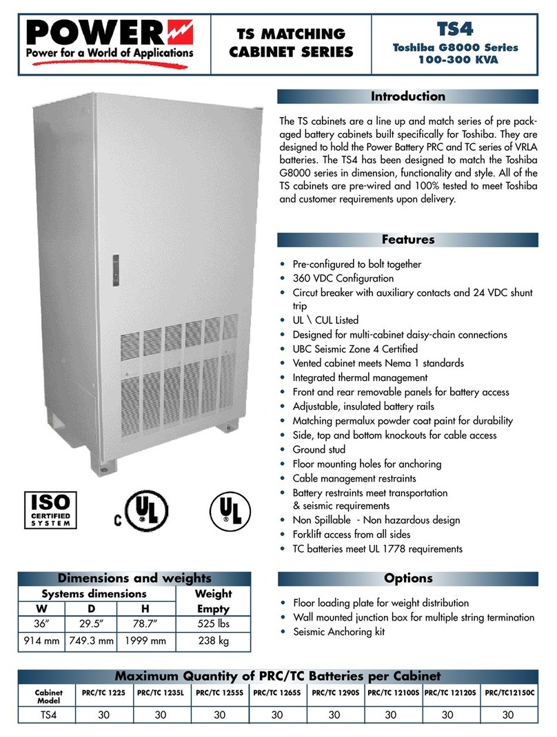
Toshiba G8000 Series User manual

Toshiba
Toshiba CPS002Z User manual

Toshiba
Toshiba TOSVERT VF-AS1 Series User manual

Toshiba
Toshiba W7 Series User manual

Toshiba
Toshiba Black Gold TB Series User manual

Toshiba
Toshiba Power TS4 User manual

Toshiba
Toshiba TOSVERT VF-PS1 User manual

Toshiba
Toshiba QX7 Series User manual

Toshiba
Toshiba 1600EP Series User manual

Toshiba
Toshiba 1600EP Series User manual