BEL LDP200-200 User manual

LDP200-200
INPUT:
200 –500 VAC, 1.4 –0.5 A (single or two phase) or 250 –725 VDC
OUTPUT:
36 –205 VDC, 2.3 A Max (187 W Max)
MAIN FEATURES
•High efficiency and compact size
•Active PFC
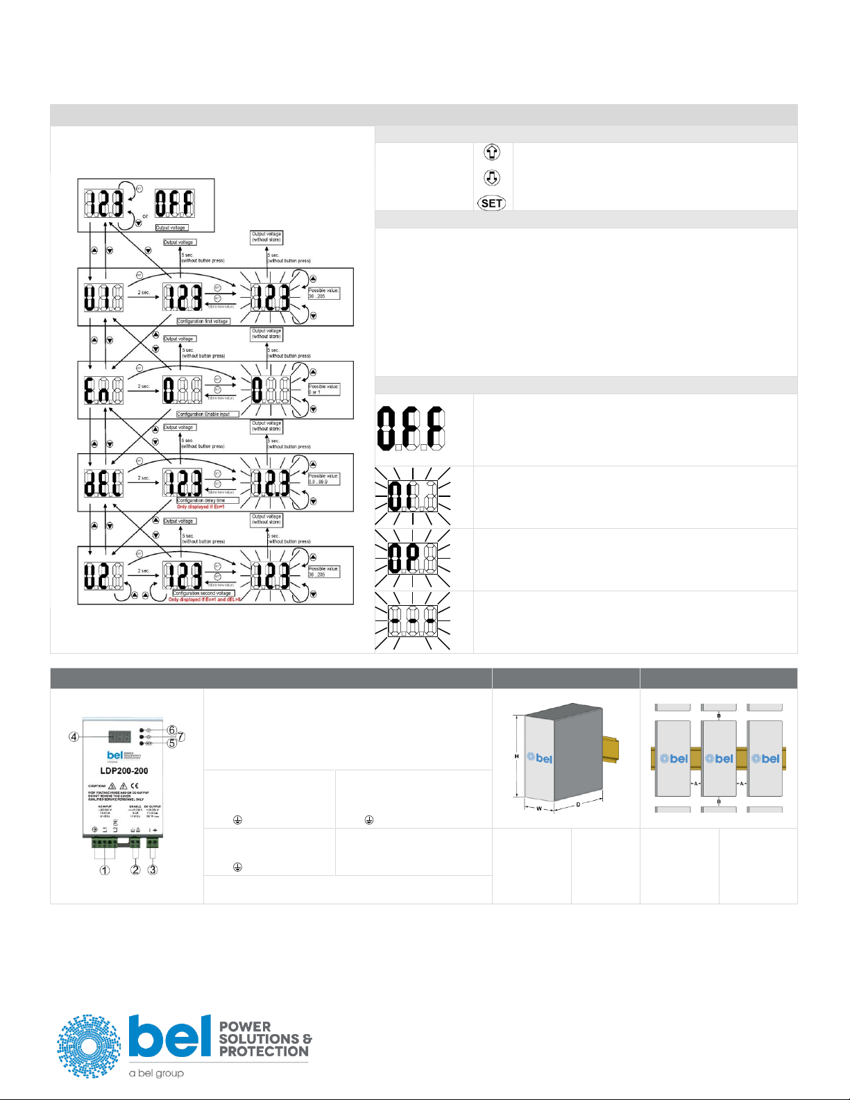
•2 user programmable voltage steps with settable duration
•Digital control
•Remote ON/OFF input
•Multiple protections
•Up to 50°C operating temperature with no derating
READ THIS CAREFULLY BEFORE
INSTALLATION!
VOR DER INSTALLATION BITTE FOLGENDE
SICHERHEITSHINWEISE BEACHTEN!
LEGGERE ATTENTAMENTE PRIMA
DELL’INSTALLAZIONE!
A LIRE ATTENTIVEMENT AVANT
L’INSTALLATION!
Before operating, read this document
thoroughly and retain it for future reference.
Non-respect of these instructions may reduce
performances and safety of the devices and
cause danger for people and property.
The products must be installed, operated,
serviced and maintained by qualified
personnel in compliance with applicable
standards and regulations.
Do not open the device, it does not contain
replaceable components, the tripping of the
internal fuse (if included) is caused by an
internal failure.
Do not repair or modify the device, if
malfunction or failure should occur during
operation, send unit to the factory for
inspection.
No responsibility is assumed by Bel for any
consequences deriving from the use of this
material.
Lesen Sie dieses Dokument vor der
Inbetriebnahme sorgfältig durch und bewahren Sie
es zum späteren Nachschlagen auf.
Die Nichtbeachtung dieser Anweisungen kann die
Funktion und Sicherheit der Geräte beeinträchtigen
und birgt Gefahren für Personen und Eigentum.
Die Geräte müssen von qualifiziertem Personal
unter Einhaltung der geltenden Normen und
Vorschriften installiert, betrieben, gewartet und
instand gehalten werden.
Öffnen Sie das Gerät nicht, es enthält keine
austauschbaren Komponenten, das Auslösen der
internen Sicherung (falls vorhanden) ist stets auf
tiefergehende Fehler im Schaltkreis zurück zu
führen.
Reparieren oder modifizieren Sie das Gerät nicht.
Sollte während des Betriebs eine Fehlfunktion oder
ein Defekt auftreten, schicken Sie das Gerät zur
Überprüfung ins Werk.
Bel übernimmt keine Haftung für die Folgen, die
sich aus dem Einsatz dieses Gerätes ergeben.
Prima dell’installazione, leggere attentamente
questo documento istruzioni e conservarle per
future consultazioni.
L’inosservanza delle presenti istruzioni può
compromettere le caratteristiche e la
sicurezza dell’apparecchio e causare pericolo
per le persone e le cose.
Il prodotto deve essere installato, utilizzato e
riparato da personale qualificato e nel rispetto
delle normative vigenti.
Non aprire il prodotto, esso non contiene
componenti sostituibili, il guasto del fusibile
interno (se previsto) è causato da un guasto
interno.
Non tentare di riparare o modificare il
prodotto, se durante il funzionamento si
verificano guasti o anomalie, inviarlo al
produttore per il controllo.
Bel non si assume nessuna responsabilità per
qualunque conseguenza derivante dall’uso di
questo materiale.
Lire ces instructions avant l'installation,
conserver ce manuel pour référence future.
Défaut de se conformer à ces instructions
peut affecter les caractéristiques et la sécurité
du dispositif, et causer du danger aux
personnes ou aux biens.
Les produits doivent être installés, exploités
et entretenus par du personnel qualifié et en
conformité avec les règlements.
N'ouvrez pas le produit, il ne contient aucune
pièce réparable, le déclenchement du fusible
interne (le cas échéant) est causé par un
défaut interne.
Ne pas essayer de réparer ou modifier le
produit ; si des défaillances se produisent
pendant le fonctionnement, retourner le
produit au fabricant pour inspection.
Bel n'assume aucune responsabilité des
conséquences éventuelles découlant de
l'utilisation des produits.
CAUTION
ACHTUNG
ATTENZIONE
AVVERTISSEMENT
RISK OF BURNS, EXPLOSION, FIRE,
ELECTRICAL SHOCK, PERSONAL INJURY.
Never carry out work on live parts! Danger of
fatal injury!
The product’s enclosure may be hot, allow
time for cooling product before touching it.
Do not allow liquids or foreign objects to enter
into the products.
To avoid sparks, do not connect or
disconnect the device before having
previously turned-off input power and wait for
internal capacitors discharge (minimum 1
minute).
GEFAHR VON VERBRENNUNGEN,
EXPLOSIONEN, FEUER, STROMSCHLAG,
PERSONENSCHÄDEN.
Führen Sie niemals Arbeiten an
spannungsführenden Teilen durch! Gefahr von
tödlichen Verletzungen! Das Gehäuse des Gerätes
kann heiß sein, lassen Sie Zeit zum Abkühlen des
Gerätes, bevor Sie es berühren.
Lassen Sie keine Flüssigkeiten oder Fremdkörper
in die Geräte eindringen.
Um Überschläge zu vermeiden, schließen Sie das
Gerät nicht an oder trennen Sie es nicht ohne
vorher die Eingangsspannung abgeschaltet zu
haben, und warten Sie die Entladung der internen
Kondensatoren ab (mindestens 1 Minute).
RISCHIO USTIONI, ESPLOSIONE,
INCENDIO, SCOSSA, LESIONI GRAVI.
Non effettuare mai operazioni sulle parti sotto
tensione! Pericolo di lesioni letali!
Il contenitore può scottare, lasciar quindi
raffreddare il dispositivo prima di toccarlo.
Non far entrare liquidi o oggetti estranei nel
dispositivo.
Per evitare scintille, non collegare o scollegare
l'apparecchiatura prima di avere tolto tensione
di ingresso e prima che sia avvenuta la
scarica dei condensatori interni (min. 1
minuto).
RISQUE DE BRULURES, EXPLOSION,
INCENDIE, ELECTROCUTION, DOMMAGE
AUX PERSONNES.
Ne jamais effectuer des opérations sur les
parties sous tension! Danger de mort!
Le boîtier peut produire des brûlures, le
laisser refroidir avant de toucher l'appareil. Ne
faire pas pénétrer des liquides ou des corps
étrangers dans l'appareil.
Pour éviter des étincelles, ne pas connecter
ou déconnecter l'équipement jusqu'à ce que
la tension d'entrée a été supprimée et avant
qu'il n'ait eut lieu la décharge des
condensateurs internes (minimum 1 minute).
INTENDED USE
BESTIMMUNGSGEMÄßER BETRIEB
USO PREVISTO
UTILISATION
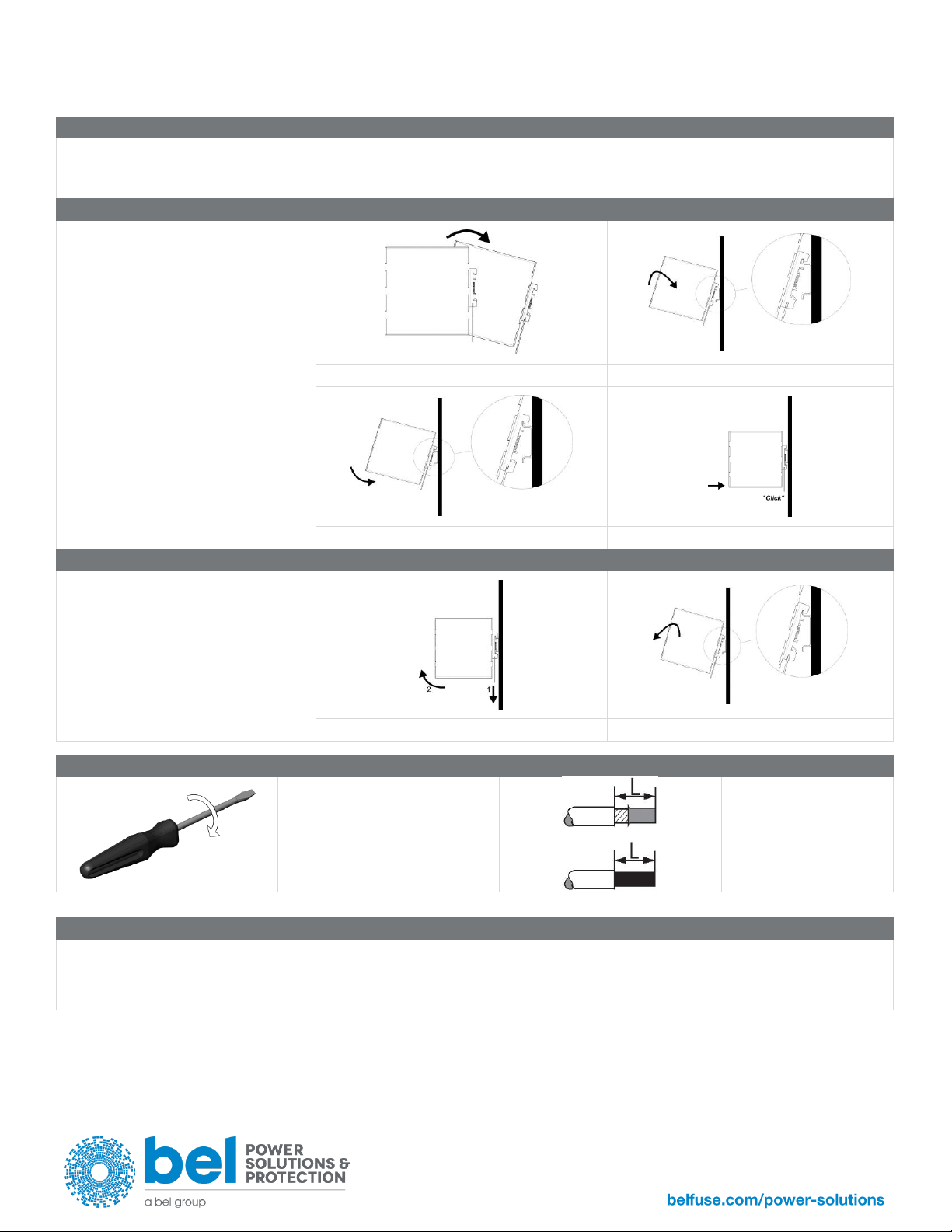
These are isolated devices suitable for SELV
and PELV circuitry and are designed to be
mounted on DIN rail and installed inside a
protective enclosure. They are intended for
general use such as in industrial control,
communication, and instrumentation
equipment.
Do not use these devices in applications
where malfunction may cause injury or death.
Es handelt sich um galvanisch getrennte Geräte,
die für SELV- und PELV-Anwendungen geeignet
sind und für die Montage auf DIN-Schienen und die
Installation in einem Schutzgehäuse konzipiert
sind. Sie sind für den allgemeinen Gebrauch wie
z.B. in industriellen Steuer-, Kommunikations- und
Automatisierung-Anwendungen vorgesehen.
Verwenden Sie diese Geräte nicht in
Anwendungen, bei denen eine Fehlfunktion zu
Verletzungen oder zum Tod führen kann.
I dispositivi sono isolati, adatti per applicazioni
SELV e PELV, sono dotati di aggancio per il
montaggio su guida DIN all’interno di quadri
elettrici o contenitori di protezione, per
l’utilizzo con controllori industriali, unità di
comunicazione o apparecchi di misura.
Non utilizzare in applicazioni in cui un
eventuale guasto può comportare rischio di
lesioni o di morte.
Les produits sont isolés, appropriés pour les
circuits TBTS et TBTP et sont équipés d'un
crochet pour montage sur rail DIN dans des
armoires ou conteneurs de protection, pour
utilisation avec les contrôleurs industriels, des
modules de communication ou des unités de
mesure.
Ne pas utiliser ces dispositifs dans une
application où un dysfonctionnement pourrait
entraîner le risque des blessures ou de mort.
ENVIRONMENTAL CHARACTERISTICS
UMGEBUNGSBEDINGUNGEN
CARATTERISTICHE AMBIENTALI
CARACTÉRISTIQUES ENVIRONMENTALES
Installation in a Pollution Degree 2
environment.
Do not use in wet area or subject to moisture.
Carefully recycle the product and related
batteries according to local regulations.
Installation in einer Umgebung mit
Verschmutzungsgrad 2.
Nicht in nassen Bereichen oder unter Feuchtigkeit
verwenden.
Das Gerät und die zugehörigen Batterien sind
entsprechend den lokalen Vorschriften zu recyceln
bzw. zu entsorgen.
Usare in ambienti con Grado di Inquinamento
2.
Non far funzionare l'apparecchio in un
ambiente umido o soggetto a formazione di
condensa. Riciclare il prodotto e le batterie
collegate, nel rispetto delle normative locali
vigenti.
Utiliser les produits dans des environnements
avec degré de pollution 2.
Ne pas employer l'appareil dans un
environnement humide ou soumis à la
condensation. Recycler les produits et les
batteries, conformément à la réglementation
locale.

LDP200-200
2
USER INSTRUCTIONS
1) DESCRIPTION
DIN rail mountable primary switched-mode power supply with 170 –528 VAC input, suitable for single or two phase mains line.
2) INSTALLATION
Use DIN-rails according to EN60715. Installation should be made vertically (see Fig.4). For better device stability fix the rail to the wall close to the point where the device
is to be mounted. In order to guarantee sufficient convection, we recommend observing a minimum distance to other modules
(see Fig.3).
Be sure to check that the mounting DIN rail is properly connected to earth (PE) before mounting the device
WARNING: Do not insert/ remove any wire if the device is not fixed to the DIN rail.
The device is provided with a thermal protection; a limited air flow can cause the thermal protection tripping.
The SMPS automatically restarts after cooling. To get normal operation reduce the temperature of the air surrounding the power supply, increase the ventilation or reduce
the load (see Fig.8)
3) CONNECTIONS
The device is equipped with pluggable screw terminals. To avoid sparks, do not connect or disconnect the connectors before having previously turned-off input power
and waited for internal capacitors discharge (minimum 1 minute)
In order to comply with UL certification, use appropriate copper cables of indicated cross section, designed for an operating temperatures of:
60°C for ambient up to 45°C
75°C for ambient up to 60°C
90°C for ambient up to 70°C
Strip the connecting ends of the wires according to the indication and ensure that all strands of a stranded wire enter the terminal connection (see Fig.5)
4) INPUT PROTECTION
The device input is provided with varistors against overvoltage. The input is not provided with internal fuses, thus an external short circuit/overcurrent protection must be
provided by the end user (see Fig.6).
For operation on a single phase or two phase system, a protection fuse on each phase must be provided.
Surge protection: it is strongly recommended to provide external surge arresters (SPD) according to local regulations.
5) AC INPUT CONNECTION
The device can be connected to single phase AC line with Vin 230 VAC and two phase line with Vin 200 –500 VAC (see Fig.7). Please connect the PE first.
6) DC INPUT CONNECTION
Connect L1 terminal to (+) positive pole, N terminal to (-) negative pole and terminal to GND. Rated voltage 250 –725 VDC.
The device is also suitable for photovoltaic or wind turbine applications (see Fig.7).
7) ENABLE INPUT CONNECTION
The device can be connected to AC lines or DC lines to provide an enable signal. With DC lines please be sure to respect the polarity.
Rated voltage 12 –230 VAC / VDC.
The ENABLE line should be provided with a fuse type T, rated 250 V / 100 mA.
The ENABLE signal allows the output voltage to be switched ON or OFF. The ENABLE signal operating modes can be configured in the configuration menu. When the
ENABLE function is not active the output is continuously ON. The ENABLE signal can also be used to change (normally a reduction) the output voltage after a defined time
(used for an “over excitation” of a brake solenoid). In the configuration menu a delay time and a second voltage must be configured to use this function.
8) OUTPUT CONNECTION
The device is suitable for SELV and PELV circuitry (having Vout higher than 60 VDC is not a SELV source).
Vout can be adjusted through a dedicated menu through the push buttons "SET" “”, “” (see Fig.8).
The voltage present at the unit output is shown on the display.
Check Vout before connecting the power supply to the load! With output voltage > 80 VDC, the continuous current must not exceed the nominal power (187 W).
9) OUTPUT PROTECTION
The device is protected against overload (OL) / short circuit / Input Undervoltage (---) / overtemperature (OT).
Protection codes are shown on the display when the protection condition is triggered.
•(OL) Overload protection: if the output power (Vout*Iout) is greater that the nominal output power (187 W) for more than 3sec the output is
witched off and “OL” is shown on the display.
•(OT) Overtemperature protection: turns off the device if the internal temperature exceeds a safe limit (see Fig.8).
•(---) Undervoltage protection: turns off the device if the input voltage is < 160 VAC. It automatically reset when the input voltage comes back
to nominal values. This code (“---“) on the display can also indicate an internal failure.
•(OL & OT) protections: No auto-recovery, recovery by primary shutdown or retrigger of enable input.
Behaviour in overload conditions: The output current is limited to 2.4 A and the output power is limited to 187 W (constant current / power limitation). If the OL persists
for > 3 s, the unit is turned OFF and the OL alarm is displayed.
Enable: Remote ON/OFF input.
Enable = 0: Every time an error is displayed the device turns OFF the output. To reset the error you should turn OFF the device and after 10 s turn it ON.
Enable = 1: Every time an error is displayed the device turns OFF the output. To reset the error you should apply a voltage (12 - 230 VAC / VDC) between the Enable
connector. If after both procedures the same error is displayed check the unit and/or the external conditions.

3
INSTALLATION INSTRUCTION
Asia-Pacific
+86 755 298 85888
Europe, Middle East
+353 61 225 977
North America
+1 408 785 5200
© 2020 Bel Power Solutions & Protection
BCM.00439_AC
CONFIGURATION MENU AND DISPLAY MODE
•Set-up push button
To move inside the
Set-up menus use
the: UP, Down and
SET button.
•
UP: Scroll up menus and values
DOWN: Scroll down menus and values
SET: Confirms selection Stored new value
•Settable Parameters
•U1: Configuration first output voltage Settable 36 –205 VDC
•
•En: Configuration Enable input
En = 0: Input Enable is disable, the output voltage it is the one set in Step U1
En = 1: Input Enable is enabled, in order to active the unit must provide an AC/DC
voltage on the Enable connector see Point 6 on Instructions. In this case you can
set the Delay (DEL) and Second output voltage (U2).
•As default setting are DEL=0.0sec and U2=U1
•
•dEL: Configuration Delay Time Settable 0.0 - 99.9 s
•
•U2: Configuration second output voltage Settable 36 - 205 VDC
•Errors Displayed
•
•
•
“OFF”:
Output inactive
“En” Enable is active (En=1) and the enable input is not active
•
“OL”:
Output switched off because the Output voltage below 30 VDC ≥3 s
No auto-recovery, recovery by primary shutdown or retrigger of
enable input.
•
“OP”:
Output switched off because of over temperature
No auto-recovery, recovery by primary shutdown or retrigger of
enable input.
•
“- - -”:
Output (power supply) switched off because of a general failure or input
voltage is < 160 VAC.
FIG.1 - CONNECTIONS
FIG.2 - DIMENSIONS
FIG.3 - DISTANCES
(1) AC input
(2) Enable input
(3) DC output (load)
(4) Display
(5) SET button menu
(6) UP button menu
(7) DOWN button menu
Input AC Line:
Single Phase
▪L1 = Line
▪N = Neutral
▪= earth ground
2 Phases
▪L1 = Phase 1
▪L2 = Phase 2
▪= earth ground
Input DC Line:
▪L1 = + Positive DC
▪N = - Negative DC
▪= earth ground
Enable:
▪E+ = Line / Positive DC
▪E - = Neutral / Negative DC
Dimension
W
D
H
mm
80
120
112
Distance
A
B
mm
20
50
Output:
+ = Positive DC / - = Negative DC

LDP200-200
4
FIG.4 - MOUNTING / DISMOUNTING INSTRUCTIONS
For DIN rail fastening according to IEC 60715 TH35-7.5(-15)
Mounting as shown in figure, with input terminals on lower side, with suitable cooling and maintaining a proper distance between adjacent devices as specified in the
Installation Instruction of each family.
MOUNTING:
1. Tilt the unit slightly backwards.
2. Fit the unit over the top edge of the rail.
3. Slide it downward until it hits the stop.
4. Press against the bottom for locking.
1
2
3
4
DISMOUNTING:
1. Pull down the slide clamp lever
2. Tilt the unit upward
3. Unhook the unit from the rail
1 & 2
3
FIG.5 - RECOMMENDED CONNECTING CABLE
Recommended Tightening torque
0.5 - 0.6 Nm
4.42 - 5.30 lbf in
Solid: 2.5 mm² / 12 AWG
Stranded:1.5 mm² / 12 AWG
L: 6.0 - 7.5 mm / 0.24 - 0.30 in
FIG.6 - INPUT PROTECTION
Fuse MCB 6 A C curve or 4 A D curve.
For USA and Canada, use the fuse type closest to the European equivalent type.
Surge protection: it is strongly recommended to provide external surge arresters (SPD) according to local regulations.

5
INSTALLATION INSTRUCTION
Asia-Pacific
+86 755 298 85888
Europe, Middle East
+353 61 225 977
North America
+1 408 785 5200
© 2020 Bel Power Solutions & Protection
BCM.00439_AC
FIG.7 - INPUT CONNECTIONS
AC LINE –SINGLE PHASE
AC LINE –TWO PHASES
DC LINE
FIG.8 - ENVIRONMENT
OPERATING TEMPERATURE
DERATING
- 40°C to + 70°C
5 - 95% r.H. non condensing
- 4.2 W / °C over 50°C
Do not exceed Vout x Iout = 100 W Max at 70°C
NOTES:
▪Data may change without prior notice in order to improve the product.
▪Please refer to the latest version of the Installation Instruction for each product by visiting
belfuse.com/power-solutions
ACCESSORIES
▪LDX-D20 20 A Active ORing controller
▪LDX-D50 50 A Active ORing controller
▪LDX-B20 150J Buffer Module
Table of contents
Other BEL Power Supply manuals

BEL
BEL LDB120 Series User manual

BEL
BEL LDC480 Series User manual

BEL
BEL LDW480 Series User manual

BEL
BEL LDT2400 Series User manual

BEL
BEL LDW25-24S User manual

BEL
BEL LDC240 Seriesl LDC240-12 User manual

BEL
BEL TCP3500-048G Series User manual

BEL
BEL LDN85 Series User manual

BEL
BEL LDW240 Series User manual

BEL
BEL LDC120 Series User manual

BEL
BEL LDN240 Series User manual

BEL
BEL LDT960 Series User manual

BEL
BEL LDN40-5 User manual

BEL
BEL FXC7000 Series User manual

BEL
BEL TET3000-12-069RA User manual

BEL
BEL LDN120 Series User manual

BEL
BEL LDW240-12 User manual

BEL
BEL TEC800-12-074NA User manual

BEL
BEL LDN20 Series User manual

BEL
BEL TET2200-12-086NA User manual