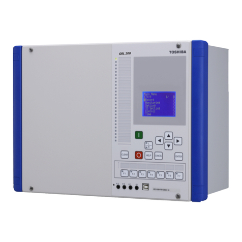
Toshiba BMS-IFWH5E User manual

ENERGY MONITORING RELAY INTERFACE
Installation Manual
Model name:
BMS-IFWH5E
Installation Manual 1
English
Manuel d’installation 11
Français
Installationshandbuch 21
Deutsch
Manuale d’installazione 31
Italiano

–1–
Energy Monitoring Relay Interface Installation Manual
Contents
1 Precautions for Safety. . . . . . . . . . . . . . . . . . . . . . . . . . . . . . . . . . . . . . . . . . . . . . . . . . 2
2 Introduction . . . . . . . . . . . . . . . . . . . . . . . . . . . . . . . . . . . . . . . . . . . . . . . . . . . . . . . . . . 3
3 Before Installation . . . . . . . . . . . . . . . . . . . . . . . . . . . . . . . . . . . . . . . . . . . . . . . . . . . . . 4
4 Installation . . . . . . . . . . . . . . . . . . . . . . . . . . . . . . . . . . . . . . . . . . . . . . . . . . . . . . . . . . . 4
5 Connection of Power cables/Earth wires/Communication cables . . . . . . . . . . . . . . 5
6 Setting. . . . . . . . . . . . . . . . . . . . . . . . . . . . . . . . . . . . . . . . . . . . . . . . . . . . . . . . . . . . . . . 8
7 Trial Operation . . . . . . . . . . . . . . . . . . . . . . . . . . . . . . . . . . . . . . . . . . . . . . . . . . . . . . . . 9
• Thank you very much for purchasing this TOSHIBA Energy Monitoring Relay Interface.
• Please read this manual carefully beforehand for proper installation of the relay interface.
1-EN

–2–
EN
Energy Monitoring Relay Interface Installation Manual
1Precautions for Safety
• Read these “Precautions for Safety” carefully before installation.
• The precautions described below include important items regarding safety. Observe them without fail.
Understand the following details (indications and symbols) before reading the body text, and follow the
instructions.
• After the installation work has been completed, perform a trial operation to check for any problems. Explain how
to use and maintain the unit to the customer.
• Ask customer to keep this Manual at accessible place for future reference.
Indication Meaning of Indication
Text set off in this manner indicates that failure to adhere to the directions in the warning could result in
serious bodily harm (*1) or loss of life if the product is handled improperly.
Text set off in this manner indicates that failure to adhere to the directions in the caution could result in
serious bodily injury (*2) or damage (*3) to property if the product is handled improperly.
*1: Serious bodily harm indicates loss of eyesight, injury, burns, electric shock, bone fracture, poisoning, and other
injuries which leave aftereffect and require hospitalization or long-term treatment as an outpatient.
*2: Bodily injury indicates injury, burns, electric shock, and other injuries which do not require hospitalization or long-
term treatment as an outpatient.
*3: Damage to property indicates damage extending to buildings, household effects, domestic livestock, and pets.
Symbols Meaning of Symbols
“ " Indicates prohibited items.
The actual contents of the prohibition are indicated by a picture or text placed inside or next to the graphic
symbol.
“ " Indicates compulsory (mandatory) items.
The actual contents of the obligation indicated by a picture or text placed inside or next to the graphic
symbol.
•Ask an authorized dealer or qualified installation professional to install or reinstall this unit.
Inappropriate installation may result in electric shock or fire.
•Electrical work must be performed by a qualified electrician in accordance with this installation
manual.
The work must satisfy all local, national and international regulations.
Inappropriate work may result in electric shock or fire.
•Be sure to turn off all main power supply switches before starting any electrical work.
Failure to do so may result in electric shock.
•Do not modify the unit.
A fire or an electric shock may occur.
•Do not install this unit where flammable gas may leak.
If gas leaks and accumulates around the unit, it may cause a fire.
•Perform wiring correctly in accordance with specified the current capacity.
Failure to do so may result in short-circuiting, overheating or fire.
•Use predefined cable and connect them certainly. Keep the connecting terminal free from
external force.
It may cause an exothermic or a fire.
WARNING
CAUTION
WARNING
CAUTION
2-EN

–3–
Energy Monitoring Relay Interface Installation Manual
2Introduction
Applications/Functions/Specifications
Applications
• The Energy Monitoring Relay Interface is used to measure and distribute the power of the air conditioner.
Functions
• The interface calculates output power pulses with connected power meters, and then sends the calculation result
to the Touch Screen Controller or other central controller.
Specifications
External View
Power supply 220V - 240VAC, 50/60Hz
Power consumption 4 W
Operating temperature/humidity 0 to 40 °C, 10 to 90% RH
Storage temperature -20 to +60 °C
Chassis material Galvanized sheet metal 0.8t
Dimensions 66(H) x 193(W) x 246(D) mm
Mass 1.35 kg
Power meter input
Input type Photo-coupler insulation
Input points 8 points
Input registance 3 k ohm
Input "ON" current 3.6 mA
Input pulse condition 50msec or more
193
77
246
246
63.6
66
77
193.4
219
234
193
12034
6-Ø5.5
mounting holes
3-EN

–4–
EN
Energy Monitoring Relay Interface Installation Manual
3Before Installation
Check the following package contents.
Use the following wiring materials to connect the signal lines and power lines. (Procured on site)
4Installation
Energy Monitoring Relay Interface Installation Method and
Orientation
There are five installation methods for this relay interface as shown below: surface mount and wall mounts.
Use the attached screws.
REQUIREMENT
Do not install the unit in any of the following places.
• Humid or wet place
• Dusty place
• Place exposed to direct sunlight
• Place where there is a TV set or radio within one meter
• Place exposed to rain (outdoors, under eaves, etc.)
Installation Space and Maintenance Space
A side space for connecting through cable inlets and an upper space for maintenance
must be reserved before installation.
The other sides can be adjacent to surrounding objects.
No. Item Quantity Remarks
1 Energy Monitoring Relay Interface 1
2 Installation Manual 1
3 Screw 4 M4 x 12mm tapping screws
4 Pin terminal 2
5Cableclamp 1
No. Line Description
1ForRS-485
Type 2-core shield wires
Wire size 1.25 mm2, 500m max. (total length)
Length
2 For connection to power meter
Type
2-core wire, 0.3mm2, 100m max.Wire size
Length
3Forpower Type H07 RN-F or 245IEC66
0.75mm2, 50 m max.
Wire size
No good
100mm
100mm
4-EN

–5–
Energy Monitoring Relay Interface Installation Manual
5Connection of Power cables/Earth wires/
Communication cables
CAUTION
• The RS-485 communication cable has polarity. Connect A to A, and B to B. If connected with incorrect polarity, the
unit will not work.
Power cables/Earth wires/Communication cables
Connect power cables, earth wires, and communication cables to the specified terminals on the terminal block.
REQUIREMENT
Disconnect the appliance from the main power supply.
This appliance must be connected to the main power supply by a circuit breaker or switch with a contact separation
of at least 3mm.
Fasten the screws to the terminal with torque of 0.5Nm.
LN
BASG
RS-485
DI1 DI6DI2 DI4
DI3 DI7 DI8DI5
1234
LED1
LED2
LED3
LED4
LED5
SW1SW2SW3
SW4SW6
SW7
+ - + - + - + - + - + - + - + -
35 35 35 6
6
10
35 10
Power supply
220-240VAC
(50/60Hz)
Length of stripped
power cable Length of stripped
communication cable
Power meter
Touch Screen Controller or other
central controller
Length of stripped
power meter wire
Insert the wire by pushing
the lever with a
screwdriver.
Check that the wire is
inserted securely.
When inserting two RS-485
communication cables into a single
terminal for connection to another
interface, crimp them using the
attached pin terminal.
Secure each cable with a
cable clamp.
Secure each
cable with a
cable clamp.
Connect the
earth wire to the
earth terminal on
the chassis.
To connect 2 cables, change the
preset cable clamp to the
provided one and fix the cables
with the cable clamp as shown in
the figure.
5-EN

–6–
EN
Energy Monitoring Relay Interface Installation Manual
Wiring Connection
The following describes a connection example of Energy Monitoring Relay Interface.
Shield earthing
• The RS-485 communication cable must be earthed on TCS-NET Relay Interface or central controller. It does not
have to be earthed on Energy Monitoring Relay Interface.
The shielded wire must be crimped with closed end connector. The shielded wire end must be insulated and left
open.
Connection of power meters
• Use a power meter with a pulse generator.
Connect the non-voltage contact output of the power meter to the Energy Monitoring Relay Interface.
An external input circuit is shown below.
Input signal is electrically isolated by photo-coupler.
(1) Example of contact input connection
(2) Example of contact input connection
CAUTION
• Output sink current has polarity.
When they are connected to inappropriate input terminal, the unit may not operate properly.
+
-
12V
Input
terminal
Contact
DI-1 to DI-8
Power meter
(with pulse generator)
Energy Monitoring Relay Interface
+
-
12V
Input
terminal
Current
sink
DI-1 to DI-8
Power meter
(with pulse generator)
Energy Monitoring Relay Interface
6-EN

–7–
Energy Monitoring Relay Interface Installation Manual
Connection diagram
AB
U1
SG
U2FG
TCC-LINK
RS-485
AB
SW5
LN
LN
SW1
SW7
SG A B
DI1
DI2
DI3
DI4
DI5
DI6
DI7
DI8
4
SW1
SW7
SG A B
DI1
DI2
DI3
DI4
DI5
DI6
DI7
DI8
1
LN
Power supply
TCS-NET RELAY
INTERFACE
Brown
Yellow
Orange
Red
Crimp 3 wires with a closed
end wire joint.
TOUCH SCREEN
CONTROLLER
Power meter 1
Power meter 2
Power meter 3
Power meter 4
Power meter 5
Power meter 6
Power meter 7
Power meter 8
Power supply
Power supply
The RS-485 communication
cable must be earthed on TCS-
NET Relay Interface or central
controller. It does not have to be
earthed on Energy Monitoring
Relay Interface.
Set the Energy
Monitoring Relay
Interface address
with SW1. Assign 1
to 8 to each address
to avoid duplication.
You can set the
Energy Monitoring
Relay Interface
address
independently from
the TCS-NET Relay
Interface address or
the Digital Input/
Output Relay
Interface address.
CAUTION: The
SW1 setting is read
when the power is
turned on. Push the
reset switch (SW6)
after changing the
address.
Set the RS-485
terminator resistor on a
TCS-NET Relay
Interface.
Set SW7 as "120 ohm"
on a Energy Monitoring
Relay Interface with
address SW1=1, when
the Energy Monitoring
Relay Interface is used
in a system without
TCS-NET Relay
Interface. Set SW7 as
"Open" on the other
interfaces.
The RS-485
communication
cable has polarity
A and B. Be careful
when connecting
the wire.
Power meter 1
Power meter 2
Power meter 3
Power meter 4
Power meter 5
Power meter 6
Power meter 7
Power meter 8
Connect the shield
wire of the two
wires
The RS-485
communication
cable has polarity A
and B. Be careful
when connecting
the wire.
TCS-NET Relay Interface
is not necessary when
using Central controller.
7-EN

–8–
EN
Energy Monitoring Relay Interface Installation Manual
6Setting
The following settings are necessary to use Energy Monitoring Relay Interfaces.
• SW1 Address set switch
When two or more Energy Monitoring Relay Interfaces are used, set a different address for each unit to
avoid address duplication.
Assign addresses in an ascending order.
CAUTION
•When the SW1 setting has been changed, push reset switch SW6. The new address setting is read.
•You can set the Energy Monitoring Relay Interface address independently from the TCS-NET Relay Interface
address or the Digital Input/Output Relay Interface address.
• SW2 Operation mode set switch These switches are not used during normal operation.
Set zero (0) or “all OFF”.
• SW3 Test switch
• SW4 Test switch
• SW6 Reset switch
When performing an address setting with SW1, push this reset switch after the address setting to read
the set value.
• SW7 RS-485 terminator resistor select switch
• Set an RS-485 terminator resistor on a TCS-NET Relay Interface, when an Energy Monitoring Relay
Interface is used with the TCS-NET Relay Interface in the same system. Set SW7 as "Open" on the
Energy Monitoring Relay Interface.
• Set SW7 as "120 ohm" on an Energy Monitoring Relay Interface with address SW1=1, when the
Energy Monitoring Relay Interface is used in a system without TCS-NET Relay Interface. Set SW7 as
"Open" on the other interfaces.
• When a Digital Input/Output Relay Interface is used with these interfaces in the same system,
terminator resistor setting on the Digital Input/Output Relay Interface is not necessary.
SW1 Address set switch
1-8 Address
0, 9-F Not used
SW2 Operating mode set switch (0 usually)
SW3 Test switch (all OFF usually)
SW4 Test switch
SW6 Reset switch
SW7
RS-485 terminator resistor select switch
120 ohm Open
LED1 Power indicator
LED2 RS-485 communication status indicator
LED3 Not used
LED4 Test indicator
LED5 Test indicator
ON ON
LN
BASG
RS-485
DI1 DI6DI2 DI4
DI3 DI7 DI8DI5
1234
LED1
LED2
LED3
LED4
LED5
SW1SW2SW3
SW4SW6
SW7
+-+-+-+-+-+-+-+-
8-EN

–9–
Energy Monitoring Relay Interface Installation Manual
7Trial Operation
Before starting trial operation
Turn on the power of the Energy Monitoring Relay Interface after all wire connections and settings are completed.
Turn on power of the air conditioning control system.
Trial operation
Confirming external input connection
• In the test mode, when the external inputs connected to the input terminals DI-1 to DI-8 are ON, the respective
LEDs will goes on so you can confirm the connection.
▼Confirming procedure:
Set the operation mode switch SW2 to “3”, and push the reset switch SW6 to enter the test mode.
Unless SW4 is pushed, the respective input status of DI-1 to DI-4 is indicated by LED2 to LED5.
When SW4 is pushed, the respective input status of DI-5 to DI-8 is indicated by LED2 to LED5.
(*) To return to the normal operation, reset SW2 to “zero (0)” and push SW6.
Checking the RS-485 communication status
Use LED2 for checking the RS-485 communication status.
When RS-485 communication with Touch Screen Controller or other central controller is normal, LED2 will blink.
LED2 LED3 LED4 LED5
SW4 OFF Displays DI-1 input status. Displays DI-2 input status. Displays DI-3 input status. Displays DI-4 input status.
SW4 ON Displays DI-5 input status. Displays DI-6 input status. Displays DI-7 input status. Displays DI-8 input status.
Input ON: LED lights
Input OFF: LED turns off
LED Normal operation Abnormal operation
LED1 Power indicator ON OFF
LED2 RS-485 communication status indicator Blinking OFF
LED3 Not used OFF —
LED4 Test indicator OFF —
LED5 Test indicator OFF —
9-EN

–10–
EN
Energy Monitoring Relay Interface Installation Manual
MEMO
..................................................................................................
..................................................................................................
..................................................................................................
..................................................................................................
..................................................................................................
..................................................................................................
..................................................................................................
..................................................................................................
..................................................................................................
..................................................................................................
..................................................................................................
..................................................................................................
..................................................................................................
..................................................................................................
..................................................................................................
..................................................................................................
..................................................................................................
..................................................................................................
..................................................................................................
..................................................................................................
..................................................................................................
..................................................................................................
..................................................................................................
..................................................................................................
..................................................................................................
..................................................................................................
..................................................................................................
..................................................................................................
..................................................................................................
..................................................................................................
..................................................................................................
10-EN

–11–
Interface relais de supervision d’énergie Manuel d’installation
`
Table des matières
1 Précautions de sécurité . . . . . . . . . . . . . . . . . . . . . . . . . . . . . . . . . . . . . . . . . . . . . . . 12
2 Introduction . . . . . . . . . . . . . . . . . . . . . . . . . . . . . . . . . . . . . . . . . . . . . . . . . . . . . . . . . 13
3 Avant l’installation. . . . . . . . . . . . . . . . . . . . . . . . . . . . . . . . . . . . . . . . . . . . . . . . . . . . 14
4 Installation . . . . . . . . . . . . . . . . . . . . . . . . . . . . . . . . . . . . . . . . . . . . . . . . . . . . . . . . . . 14
5 Connexion des câbles d’alimentation/fils de terre/câbles de communication . . . 15
6 Réglage. . . . . . . . . . . . . . . . . . . . . . . . . . . . . . . . . . . . . . . . . . . . . . . . . . . . . . . . . . . . . 18
7 Essai de fonctionnement . . . . . . . . . . . . . . . . . . . . . . . . . . . . . . . . . . . . . . . . . . . . . . 19
• Merci d’avoir acheté cette interface relais de supervision d’énergie TOSHIBA.
• Avant de procéder à l’installation, veuillez lire attentivement ce manuel pour être en mesure d’effectuer un
montage convenable de la interface relais.
1-FR

–12–
FR
Interface relais de supervision d’énergie Manuel d’installation
1Précautions de sécurité
• Lisez attentivement la section « Précautions relatives à la sécurité » avant l’installation.
•
Les précautions décrites ci-dessous incluent d’importants points relatifs à la sécurité. Respectez-les sans faute.
Veillez à comprendre les renseignements suivants (indications et symboles) avant de lire le texte et suivez les instructions.
• Une fois l’installation terminée, procédez à un essai de fonctionnement pour vous assurer que tout fonctionne
normalement. Expliquez au client comment utiliser l’unité et effectuer son entretien.
• Demandez au client de ranger ce mode d’emploi dans un endroit afin qu’il soit accessible pour pouvoir vous y
référer plus tard.
Indication Signification des indications
Le texte placé de cette manière indique que ne pas suivre les directives de l’avertissement
pourrait entraîner de graves blessures corporelles (*1) ou la mort si le produit n’est pas
manipulé correctement.
Le texte placé de cette manière indique que ne pas suivre les directives de la précaution
pourrait entraîner de graves blessures corporelles (*2) ou des dommages sur le bien (*3) si le
produit n’est pas manipulé correctement.
*1: On entend par grave blessure corporelle, une perte de la vue, des blessures, des brûlures, un choc
électrique, une fracture, un empoisonnement et d’autres blessures qui laissent des séquelles et
requièrent une hospitalisation ou un traitement de longue durée en tant que patient externe.
*2: On entend par blessure corporelle, toute blessure, brûlure, choc électrique et d’autres blessures qui
nécessitent une hospitalisation ou un traitement de longue durée en tant que patient externe.
*3: On entend par dommages sur le bien, tout endommagement s’étendant aux bâtiments, aux effets
mobiliers, aux animaux d’élevage et aux animaux domestiques.
Symboles Signification des symboles
« » indique des points interdits.
Le contenu réel de l’interdiction est indiqué par une image ou du texte placé à l’intérieur ou à côté du
symbole graphique.
« » indique des points obligatoires.
Le contenu réel de l’obligation est indiqué par une image ou du texte placé à l’intérieur ou à côté du
symbole graphique.
•Pour l’installation ou la réinstallation du logiciel, adressez-vous à un professionnel qualifié.
Une installation incorrecte vous expose à une secousse électrique ou à un incendie.
•L’installation électrique doit être effectuée par un électricien qualifié conformément à ce manuel
d’installation.
L’installation doit répondre à tous les règlements locaux, nationaux et internationaux.
Une installation inappropriée peut entraîner un choc électrique ou un incendie.
•Avant de procéder à l’installation électrique, veillez à mettre l’interrupteur général hors tension.
La non-observation de cet avertissement peut se solder par une électrocution.
•Ne modifiez pas l’appareil.
Un incendie ou un choc électrique risque de se produire.
•N’installez pas cette unité dans un endroit où des fuites de gaz inflammable sont possibles.
En présence de fuites de gaz et d’accumulation autour de l’unité, un incendie est possible.
•Effectuez le câblage conformément aux prescriptions.
Dans le cas contraire, vous risquez de provoquer un court-circuit, une surchauffe, voire un incendie.
•
Utilisez un câble prédéfini et raccordez fermement. Evitez toute force externe sur la borne de raccordement.
Cela pourrait entraîner un effet exothermique ou un incendie.
AVERTISSEMENT
ATTENTION
AVERTISSEMEN
T
ATTENTION
2-FR

–13–
Interface relais de supervision d’énergie Manuel d’installation
2Introduction
Applications/Fonctions/Spécifications
Applications
• L’interface relais de supervision d’énergie permet de mesurer et de répartir la puissance du climatiseur.
Fonctions
• L’interface calcule les impulsions électriques de sortie à l’aide d’appareils de mesure de la puissance, et envoie
le résultat du calcul au contrôleur écran tactile ou autre contrôleur central.
Spécifications
Vue extérieure
Alimentation électrique 220 V-240 VCA, 50/60 Hz
Consommation d’énergie 4 W
Température/humidité de fonctionnement 0 à 40 °C, 10 à 90 % HR
Température de stockage -20 à +60 °C
Châssis Pièce métallique galvanisée 0,8 t
Dimensions 66 (H) x 193 (l) x 246 (P) mm
Masse 1,35 kg
Entrée de l’appareil de mesure de
puissance
Type d’entrée Isolation du photocoupleur
Points d’entrée 8 points
Résistance d’entrée 3 k ohms
Courant « ON » d’entrée 3,6 mA
Condition d’impulsion d’entrée 50 msecs minimum
193
77
246
246
63.6
66
77
193.4
219
234
193
12034
Trous de montage
6-Ø5,5
3-FR

–14–
FR
Interface relais de supervision d’énergie Manuel d’installation
3Avant l’installation
Vérifiez la fourniture comme suit.
Utilisez les moyens de câblage suivants pour relier les lignes de signaux et les lignes d’alimentation. (Acquisition sur place)
4Installation
Méthode d’installation et disposition de l’interface relais de supervision d’énergie
Cinq méthodes d’installation sont disponibles pour cette interface relais, comme indiqué ci-dessous : pose en
surface et poses sur un mur.
Utilisez les vis fournies.
EXIGENCE
N’installez pas l’unité dans un des emplacements suivants.
• Humide ou moite
• Poussiéreux
• Exposé à la lumière directe du soleil
• À moins d’un mètre d’un téléviseur ou d’une radio
• Exposé à la pluie (extérieur, en rive de toit, etc.)
Espace requis pour l’installation et l’entretien
Avant l’installation, vous devez allouer un espace latéral pour le branchement à travers
les câbles d’entrée et un espace supérieur pour la maintenance.
Les autres côtés peuvent être adjacents aux objets avoisinants.
N° Point Quantité Remarques
1 Interface relais de supervision d’énergie 1
2 Manuel d’installation 1
3 Vis 4 Vis autotaraudeuses M4 x 12 mm
4 Borne à broche 2
5 Collier pour câbles 1
N° Ligne Description
1 Pour RS-485
Type Câbles blindés à 2 conducteurs
Section du câble 1,25 mm2, 500 m max. (longueur totale)
Longueur
2Pour la connexion à l’appareil de mesure
de puissance
Type
Câble 2 conducteurs, 0,3 mm2, 100 m max.Section du câble
Longueur
3 Pour l’alimentation Type H07 RN-F ou 245IEC66
0,75 mm2, 50 m max.
Section du câble
Non
100mm
100mm
4-FR

–15–
Interface relais de supervision d’énergie Manuel d’installation
5Connexion des câbles d’alimentation/fils de
terre/câbles de communication
ATTENTION
• Le câble de communication RS-485 est polarisé. Branchez A avec A et B avec B. L’unité ne fonctionne pas si elle
est branchée avec une polarité incorrecte.
Câbles d’alimentation/fils de terre/câbles de communication
Branchez les câbles d’alimentation, fils de terre et câbles de communication aux bornes indiquées sur le bornier.
EXIGENCE
Débranchez l’unité de l’alimentation principale.
Cet appareil doit être branché au secteur par un disjoncteur ou interrupteur présentant une séparation de contact
d’au moins 3 mm.
Fixez les vis à la borne avec un couple de 0,5 Nm.
LN
BASG
RS-485
DI1 DI6DI2 DI4
DI3 DI7 DI8DI5
1234
LED1
LED2
LED3
LED4
LED5
SW1SW2SW3
SW4SW6
SW7
+ - + - + - + - + - + - + - + -
35 35 35 6
6
10
35 10
Alimentation électrique
220-240 VCA
(50/60 Hz)
Longueur du câble d’appareil
de puissance dénudé Longueur du câble d’appareil
de puissance dénudé
Appareil de mesure de puissance
Contrôleur écran tactile ou autre
contrôleur central
Longueur du câble d’appareil
de puissance dénudé
Insérez le fil en poussant le
levier avec un tournevis.
Vérifiez que le fil est
parfaitement inséré.
Lors de l’insertion de deux câbles de
communication RS-485 dans une
seule borne pour la connexion à une
autre interface, sertissez-les à l’aide de
la borne à broche fournie.
Fixez chaque câble avec un
collier.
Fixez chaque
câble avec un
collier.
Branchez le fil de
terre à la borne
de terre sur le
châssis.
Pour brancher 2 câbles, utilisez
le collier pour câbles fourni plutôt
que celui préréglé et fixez les
câbles avec le collier, comme
illustré dans la figure.
5-FR

–16–
FR
Interface relais de supervision d’énergie Manuel d’installation
Câblage
Vous trouverez ci-après un exemple de connexion d’interface relais de supervision d’énergie.
Mise à la terre du blindage
• Le câble de communication RS-485 doit être relié à la terre avec l’interface relais TCS-NET ou le contrôleur
central. Il ne doit pas l’être pour l’interface relais de supervision d’énergie.
Le câble blindé doit être serti avec le connecteur à extrémité fermée. L’extrémité du câble blindé doit être isolée
et laissée ouverte.
Connexion des appareils de mesure de puissance
• Utilisez un appareil de mesure de puissance avec une impulsion de mesure de puissance.
Branchez la sortie de contact sans tension de l’appareil de mesure de puissance avec l’interface relais de
supervision d’énergie.
Un circuit d’entrée externe est illustré ci-dessous.
L’isolation électrique du signal d’entrée est assurée par le photocoupleur.
(1) Exemple de connexion d’entrée de contact
(2) Exemple de connexion d’entrée de contact
ATTENTION
• Le courant absorbé de sortie est polarisé.
En cas de connexion à une borne d’entrée inadéquate, l’unité peut ne pas fonctionner.
+
-
12V
Borne
d’entrée
Contact
DI-1 à DI-8
Appareil de mesure de puissance
(avec impulsion de mesure de puissance)
Interface relais de supervision
d’énergie
+
-
12V
Borne
d’entrée
Source
de
courant
DI-1 à DI-8
Appareil de mesure de puissance
(avec impulsion de mesure de puissance)
Interface relais de supervision
d’énergie
6-FR

–17–
Interface relais de supervision d’énergie Manuel d’installation
Schéma de connexion
AB
U1
SG
U2FG
TCC-LINK
RS-485
AB
SW5
LN
LN
SW1
SW7
SG A B
DI1
DI2
DI3
DI4
DI5
DI6
DI7
DI8
4
SW1
SW7
SG A B
DI1
DI2
DI3
DI4
DI5
DI6
DI7
DI8
1
LN
Alimentation électrique
INTERFACE
RELAIS TCS-NET
Marron
Jaune
Orange
Rouge
Sertissez 3 câbles au moyen du
raccord de mise en court-circuit.
CONTROLEUR
ECRAN TACTILE
Appareil 1 de mesure de puissance
Appareil 2 de mesure de puissance
Appareil 3 de mesure de puissance
Appareil 4 de mesure de puissance
Appareil 5 de mesure de puissance
Appareil 6 de mesure de puissance
Appareil 7 de mesure de puissance
Appareil 8 de mesure de puissance
Alimentation
électrique
Alimentation
électrique
Le câble de communication
RS-485 doit être relié à la terre
avec l’interface relais TCS-NET
ou le contrôleur central. Il ne
doit pas l’être pour l’interface
relais de supervision d’énergie.
Réglez l’adresse de
l’
interface relais de
supervisiond’énergie
à l’aide de SW1.
Attribuez 1 à 8 à
chaque adresse pour
éviter les doublons.
Vous pouvez attribuer
à l’
interface relais de
supervisiond’énergie
une adresse
indépendamment de
l’adresse de l’interface
relais TCS-NET ou de
celle de l’interface E/S
numérique.
PRÉCAUTION :
Le
réglage de SW1 est
lisible lorsque
l’alimentation est
branchée. Appuyez
sur le contacteur de
réinitialisation (SW6)
après tout
changement
d’adresse.
Réglez la résistance de
terminaison RS-485 sur
une interface relais
TCS-NET.
Réglez SW7 sur « 120
ohms » pour une
interface relais de
supervision d’énergie
avec l’adresse SW1=1,
en cas d’utilisation de
cette interface dans un
système sans interface
relais TCS-NET. Réglez
SW7 sur « Ouvert » pour
les autres interfaces.
Le câble de
communication
RS-485 est polarisé
avec A et B. Soyez
vigilant lors du
branchement du fil.
Appareil 1 de mesure de puissance
Appareil 2 de mesure de puissance
Appareil 3 de mesure de puissance
Appareil 4 de mesure de puissance
Appareil 5 de mesure de puissance
Appareil 6 de mesure de puissance
Appareil 7 de mesure de puissance
Appareil 8 de mesure de puissance
Reliez le blindage
des 2 conducteurs
Le câble de
communication
RS-485 est polarisé
avec A et B. Soyez
vigilant lors du
branchement du fil.
L’interface relais TCS-NET
n’est pas nécessaire lors de
l’utilisation du contrôleur
central.
7-FR

–18–
FR
Interface relais de supervision d’énergie Manuel d’installation
6Réglage
Les réglages suivants sont nécessaires pour utiliser l’interface relais de supervision d’énergie.
• SW1 Contacteur d’adressage
Lors de l’utilisation de deux ou plusieurs interfaces relais de supervision d’énergie, réglez une adresse
différente pour chaque unité afin d’éviter des doublons d’adresses.
Attribuez des adresses en ordre croissant.
ATTENTION
•Lors de la modification du réglage de SW1, appuyez sur le contacteur de réinitialisation SW6. Le nouveau
réglage de l’adresse est visible.
•Vous pouvez attribuer à l’interface relais de supervision d’énergie une adresse indépendamment de
l’adresse de l’interface relais TCS-NET ou de celle de l’interface E/S numérique.
•SW2
Contacteur de réglage du mode de fonctionnement
Ces contacteurs ne sont pas utilisés en temps normal.
Réglez sur zéro (0) ou sur « tous désactivés ».
• SW3 Contacteur de test
• SW4 Contacteur de test
• SW6 Contacteur de réinitialisation
Lors d’un réglage d’adresse avec SW1, appuyez ensuite sur ce contacteur pour lire la valeur réglée.
• SW7 Contacteur de sélection de la résistance de terminaison RS-485
• Réglez une résistance de terminaison RS-485 pour une interface relais TCS-NET, lors de l’utilisation
d’une interface relais de supervision d’énergie avec l’interface relais TCS-NET dans le même système.
Réglez SW7 sur « Ouvert » pour l’interface relais de supervision d’énergie.
• Réglez SW7 sur « 120 ohms » pour une interface relais de supervision d’énergie avec l’adresse
SW1=1, en cas d’utilisation de cette interface dans un système sans interface relais TCS-NET. Réglez
SW7 sur « Ouvert » pour les autres interfaces.
• Lors de l’utilisation d’une interface E/S numérique avec ces interfaces dans le même système, le
réglage de la résistance de terminaison de l’interface E/S numérique n’est pas nécessaire.
SW1 Contacteur d’adressage
1-8 Adresse
0, 9-F Non utilisé
SW2
Contacteur de réglage du mode de fonctionnement
(généralement 0)
SW3
Contacteur de test (généralement ‘tous désactivés’)
SW4 Contacteur de test
SW6 Contacteur de réinitialisation
SW7
Contacteur de sélection de la résistance de
terminaison RS-485
120 ohms Ouvert
LED1 Indicateur d’alimentation
LED2 Indicateur d’état de communication RS-485
LED3 Non utilisé
LED4 Indicateur de test
LED5 Indicateur de test
ON ON
LN
BASG
RS-485
DI1 DI6DI2 DI4
DI3 DI7 DI8DI5
1234
LED1
LED2
LED3
LED4
LED5
SW1SW2SW3
SW4SW6
SW7
+-+-+-+-+-+-+-+-
8-FR

–19–
Interface relais de supervision d’énergie Manuel d’installation
7Essai de fonctionnement
Avant de commencer un essai de fonctionnement
Mettez l’interface relais de supervision d’énergie sous tension une fois les connexions de câbles et les réglages
effectués. Mettez le système de commande de climatiseur sous tension.
Essai de fonctionnement
Confirmation de la connexion des entrées externes
• En mode test, lorsque les entrées externes connectées aux bornes d’entrée DI-1 à DI-8 sont activées, les LED
respectives s’allument pour que vous puissiez confirmer la connexion.
▼Procédure de confirmation :
Réglez le contacteur de réglage du mode de fonctionnement SW2 sur « 3 », et appuyez sur le contacteur de
réinitialisation SW6 pour entrer en mode test.
Sauf si vous appuyez sur SW4, l’état d’entrée respectif de DI-1 à DI-4 est indiqué par LED2 à LED5.
Quand vous appuyez sur SW4, l’état d’entrée respectif de DI-5 à DI-8 est indiqué par LED2 à LED5.
(*) Pour rétablir un fonctionnement normal, réinitialisez SW2 sur « zéro (0) » et appuyez sur SW6.
Vérification de l’état de communication RS-485
Utilisez LED2 pour vérifier l’état de communication RS-485.
Quand la communication RS-485 avec le contrôleur écran tactile ou autre contrôleur central est normale, LED2
clignote.
LED2 LED3 LED4 LED5
SW4 (OFF) Affiche l’état d’entrée DI-1. Affiche l’état d’entrée ‘DI-
2. Affiche l’état d’entrée DI-3. Affiche l’état d’entrée DI-4.
SW4 (ON) Affiche l’état d’entrée DI-5. Affiche l’état d’entrée DI-6. Affiche l’état d’entrée DI-7. Affiche l’état d’entrée DI-8.
Entrée (ON) : La LED s’allume
Input (OFF) : La LED s’éteint
LED Fonctionnement normal Dysfonctionnement
LED1 Indicateur d’alimentation ON OFF
LED2 Indicateur d’état de communication RS-485 Clignotante OFF
LED3 Non utilisé OFF —
LED4 Indicateur de test OFF —
LED5 Indicateur de test OFF —
9-FR
Table of contents
Languages:
Other Toshiba Relay manuals

Toshiba
Toshiba GRD150 User manual

Toshiba
Toshiba GR 200 Series User manual

Toshiba
Toshiba GRL150-100 Series User manual

Toshiba
Toshiba S2E21 User manual

Toshiba
Toshiba GRZ100 User manual

Toshiba
Toshiba GRD110 User manual

Toshiba
Toshiba GRZ100 B Series User manual

Toshiba
Toshiba GRT100 Series User manual

Toshiba
Toshiba GRD150 User manual

Toshiba
Toshiba RC820-HP-Y User manual
Popular Relay manuals by other brands

Basler
Basler BE1-32 instruction manual

Bender
Bender UMS420 quick start guide

Schweitzer Engineering Laboratories
Schweitzer Engineering Laboratories SEL-267D instruction manual

ABB
ABB CT-S Series Operating and installation instructions

Siemens
Siemens SIRIUS SRF2 Series operating instructions

Hella
Hella 4DW 009 492-011 Mounting