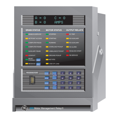
GE P50 Agile P253 User manual

GE
Grid Solutions
P50 Agile
P253
Technical Manual
Motor Protection Relay
Hardware version: A
Software version: 01
Publication reference: P253/EN M/C

Conformity
This product complies with the directive of the Council of the European Communities relating to electromagnetic
compatibility (EMC directive 2014/30/EU) and product safety (Low-voltage directive 2014/30/EU). This conformity is the result
of a test conducted in accordance with the product standard EN 60255- 26 for the EMC directive, and with the product
standard EN 60255-27 for the low voltage directive. The IED is designed in accordance with the international standards of the
IEC 60255 series.

P50 Agile P253
1 Introduction
P253/EN M/C
1-1
INTRODUCTION
CHAPTER 1

1 Introduction
P50 Agile P253
1-2
P253/EN M/C

P50 Agile P253
1 Introduction
P253/EN M/C
1-3
1 CHAPTER OVERVIEW
This chapter consists of the following sections:
1Chapter Overview
2Introduction
2.1 Features
2.1.1 Protection & Control
2.1.2 Measurement, Recording & Post Fault Analysis
2.1.3 Front Panel Interface
2.1.4 Communications
2.2 Functional Overview
2.3 Ordering Information

1 Introduction
P50 Agile P253
1-4
P253/EN M/C
2 INTRODUCTION
2.1 Features
The P253 is a dedicated motor protection relay designed to protect motors in industrial networks and
power plants. It offers essential protection functions for motors deployed in installations from LV to MV
voltage levels. The P253 relay performs an important role in many industrial processes with its
diagnostic features improving asset health monitoring.
The principal protection functions in the relay include thermal overload, negative sequence
overcurrent, loss of load, prolonged start, locked rotor (starting/normal running), restricted earth fault,
excessive no. of starts and speed switch input for stall rotor detection. Additional versatility is provided
thanks to the inclusion of backup overcurrent and earth fault protection, with up to 3 independent
stages (IEC and IEEE curve types are provided for IDMT function), breaker fail and trip circuit
supervision functions. Multiple setting groups are included. The hardware capability is broadened by a
sensitive earth fault CT option, and a universal auxiliary power supply range to permit standardisation
in procurement and inventories.
The user can assign any of the logical/physical statuses to binary inputs, binary outputs and
programmable LEDs. This provides flexibility to program the relay as per the application requirements.
All the output contacts are changeover type for ease of implementing the desired wiring schematic.
The P253 offers supervision functions including measurement, monitoring and recording. The P253
records the starting current which is very helpful in monitoring motor performance during the critical
starting period. Industry and utility protocols such as MODBUS, IEC 60870-5-103 and DNP3.0 are
available for transmitting relay data to a supervisory control system via communication networks. The
intuitive operator interface facilitates easy reading of measured values and simple configuration of the
relay.
2.1.1 Protection & Control
•Thermal overload
•Speed switch input (for stall rotor detection)
•Prolonged start (excessive long start)
•Locked rotor (during starting)
•Locked rotor (during normal running)
•Excessive number of starts
•Loss of load detection
•Negative sequence overcurrent
•Emergency restart
•Timed and instantaneous phase and earth fault protection (3 independent stages)
•Wide range of IEC/IEEE curves
•Inrush blocking
•Circuit breaker Fail
•Restricted earth Fault
•Trip circuit supervision
•6 Digital inputs
•6 Digital output (c/o)

P50 Agile P253
1 Introduction
P253/EN M/C
1-5
•1A/5A CTs selection
•SEF option
•Latching of output contacts
•Universal auxiliary power supply range
•2 Setting groups
•Password protection
•Self-supervision & internal diagnostics
2.1.2 Measurement, Recording & Post Fault Analysis
•Metering of Phase currents
•Metering of Neutral currents-derived and measured
•Measurement of thermal state
•Positive, Negative and Zero sequence current
•Load Current
•Time to Thermal trip
•Last starting current and time
•Time before a permitted start
•Authorised hot start number
•Authorised cold start number
•Motor running hours
•Total number of starts
•Total number of emergency starts
•Number of Thermal Trip
•Breaker operation counter
•Breaker trip counter
•Breaker operating time
•Up to 512 time tagged event records
•Up to 5 Fault records
•Up to 5 disturbance records
•1 start-up current record
2.1.3 Front Panel Interface
•8 LEDs for status indication
•Backlit LCD display (16 x 2)
•8 navigation keys for setting and interrogation
2.1.4 Communications
•Front USB port for real-time data viewing, device setting, and upload/download.

1 Introduction
P50 Agile P253
1-6
P253/EN M/C
•Rear EIA (RS) 485 port for SCADA communication
•Multiple protocols - Modbus/ IEC60870-5-103 or DNP3.0 (ordering option)
2.2 Functional Overview
ANSI FUNCTION P253
14 Speed switch input (for stall rotor detection) •
48 Prolonged start (excessive long start) •
51S Locked rotor (during starting) •
51L Locked rotor (during normal running) •
66 Excessive number of starts •
49 Thermal Overload •
37 Loss of load •
46 Negative sequence overcurrent •
50 Definite time overcurrent (short circuit protection) •
50N Neutral/Earth definite time overcurrent •
51 IDMT overcurrent (short circuit protection) •
51N Neutral/Earth IDMT overcurrent •
68 Inrush Blocking •
50BF Circuit breaker fail •
64R Restricted earth fault •
86 Latching of output contacts (Lockout) •
Control Functions
74 Trip circuit supervision •
Watchdog function •
Self monitoring & diagnostics •
Test/Commissioning facilities •
Emergency restart •
HMI
Back-Lit LCD display •
8 x Touch Keys
•
8 x status LEDs •
Communication
USB port •
Modbus/IEC 60870-5-103 (RS485) (or)
DNP3.0 •
Binary Input/Output
Binary Input
6
Binary Output 6 (c/o)
Analogue Input
Phase current input 3x1 ph •

P50 Agile P253
1 Introduction
P253/EN M/C
1-7
ANSI FUNCTION P253
Earth current input 1x1 ph (or)
SEF current input 1x1 ph •
General
Setting Groups 2
Self diagnostics •
Measurements •
Event records •
Fault records •
Disturbance records •
Start-up current record •
Configurable BI/BO/LEDs •
Hardware
Auxiliary supply 24-230 V AC/DC
Climatic conditions
Operating:
- 25oC to + 55oC
Storage:
-25oC to + 70oC
Housing Front IP 52
Rear IP 20

1 Introduction
P50 Agile P253
1-8
P253/EN M/C
2.3 Ordering Information
Variants 1 - 4 5678910 11 12-13 14 15
Model Type
Basic Motor Protection Relay P253
Auxilliary Voltage Binary Input Threshold Voltage
24 – 230 VDC/AC 18VDC /16VAC
1
24 – 230 VDC/AC 35VDC /33VAC
2
24 – 230 VDC/AC 77VDC /75VAC
3
24 – 230 VDC/AC 154VDC /152VAC
4
Current Transformer
Standard CT 1
SEF CT 2
Hardware Options
EIA RS485 only 1
I/O Options
Standard ( 6 logic inputs + 6 relay outputs ) A
Communication protocol
Modbus / IEC 60870-5-103
1
DNP3.0 2
Case
Non drawout A
Language
English 0
Software Reference
Initial release (v1.xx) 01
Customisation / Regionalisation
Default 0
Customer specific A
Hardware design suffix
Initial release A
Order Number
Figure 1: Ordering Information

SAFETY INFORMATION
CHAPTER 2

Safety Information
Pxxx
2

Pxxx
Safety Information
3
1 HEALTH AND SAFETY
Personnel associated with the equipment must be familiar with the contents of this Safety Information.
When electrical equipment is in operation, dangerous voltages are present in certain parts of the equipment.
Improper use of the equipment and failure to observe warning notices will endanger personnel.
Only qualified personnel may work on or operate the equipment. Qualified personnel are individuals who are:
●familiar with the installation, commissioning, and operation of the equipment and the system to which it
is being connected.
●familiar with accepted safety engineering practises and are authorised to energise and de-energise
equipment in the correct manner.
●trained in the care and use of safety apparatus in accordance with safety engineering practises
●trained in emergency procedures (first aid).
The documentation provides instructions for installing, commissioning and operating the equipment. It
cannot, however cover all conceivable circumstances. In the event of questions or problems, do not take any
action without proper authorisation. Please contact your local sales office and request the necessary
information.

Safety Information
Pxxx
4
2 SYMBOLS
Throughout this manual you will come across the following symbols. You will also see these symbols on
parts of the equipment.
Caution:
Refer to equipment documentation. Failure to do so could result in damage to
the equipment
Warning:
Risk of electric shock
Earth terminal. Note: This symbol may also be used for a protective conductor (earth) terminal if that
terminal is part of a terminal block or sub-assembly.
Protective conductor (earth) terminal
Instructions on disposal requirements
Note:
The term 'Earth' used in this manual is the direct equivalent of the North American term 'Ground'.

Pxxx
Safety Information
5
Caution:
All personnel involved in installing, commissioning, or servicing this equipment
must be familiar with the correct working procedures.
Caution:
Consult the equipment documentation before installing, commissioning, or
servicing the equipment.
Caution:
Always use the equipment as specified. Failure to do so will jeopardise the
protection provided by the equipment.
Warning:
Removal of equipment panels or covers may expose hazardous live parts. Do
not touch until the electrical power is removed. Take care when there is
unlocked access to the rear of the equipment.
Warning:
Isolate the equipment before working on the terminal strips.
Warning:
Use a suitable protective barrier for areas with restricted space, where there is a
risk of electric shock due to exposed terminals.
Caution:
Disconnect power before disassembling. Disassembly of the equipment may
expose sensitive electronic circuitry. Take suitable precautions against
electrostatic voltage discharge (ESD) to avoid damage to the equipment.
3 INSTALLATION, COMMISSIONING AND SERVICING
3.1 LIFTING HAZARDS
Many injuries are caused by:
●Lifting heavy objects
●Lifting things incorrectly
●Pushing or pulling heavy objects
●Using the same muscles repetitively
Plan carefully, identify any possible hazards and determine how best to move the product. Look at other
ways of moving the load to avoid manual handling. Use the correct lifting techniques and Personal Protective
Equipment (PPE) to reduce the risk of injury.
3.2 ELECTRICAL HAZARDS

Safety Information
Pxxx
6
Caution:
NEVER look into optical fibres or optical output connections. Always use optical
power meters to determine operation or signal level.
Caution:
Testing may leave capacitors charged to dangerous voltage levels. Discharge
capacitors by rediucing test voltages to zero before disconnecting test leads.
Caution:
Operate the equipment within the specified electrical and environmental limits.
Caution:
Before cleaning the equipment, ensure that no connections are energised. Use a
lint free cloth dampened with clean water.
Note:
Contact fingers of test plugs are normally protected by petroleum jelly, which should not be removed.
3.3 UL/CSA/CUL REQUIREMENTS
The information in this section is applicable only to equipment carrying UL/CSA/CUL markings.
Caution:
Equipment intended for rack or panel mounting is for use on a flat surface of a
Type 1 enclosure, as defined by Underwriters Laboratories (UL).
Caution:
To maintain compliance with UL and CSA/CUL, install the equipment using UL/
CSA-recognised parts for: cables, protective fuses, fuse holders and circuit
breakers, insulation crimp terminals, and replacement internal batteries.
3.4 FUSING REQUIREMENTS
Caution:
Where UL/CSA listing of the equipment is required for external fuse protection, a
UL or CSA Listed fuse must be used for the auxiliary supply. The listed
protective fuse type is: Class J time delay fuse, with a maximum current rating
of 15 A and a minimum DC rating of 250 V dc (for example type AJT15).

Pxxx
Safety Information
7
Caution:
Where UL/CSA listing of the equipment is not required, a high rupture capacity
(HRC) fuse type with a maximum current rating of 16 Amps and a minimum dc
rating of 250 V dc may be used for the auxiliary supply (for example Red Spot
type NIT or TIA).
For P50 models, use a 1A maximum T-type fuse.
For P60 models, use a 4A maximum T-type fuse.
Caution:
Digital input circuits should be protected by a high rupture capacity NIT or TIA
fuse with maximum rating of 16 A. for safety reasons, current transformer
circuits must never be fused. Other circuits should be appropriately fused to
protect the wire used.
Caution:
CTs must NOT be fused since open circuiting them may produce lethal
hazardous voltages
Warning:
Terminals exposed during installation, commissioning and maintenance may
present a hazardous voltage unless the equipment is electrically isolated.
Caution:
Tighten M4 clamping screws of heavy duty terminal block connectors to a
nominal torque of 1.3 Nm.
Tighten captive screws of terminal blocks to 0.5 Nm minimum and 0.6 Nm
maximum.
Caution:
Always use insulated crimp terminations for voltage and current connections.
Caution:
Always use the correct crimp terminal and tool according to the wire size.
Caution:
Watchdog (self-monitoring) contacts are provided to indicate the health of the
device on some products. We strongly recommend that you hard wire these
contacts into the substation's automation system, for alarm purposes.
3.5 EQUIPMENT CONNECTIONS

Safety Information
Pxxx
8
Caution:
Earth the equipment with the supplied PCT (Protective Conductor Terminal).
Caution:
Do not remove the PCT.
Caution:
The PCT is sometimes used to terminate cable screens. Always check the PCT’s
integrity after adding or removing such earth connections.
Caution:
Use a locknut or similar mechanism to ensure the integrity of stud-connected
PCTs.
Caution:
The recommended minimum PCT wire size is 2.5 mm² for countries whose
mains supply is 230 V (e.g. Europe) and 3.3 mm² for countries whose mains
supply is 110 V (e.g. North America). This may be superseded by local or
country wiring regulations.
For P60 products, the recommended minimum PCT wire size is 6 mm². See
product documentation for details.
Caution:
The PCT connection must have low-inductance and be as short as possible.
Caution:
All connections to the equipment must have a defined potential. Connections
that are pre-wired, but not used, should be earthed, or connected to a common
grouped potential.
Caution:
Check voltage rating/polarity (rating label/equipment documentation).
Caution:
Check CT circuit rating (rating label) and integrity of connections.
Caution:
Check protective fuse or miniature circuit breaker (MCB) rating.
3.6 PROTECTION CLASS 1 EQUIPMENT REQUIREMENTS
3.7 PRE-ENERGISATION CHECKLIST

Pxxx
Safety Information
9
Caution:
Check integrity of the PCT connection.
Caution:
Check voltage and current rating of external wiring, ensuring it is appropriate for
the application.
3.8 PERIPHERAL CIRCUITRY
Warning:
Do not open the secondary circuit of a live CT since the high voltage produced
may be lethal to personnel and could damage insulation. Short the secondary of
the line CT before opening any connections to it.
Note:
For most General Electric equipment with ring-terminal connections, the threaded terminal block for current
transformer termination is automatically shorted if the module is removed. Therefore external shorting of the CTs
may not be required. Check the equipment documentation and wiring diagrams first to see if this applies.
Caution:
Where external components such as resistors or voltage dependent resistors
(VDRs) are used, these may present a risk of electric shock or burns if touched.
Warning:
Take extreme care when using external test blocks and test plugs such as the
MMLG, MMLB and P990, as hazardous voltages may be exposed. Ensure that CT
shorting links are in place before removing test plugs, to avoid potentially lethal
voltages.
3.9 UPGRADING/SERVICING
Warning:
Do not insert or withdraw modules, PCBs or expansion boards from the
equipment while energised, as this may result in damage to the equipment.
Hazardous live voltages would also be exposed, endangering personnel.
Caution:
Internal modules and assemblies can be heavy and may have sharp edges. Take
care when inserting or removing modules into or out of the IED.

Safety Information
Pxxx
10
4 DECOMMISSIONING AND DISPOSAL
Caution:
Before decommissioning, completely isolate the equipment power supplies
(both poles of any dc supply). The auxiliary supply input may have capacitors in
parallel, which may still be charged. To avoid electric shock, discharge the
capacitors using the external terminals before decommissioning.
Caution:
Avoid incineration or disposal to water courses. Dispose of the equipment in a
safe, responsible and environmentally friendly manner, and if applicable, in
accordance with country-specific regulations.
Table of contents
Other GE Relay manuals