manuals.online logo
Brands
  1. Home
  2. •
  3. Brands
  4. •
  5. Toshiba
  6. •
  7. Relay
  8. •
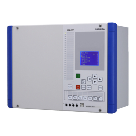
  9. Toshiba GRZ100-211B User manual

Toshiba GRZ100-211B User manual

6F2S0834
INSTRUCTION MANUAL
DISTANCE RELAY
WITH INTEGRAL DIGITAL COMMUNICATION
GRZ100 - 211B, 214B, 216B, 311B
- 221B, 224B, 226B, 321B, 323B
©TOSHIBA Corporation 2005
All Rights Reserved.
( Ver. 0.3 )
www . ElectricalPartManuals . com
1
6F2S0834
Safety Precautions
Before using this product, please read this chapter carefully.
This chapter describes the safety precautions recommended when using the GRZ100. Before
installing and using the equipment, this chapter must be thoroughly read and understood.
Explanation of symbols used
Signal words such as DANGER, WARNING, and two kinds of CAUTION, will be followed by
important safety information that must be carefully reviewed.
Indicates an imminently hazardous situation which will result in death or
serious injury if you do not follow the instructions.
Indicates a potentially hazardous situation which could result in death or
serious injury if you do not follow the instructions.
CAUTION Indicates a potentially hazardous situation which if not avoided, may result in
minor injury or moderate injury.
CAUTION Indicates a potentially hazardous situation which if not avoided, may result in
property damage.
DANGE
R
WARNING
www . ElectricalPartManuals . com
2
6F2S0834
•Current transformer circuit
Never allow the current transformer (CT) secondary circuit connected to this equipment to be
opened while the primary system is live. Opening the CT circuit will produce a dangerously high
voltage.
•Exposed terminals
Do not touch the terminals of this equipment while the power is on, as the high voltage generated
is dangerous.
•Residual voltage
Hazardous voltage can be present in the DC circuit just after switching off the DC power supply. It
takes about 30 seconds for the voltage to discharge.
•Fiber optic
Invisible laser radiation
Do not view directly with optical instruments.
Class 1M laser product
- the maximum output of laser radiation: 0.2 mW
- the pulse duration: 79.2 ns
- the emitted wavelength(s): 1310 nm
CAUTION
•Earth
The earthing terminal of the equipment must be securely earthed.
CAUTION
•Operating environment
The equipment must only be used within the range of ambient temperature, humidity and dust, etc.
detailed in the specification and in an environment free of abnormal vibration.
•Ratings
Before applying AC voltage and current or the DC power supply to the equipment, check that they
conform to the equipment ratings.
•Printed circuit board
Do not attach and remove printed circuit boards when the DC power to the equipment is on, as this
may cause the equipment to malfunction.
•External circuit
When connecting the output contacts of the equipment to an external circuit, carefully check the
supply voltage used in order to prevent the connected circuit from overheating.
DANGE
R
WARNING
www . ElectricalPartManuals . com
3
6F2S0834
•Connection cable
Carefully handle the connection cable without applying excessive force.
•Modification
Do not modify this equipment, as this may cause the equipment to malfunction.
•Short-link
Do not remove a short-link which is mounted at the terminal block on the rear of the relay before
shipment, as this may cause the performance of this equipment such as withstand voltage, etc., to
reduce.
•Disposal
When disposing of this equipment, do so in a safe manner according to local regulations.
www . ElectricalPartManuals . com
4
6F2S0834
Contents
Safety Precautions 1
1. Introduction 9
2. Application Notes 12
2.1 Power System Protection - Basic Concepts 12
2.1.1 The Function of The Protection Relay 12
2.1.2 Protection Relay Requirements 12
2.1.3 Main Protection and Backup Protection 14
2.1.4 Distance Relay - General Performance 14
2.1.5 Power Swing and Out-of-Step 15
2.2 Principle of Distance Measurement 17
2.2.1 Phase Fault 17
2.2.2 Earth Fault 18
2.3 Multi-Terminal Line Protection 20
2.3.1 Increased Use of Multi-Terminal Lines 20
2.3.2 Protection Problems on Three-Terminal Application 20
2.3.3 Three-Terminal Line Protection 22
2.4 Protection Scheme 24
2.4.1 Time-Stepped Distance Protection 24
2.4.2 Zone 1 Extension Protection 40
2.4.3 Command Protection 43
2.4.4 High-Resistance Earth Fault Protection 60
2.4.5 Overcurrent Backup Protection 67
2.4.6 Thermal Overload Protection 71
2.4.7 Switch-Onto-Fault Protection 73
2.4.8 Stub Protection 75
2.4.9 Overvoltage and Undervoltage Protection 76
2.4.10 Broken Conductor Protection 83
2.4.11 Transfer Trip Function 86
2.4.12 Breaker Failure Protection 88
2.4.13 Out-of-Step Protection 91
2.4.14 Voltage Transformer Failure Supervision 93
2.4.15 Power Swing Blocking 95
2.4.16 Tripping Output Signals 99
2.5 Communication System 100
2.5.1 Integral Digital Communication Interface 100
2.5.2 External Communication Interface 110
2.6 Characteristics of Measuring Elements 113
2.6.1 Distance Measuring Elements Z1, Z1X, Z2, ZF, Z3, Z4, ZR1, ZR2, ZND
and PSB 113
2.6.2 Phase Selection Element UVC 121
2.6.3 Directional Earth Fault Elements DEFF and DEFR 122
www . ElectricalPartManuals . com
5
6F2S0834
2.6.4 Inverse Definite Minimum Time Overcurrent Element IDMT 123
2.6.5 Out-of-Step Element OST 124
2.6.6 Voltage and Synchronism Check Elements OVL, UVL, OVB, UVB, and
SYN 125
2.6.7 Current Change Detection Elements OCD and OCDP 126
2.6.8 Negative Sequence Directional Elements DOCNF and DOCNR 127
2.6.9 Level Detectors 128
2.7 Autoreclose 129
2.7.1 Application 129
2.7.2 Scheme Logic 131
2.7.3 Setting 141
2.7.4 Autoreclose Output Signals 144
2.8 Fault Locator 145
2.8.1 Application 145
2.8.2 Starting Calculation 146
2.8.3 Displaying Location 146
2.8.4 Distance to Fault Calculation 146
2.8.5 Setting 150
3. Technical Description 152
3.1 Hardware Description 152
3.1.1 Outline of Hardware Modules 152
3.1.2 Transformer Module 156
3.1.3 Signal Processing Module 157
3.1.4 Binary Input and Output Module 158
3.1.5 Human Machine Interface (HMI) Module 163
3.2 Input and Output Signals 165
3.2.1 Input Signals 165
3.2.2 Binary Output Signals 169
3.2.3 PLC (Programmable Logic Controller) Function 170
3.3 Automatic Supervision 171
3.3.1 Basic Concept of Supervision 171
3.3.2 Relay Monitoring and Testing 171
3.3.3 CT Circuit Current Monitoring 172
3.3.4 Signal Channel Monitoring for Integral Digital Communication 172
3.3.5 Signal Channel Monitoring and Testing for External Communication 173
3.3.6 Relay Address Monitoring 174
3.3.7 Disconnector Monitoring 174
3.3.8 Failure Alarms 174
3.3.9 Trip Blocking 175
3.3.10 Setting 176
3.4 Recording Function 178
3.4.1 Fault Recording 178
3.4.2 Event Recording 180
3.4.3 Disturbance Recording 180
3.5 Metering Function 182
www . ElectricalPartManuals . com
6
6F2S0834
4. User Interface 183
4.1 Outline of User Interface 183
4.1.1 Front Panel 183
4.1.2 Communication Ports 185
4.2 Operation of the User Interface 187
4.2.1 LCD and LED Displays 187
4.2.2 Relay Menu 189
4.2.3 Displaying Records 192
4.2.4 Displaying Status Information 197
4.2.5 Viewing the Settings 202
4.2.6 Changing the Settings 203
4.2.7 Testing 227
4.3 Personal Computer Interface 234
4.4 Relay Setting and Monitoring System 234
4.5 IEC 60870-5-103 Interface 235
4.6 Clock Function 235
5. Installation 236
5.1 Receipt of Relays 236
5.2 Relay Mounting 236
5.3 Electrostatic Discharge 236
5.4 Handling Precautions 236
5.5 External Connections 237
6. Commissioning and Maintenance 239
6.1 Outline of Commissioning Tests 239
6.2 Cautions 240
6.2.1 Safety Precautions 240
6.2.2 Cautions on Tests 240
6.3 Preparations 241
6.4 Hardware Tests 242
6.4.1 User Interfaces 242
6.4.2 Binary Input Circuit 243
6.4.3 Binary Output Circuit 244
6.4.4 AC Input Circuits 245
6.5 Function Test 246
6.5.1 Measuring Element 246
6.5.2 Timer Test 265
6.5.3 Protection Scheme 266
6.5.4 Metering and Recording 272
6.5.5 Fault Locator 272
6.6 Conjunctive Tests 273
6.6.1 On Load Test 273
6.6.2 Signaling Circuit Test 273
6.6.3 Tripping and Reclosing Circuit Test 275
6.7 Maintenance 277
www . ElectricalPartManuals . com
7
6F2S0834
6.7.1 Regular Testing 277
6.7.2 Failure Tracing and Repair 277
6.7.3 Replacing Failed Modules 279
6.7.4 Resumption of Service 281
6.7.5 Storage 281
7. Putting Relay into Service 282
www . ElectricalPartManuals . com
8
6F2S0834
Appendix A Block Diagrams 283
Appendix B Signal List 287
Appendix C Variable Timer List 323
Appendix D Binary Input/Output Default Setting List 325
Appendix E Details of Relay Menu and LCD & Button Operation 333
Appendix F Case Outline 343
Appendix G External Connections 351
Appendix H Relay Setting Sheet 357
Appendix I Commissioning Test Sheet (sample) 383
Appendix J Return Repair Form 389
Appendix K Technical Data 395
Appendix L Symbols Used in Scheme Logic 407
Appendix M Example of Setting Calculation 411
Appendix N IEC60870-5-103: Interoperability 423
Appendix O Programmable Reset Characteristics and Implementation of
Thermal Model to IEC60255-8 435
Appendix P Data Transmission Format 439
Appendix Q Relay Operation under Communication Failure in Backup Carrier
Scheme 443
Appendix R Inverse Time Characteristics 447
Appendix S Failed Module Tracing and Replacement 451
Appendix S Ordering 459
The data given in this manual are subject to change without notice. (Ver.0.3)
www . ElectricalPartManuals . com
9
6F2S0834
1. Introduction
GRZ100 is a fully numeric distance protection incorporating integral digital communication
channels for teleprotection signalling. Either one or two communication channels are provided,
suitable for relay-to-relay connection via fibre-optic links, or via electrical interfaces to a digital
communication network. GRZ100 can be configured using the integral communication channels
to support the following functions:
- Phase-segregated command protection distance schemes (PUP, POP, BOP and UOP with
week infeed and current reversal logic).
- Phase-segregated command protection DEF schemes (POP, BOP and UOP).
- Command protection signalling for tripping during a power swing.
- Command protection for 2- or 3-terminal applications.
- Single-phase autoreclosing available for carrier tripping.
- Phase-segregated transfer trip (intertripping).
- Transmission of binary signals for user-configurable applications.
- Transmission of measured values to be displayed at the remote terminals.
- Synchronisation of the clocks at the various terminals.
- Fault-location by use of remote-end data in the case of 3-terminal applications.
- Continuous monitoring of the communication channels, with capability to provide
dual-redundant channels in the case of a 2-ended system, and automatic re-routing of signals
in the event of a communication channel failure in a 3-ended system.
GRZ100 can be also applied with conventional external communication channels.
Other features of GRZ100 are as follows:
GRZ100 provides the following protection schemes.
- Time-stepped distance protection with four forward zones, three reverse zones, and one
non-directional zone
- Zone 1 extension protection
- High-resistance earth fault protection
- Broken conductor detection
- Overcurrent backup protection
- Thermal overload protection
- Switch-on-to-fault and stub protection
- Breaker failure protection
- Out-of-step trip protection
- Power swing blocking
The GRZ100 actuates high-speed single-shot autoreclose or multi-shot autoreclose.
The GRZ100 is a member of the G-series family of numerical relays which utilise common
hardware modules with the common features:
www . ElectricalPartManuals . com
10 
6F2S0834
The GRZ100 provides the following metering and recording functions.
- Metering
- Fault record
- Event record
- Fault location
- Disturbance record
The GRZ100 provides the following menu-driven human interfaces for relay setting or viewing of
stored data.
- Relay front panel; 4 ×40 character LCD, LED display and operation keys
- Local PC
- Remote PC
Password protection is provided to change settings. Eight active setting groups are provided. This
allows the user to set one group for normal operating conditions while other groups may be set to
cover alternative operating conditions.
GRZ100 provides either two or three serial ports, and an IRIG-B port for an external clock
connection. A local PC can be connected via the RS232C port on the front panel of the relay.
Either one or two rear ports (RS485 or fibre optic) are provided for connection to a remote PC and
for IEC60870-5-103 communication with a substation control and automation system. Further,
Ethernet LAN port can be provided as option.
Further, the GRZ100 provides the following functions.
- Configurable binary inputs and outputs
- Programmable logic for I/O configuration, alarms, indications, recording, etc.
- Automatic supervision
The GRZ100 has the following models:
Relay Type and Model
Relay Type:
- Type GRZ100; Numerical distance relay
Relay Model:
- For two terminal line, With autoreclose for single breaker scheme
•Model 211B; 18 binary inputs, 22 binary outputs, 6 binary outputs for tripping
•Model 214B; 22 binary inputs, 18 binary outputs, 3 binary outputs for tripping
•Model 216B; 25 binary inputs, 36 binary outputs, 3 binary outputs for tripping
- For two terminal line, With autoreclose for one-and-a-half breaker scheme
•Model 311B; 18 binary inputs, 22 binary outputs, 6 binary outputs for tripping
- For three terminal line, With autoreclose for single breaker scheme
•Model 221B; 18 binary inputs, 22 binary outputs, 6 binary outputs for tripping
•Model 224B; 22 binary inputs, 18 binary outputs, 3 binary outputs for tripping
•Model 226B; 25 binary inputs, 36 binary outputs, 3 binary outputs for tripping
- For three terminal line, With autoreclose for one-and-a-half breaker scheme
•Model 321B; 18 binary inputs, 22 binary outputs, 6 binary outputs for tripping
•Model 323B; 18 binary inputs, 40 binary outputs, 6 binary outputs for tripping
www . ElectricalPartManuals . com
11 
6F2S0834
Table 1.1.1 shows the measuring elements incorporated.
Table 1.1.1 Incorporated Measuring Elements
Measuring elements 211B,
214B, 216B 311B 221B,
224B, 226B 321B, 323B
Z1S, Z1SX, Z2S, Z3S, ZFS,
ZR1S, ZR2S, Z4S, ZNDS
Distance element (phase fault) 9999
Z1G, Z1GX, Z2G, Z3G, ZFG,
ZR1G, ZR2G, Z4G, ZNDG
Distance element (earth fault) 9999
UVC Phase selection element 9999
DEFF, DEFR Directional earth fault element 9999
OC, OCI Overcurrent element (phase fault) 9999
EF, EFI Overcurrent element (earth fault) 9999
SOTF (OCH) Switch-onto-fault protection 9999
THM Thermal overload protection 9999
VTF (OVG, UVF, OCD) VT failure supervision 9999
PSBS, PSBG Power swing blocking 9999
OST Out-of-step tripping
9999
BF Breaker failure protection 9999
FL Fault locator
9999
ARC (SYN, UV, OV) Autoreclose function 1CB 2CB 1CB 2CB
OVS1,OVS2,OVG1,OVG2,
UVS1,UVS2,UVG1,UVG2
Overvoltage & undervoltage
protection
9999
BCD Broken conductor detection 9999
Z4S and Z4G are not for backup protection and used for command protection.
www . ElectricalPartManuals . com
12 
6F2S0834
2. Application Notes
2.1 Power System Protection - Basic Concepts
2.1.1 The Function of The Protection Relay
The protection relay, which protects the power system from various faults, plays an extremely
important role in power system stability. Its main functions are as follows:
Prevention of power supply interruption:
Fault clearance and resumption of healthy power transmission as soon as
possible.
Prevention of damage to equipment:
Consecutive system faults will eventually lead to damage to primary
plant, for example destruction of insulators, rupture of lines, burning of
transformers, etc. The protection relay can help prevent such damage to
equipment.
Prevention of system instability:
is necessary to remove Power system faults at high speed by using
protection relays as the existence of a system fault for an extended period
of time may initiate a generator out-of-step condition.
2.1.2 Protection Relay Requirements
The protection relay, which plays the important role of protecting the power system from faults,
must meet several requirements. These requirements can be summarized as follows:
a) Selectivity: All faults that occur on the power system should be removed but at the same time
it must be ensured that only the minimum section of the power system must be
isolated in order to clear the fault. Figure 2.1.2.1 shows typical different
protection zones on the power system. In order to provide complete coverage by
the protection, the neighboring protection zones are set to overlap. Figure 2.1.2.2
shows the relationship between the circuit breaker and CT locations. In Figure
(a), the CTs are installed on both sides of the circuit breaker, one for line
protection and the other for busbar protection, enabling the protection coverage
to overlap. Figure (b) shows the case where the same CT is used for both the line
protection and busbar protection. In this case, the line protection would operate
for a fault which occurred midway between the CT and circuit breaker, but the
busbar protection would not operate, thus failing to remove the fault. It is
important to prevent blind spots in power system protection design.
b) High speed: In order to avoid damage to equipment or power system instability, it is
important to shorten the duration of faults by applying high-speed protection
relays. The GRZ100 has a minimum operating time of 18 ms. However, the
operating time of the circuit breaker and transmission delay in the case of carrier
protection, etc. must also be taken into consideration.
www . ElectricalPartManuals . com
13 
6F2S0834
Figure 2.1.2.1 Protection Zones
(a) (b)
Figure 2.1.2.2 Protection Zone and CB, CT
c) Reliability: The protection relay is normally in a quiescent state and is available to respond to
faults that may occur on the power system in the protection zone.
In order that this may be achieved the availability of the protection relay is
checked even in its quiescent state.
A fundamental requirement to ensure that the reliability of the protection relay is
high is that its components must be extremely reliable. This can be achieved by
using high quality components and reducing the number of components. The
GRZ100 reduces the number of parts by using state-of-the-art highly integrated
semiconductor components.
To maintain high reliability, not only must the relay have a robust hardware
structure but it is also important to detect any fault immediately and not to leave
the relay in a faulted state for prolonged periods. Therefore, the GRZ100 is
equipped with an automatic supervision function. Whenever a hardware fault
occurs, an alarm is issued to inform the operator of the problem to permit
remedial action.
In order to dramatically improve the operating reliability of the relay in the event
of a system fault, there are two options: to use a protection relay with a
duplicated protection system or to provide an additional fault detection relay
within the relay with AND logic.
Line Line
BusbarBusbar
:Circuit Breaker
Busbar
BusbarBusbar
Line Line
www . ElectricalPartManuals . com
14 
6F2S0834
2.1.3 Main Protection and Backup Protection
The power system protection system generally consists of a main protection and a backup
protection to reliably remove all faults. In principle, system faults must be removed in the shortest
possible time and cause the minimum outage. This important function is served by the main
protection. In distance protection, this function is served by the zone 1 element and command
protection, etc. However, the main protection may not always function perfectly. For example, the
main protection relay may not be able to function correctly due to a power supply failure, CVT
failure, data transmission device failure, circuit breaker failure or failure of the main protection
relay itself. In such cases, power system integrity depends on the backup protection.
The backup protection provides power system protection with a set time delay, its timer value is
set in a range that allows coordination with the main protection. To achieve time coordination with
the main protection, the time delay of the backup protection is determined with a margin in
consideration of the following factors:
•Operating time of main protection relay
•Operating time of circuit breaker
•Reset time of backup protection relay
There are two types of backup protection: remote backup protection that provides backup from a
remote substation at a different location to the main protection, and local backup protection
installed in the same location as that of the main protection that provides backup from that
substation.
Each of these protections has the following features:
Remote backup protection: Possible causes for main protection failures include relay faults,
power supply faults, and various other factors. It is therefore
important to provide backup protection from a remote substation to
prevent the backup protection from failing due to the same causes as
the local main protection. The zone 2 and zone 3 elements of distance
relays, etc. provide as these remote backup protection functions.
Local backup protection: Provides backup protection at the same substation as that of the main
protection and often has the purpose of providing backup when the
circuit breaker fails to operate.
2.1.4 Distance Relay - General Performance
For distance relays, the reach of the zone 1 protection is usually set to approximately 80 to 90% of
the length of the transmission line. This is to ensure that overreach tripping does not occur for
external faults that occur beyond the busbar at the remote end. For internal faults that occur
beyond the reach of zone 1, time delayed tripping by the zone 2 element is applied. High-speed
tripping can be achieved by means of a "command protection system" that exchanges relay
operation information with the remote end.
There are various causes for measuring errors in a distance relay. In the case of a fault with
resistance, the reactance component seen by the relay at the power sending terminal is smaller than
the actual value and it tends to overreach. On the contrary, the reactance component seen by the
relay at the power receiving terminal is greater than the actual value and it tends to underreach.
The line impedance has different values in different phases. When its average value is used for the
relay setting, underreach will occur in a phase with a greater impedance than the average value. In
the case of fault resistance, its impedance is greater for earth faults where the fault is grounded via
a steel tower or tree rather than a phase fault consisting of arc resistance only. Therefore,
measuring errors in the earth fault relay are generally greater than those in the phase fault relay.
The fault arc is considered to be almost equivalent to pure resistance. But if the phase of a current
that flows into a fault point from the remote end is different from the phase of the local current, the
www . ElectricalPartManuals . com
15 
6F2S0834
voltage at the fault will have a phase angle difference with respect to the local current, producing a
measuring error in the distance relay with the principle of measuring the reactance component.
The existence of a zero-sequence current on the protected line and adjacent line can also cause
errors in the earth fault relay. The zero-sequence current normally acts in the direction of relay
underreaching due to the effect of the induced voltage. The compensation method will be
described in detail in the next section. The earth fault relay contains more errors than the phase
fault relays even with these compensation methods. Therefore, the earth fault relays are usually set
with a greater margin than the phase fault relays.
Regarding protection relay measuring errors, it is also necessary to consider hardware errors in the
relay itself, errors introduced by coupling capacitor voltage transformers (CCVT), and transient
overreach errors caused by the DC component of the fault current. For GRZ100, the total of these
errors is specified to be less than 5%.
2.1.5 Power Swing and Out-of-Step
Power swings occur when the output voltages of generators at different points in the power system
slip relative to each other, as a result of system instabilities which may be caused by sudden
changes in load magnitude or direction, or by power system faults and their subsequent clearance.
During the course of such a power swing, the impedance seen by a distance relay may move
(relatively slowly) from the load area into the distance protection operating characteristic. In fact,
this phenomenon appears to the distance protection measuring elements like a three phase fault
condition and may result in tripping if no countermeasure is applied. Most power swings are
transient conditions from which the power system can recover after a short period of time, and
distance protection tripping is therefore highly undesirable in such cases. GRZ100 provides a
power swing blocking function (PSB) to prevent unwanted tripping during a power swing. Figure
2.1.5.1 illustrates the typical impedance locus as seen by a distance relay during a transient power
swing.
Figure 2 1.5.1 Impedance Locus during Transient Power Swing
A special case of the power swing condition occurs when the power system disturbance is so
severe that generators lose synchronism with each other and are said to be out-of-step. During an
out-of-step condition the phase angle between generators continues to increase and pass through
180°, at which point a distance relay measures an impedance equal to that for a three phase fault at
the centre of the power system. The impedance locus typically describes an arc passing through
the electrical centre, as shown in Figure 2.1.5.2.
X
R
Load Area
Distance protection
characteristic (Mho)
Impedance locus during
transient power swing
www . ElectricalPartManuals . com
16 
6F2S0834
Figure 2.1.5.2 Impedance Locus during Out-of-Step Condition
In the case of a full out-of-step condition (as opposed to a transient power swing) it is desirable to
separate the system in the vicinity of the centre of the out-of-step condition. GRZ100 provides an
out-of-step detection element (OST) which can provide tripping in these circumstances.
Although the power swing and out-of-step conditions are very closely related (in fact one is
simply the most severe form of the other), completely different actions are required from the
protection relay. The PSB function must ensure stability of the distance protection during transient
power system conditions, while the OST element initiates system separation by tripping in the
event that a severe power swing results in potentially irrecoverable loss of stability in the power
system. The PSB and OST elements are therefore completely separate functions within the
GRZ100 relay, with different characteristics, separate scheme logic and different settings.
X
R
Load Area
Distance protection
characteristic (Mho)
Impedance locus during
out-of-step condition
www . ElectricalPartManuals . com
17 
6F2S0834
2.2 Principle of Distance Measurement
2.2.1 Phase Fault
The phase-fault distance relay measures the impedance from the relay to the fault point using a
delta voltage and current. The positive-sequence impedance is used as the line impedance. The
principle is described below.
Figure 2.2.1.1 shows the circuit in the event of a two-phase fault. Suppose that the impedance from
the relay to the fault is the same in both phase B and phase C, and that the self impedance is Zsand
the mutual impedance between phases is Zm. If the voltages and currents of phase B and phase C
are Vb, Vc, Iband Icand the fault point voltage is VF, then Vband Vcare given by the following
equations.
V
b= Zs×Ib+ Zm×Ic+ VF....................... (2-1)
V
c= Zs×Ic+ Zm×Ib+ VF....................... (2-2)
From equations (2-1) and (2-2), the following equation is obtained.
Vb−Vc= (Zs−Zm) ×(Ib−Ic) ......................... (2-3)
where,
Z
s: Self impedance
Z
m: Mutual impedance
Since the effect of the phase A current is small and is almost canceled when introducing equation
(2-3), it is omitted in equations (2-1) and (2-2).
When each phase of the line is symmetric to the other, the positive-sequence and zero-sequence
impedance Z1and Z0according to the method of symmetrical components are defined by the
following equations, using self impedance Zsand mutual impedance Zm:
Z1 = Zs −Zm ............................................... (2-4)
Z0 = Zs + 2Zm ............................................. (2-5)
where,
Z1: Positive-sequence impedance
Z0: Zero-sequence impedance
Equation (2-3) can be rewritten as follows:
Z
1= (Vb−Vc)/(Ib−Ic) .............................. (2-6)
As shown above, the positive-sequence impedance is used for the phase fault relay setting.
Figure 2.2.1.1 Two-Phase Fault
Va
Zs
VF
VF
Vb
ib
Vc
ic
Zm
www . ElectricalPartManuals . com
18 
6F2S0834
2.2.2 Earth Fault
Figure 2.2.2.1 shows the circuit in the event of a single-phase earth fault. It is not simple to exactly
measure the distance up to the fault point for a single-phase earth fault.
This is because the impedance of the zero-sequence circuit including the earth return is generally
different from the positive-sequence impedance. Therefore, the faulted phase voltage is not simply
proportional to the faulted phase current.
Figure 2.2.2.1 Single-Phase Earth Fault
It is necessary to analyze the impedance seen by the relay in the event of a single-phase earth fault
according to the method of symmetrical components. Figure 2.2.2.2 shows an equivalent circuit
for the single-phase earth fault based on the method of symmetrical components. Assuming the
positive-sequence, negative-sequence and zero-sequence voltages are V1F, V2F and V0F, the
voltage at the relay point of each symmetrical circuit is given by the following equation. However,
suppose that the positive-sequence impedance and negative-sequence impedance are the same and
influences of the fault resistance are ignored.
V
1= Z1×I1+ V1F ..................................... (2-7)
V
2 = Z1×I2 + V2F ..................................... (2-8)
V
0= Z0×I0+ Z0m ×I0m + V0F............... (2-9)
where, V1: Relay point positive-sequence voltage
V
2: Relay point negative-sequence voltage
V
0: Relay point zero-sequence voltage
V
1F: Fault point positive-sequence voltage
V
2F: Fault point negative-sequence voltage
V
0F: Fault point zero-sequence voltage
I
1: Relay point positive-sequence current
I
2: Relay point negative-sequence current
I
0: Relay point zero-sequence current
I
0m: Adjacent line zero-sequence current
Z
1: Fault point - relay point positive-sequence impedance
Z
0: Fault point - relay point zero-sequence impedance
Z
0m:Adjacent line zero-sequence mutual impedance
Taking account of the fact that the faulted phase voltage VaF at the point of fault is,
VaF = V1F + V2F + V0F = 0......................................... (2-10)
phase A voltage Vaat the relay is calculated from the following equation:
ia
vaF
va
vb
vc
www . ElectricalPartManuals . com
19 
6F2S0834
Va= V1+ V2+ V0
= Z1(Ia+ (Z0−Z1)/Z1×I0+ Z0m/Z1×I0m) ...... (2-11)
Where, Iais the current at phase "a" relay point and is defined in the following equation by the
symmetrical component of the current:
Ia= I1+ I2+ I0.............................................................. (2-12)
Here, defining the current synthesized by the phase "a" relay as Ia', and
Ia' = Ia+ (Z0−Z1)/Z1×I0+ Z0m/Z1×I0m................ (2-13)
then equation (2-11) can be rewritten as the following equation:
Va= Z1×Ia'................................................................... (2-14)
That is, positive-sequence impedance Z1up to the fault point can be obtained from the simple ratio
of phase "a" voltage Vato compensated current Ia' according to equation (2-14).
Obtaining the compensated current according to equation (2-13) is called "zero-sequence
compensation." Note in this zero-sequence compensation, the compensation coefficient (Z0−
Z1)/Z1and Z0m/Z1are not real numbers, but complex numbers. The GRZ100 relay has a
configuration that allows this compensation coefficient to be set as a complex number and setting
the coefficient correctly makes it possible to measure exactly the distance up to the fault point.
In equations (2-7) to (2-9), the fault resistance was ignored. Since the measurement of the distance
up to the fault point based on equation (2-14) is carried out using the reactance component, in
principle there is no influence on the voltage component due to the fault resistance. However,
under real operating conditions, distance measurement errors are produced as a result of the fault
resistance combined with the power flow or the current flowing into the fault point from the point
opposite the relay location.
Figure 2.2.2.2 Equivalent Circuit of Single-Phase Earth Fault
V1V1F
V0F
V2F
Z1
I1
V2
I2
V0
I0
Z1
Z0
Negative-sequence circuit
Zero-sequence circuit
Positive-sequence circuit
www . ElectricalPartManuals . com
This manual suits for next models

8

Other Toshiba Relay manuals

Toshiba Current Relay RC803A-HP1 User manual

Toshiba

Toshiba Current Relay RC803A-HP1 User manual

Toshiba GRD110 User manual

Toshiba

Toshiba GRD110 User manual

Toshiba GRZ100 B Series User manual

Toshiba

Toshiba GRZ100 B Series User manual

Toshiba S2E21 User manual

Toshiba

Toshiba S2E21 User manual

Toshiba BMS-IFWH5E User manual

Toshiba

Toshiba BMS-IFWH5E User manual

Toshiba GR 200 Series User manual

Toshiba

Toshiba GR 200 Series User manual

Toshiba GRL150-100 Series User manual

Toshiba

Toshiba GRL150-100 Series User manual

Toshiba GRT100 Series User manual

Toshiba

Toshiba GRT100 Series User manual

Toshiba GRL100-101A User manual

Toshiba

Toshiba GRL100-101A User manual

Toshiba BMS-IFWH5UL User manual

Toshiba

Toshiba BMS-IFWH5UL User manual

Toshiba GRD130 User manual

Toshiba

Toshiba GRD130 User manual

Toshiba BMS-IFDD03UL User manual

Toshiba

Toshiba BMS-IFDD03UL User manual

Toshiba GRD150 User manual

Toshiba

Toshiba GRD150 User manual

Toshiba GRD150 User manual

Toshiba

Toshiba GRD150 User manual

Toshiba GRZ100 User manual

Toshiba

Toshiba GRZ100 User manual

Toshiba RC820-HP-Y User manual

Toshiba

Toshiba RC820-HP-Y User manual

Toshiba GRD130-210 User manual

Toshiba

Toshiba GRD130-210 User manual

Popular Relay manuals by other brands

Pepperl+Fuchs KFD2-RSH-1.2D.FL2 Original instructions

Pepperl+Fuchs

Pepperl+Fuchs KFD2-RSH-1.2D.FL2 Original instructions

ASO Safety Solutions ISK 74-312 operating manual

ASO Safety Solutions

ASO Safety Solutions ISK 74-312 operating manual

GEYA GRT8-D instruction manual

GEYA

GEYA GRT8-D instruction manual

ABB DB42 installation instructions

ABB

ABB DB42 installation instructions

F&F BIS-411i quick start guide

F&F

F&F BIS-411i quick start guide

Eaton Power Xpert C445 user manual

Eaton

Eaton Power Xpert C445 user manual

MerCs ME-ELF-AF user manual

MerCs

MerCs ME-ELF-AF user manual

Leviton EZ-MAX Plus 16 quick start guide

Leviton

Leviton EZ-MAX Plus 16 quick start guide

Eaton EMR-4000 Installation, operation and maintenance

Eaton

Eaton EMR-4000 Installation, operation and maintenance

Velleman VM129 user guide

Velleman

Velleman VM129 user guide

Bpt VLS/101 installation instructions

Bpt

Bpt VLS/101 installation instructions

GE Multilin MIWII instruction manual

GE

GE Multilin MIWII instruction manual

sprecher + schuh CA7-9 23 Series Installation instruction

sprecher + schuh

sprecher + schuh CA7-9 23 Series Installation instruction

GE CEX57D instructions

GE

GE CEX57D instructions

Maker Factory MAKEVMA400 user manual

Maker Factory

Maker Factory MAKEVMA400 user manual

Contrel ELR-51AS instruction manual

Contrel

Contrel ELR-51AS instruction manual

Ribind ACQ9081 quick start guide

Ribind

Ribind ACQ9081 quick start guide

Greystone CSR-112 installation guide

Greystone

Greystone CSR-112 installation guide

manuals.online logo
manuals.online logoBrands
  • About & Mission
  • Contact us
  • Privacy Policy
  • Terms and Conditions

Copyright 2025 Manuals.Online. All Rights Reserved.