manuals.online logo
Brands
  1. Home
  2. •
  3. Brands
  4. •
  5. Toshiba
  6. •
  7. Relay
  8. •
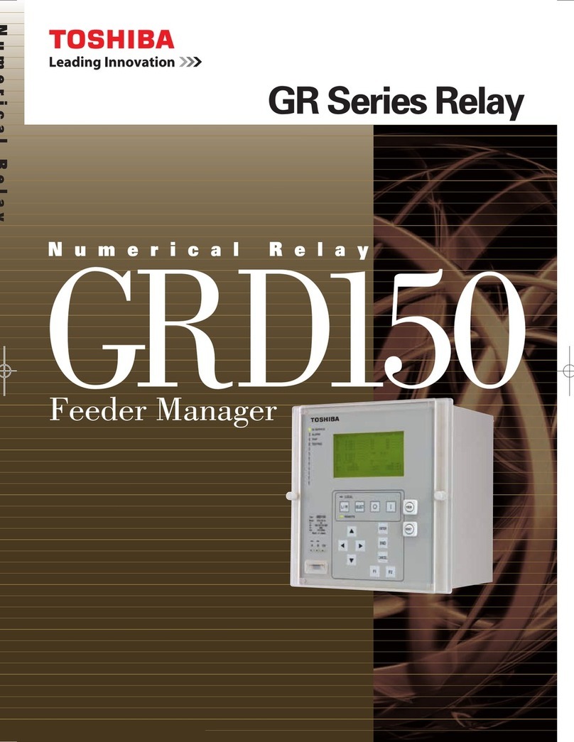
  9. Toshiba GRD150 User manual

Toshiba GRD150 User manual

6F2S0842
INSTRUCTION MANUAL
FEEDER MANAGER
GRD150
©TOSHIBA Corporation 2005
All Rights Reserved.
(Ver. 0.6)
⎯ 1⎯
6F2S0842
Safety Precautions
Before using this product, please read this chapter carefully.
This chapter describes the safety precautions recommended when using the GRD150. Before
installing and using the equipment, this chapter must be thoroughly read and understood.
Explanation of symbols used
Signal words such as DANGER, WARNING, and two kinds of CAUTION, will be followed by
important safety information that must be carefully reviewed.
Indicates an imminently hazardous situation which will result in death or
serious injury if you do not follow the instructions.
Indicates a potentially hazardous situation which could result in death or
serious injury if you do not follow the instructions.
CAUTION Indicates a potentially hazardous situation which if not avoided, may result in
minor injury or moderate injury.
CAUTION Indicates a potentially hazardous situation which if not avoided, may result in
property damage.
DANGE
R
WARNING
⎯ 2⎯
6F2S0842
•Current transformer circuit
Never allow the current transformer (CT) secondary circuit connected to this equipment to be
opened while the primary system is live. Opening the CT circuit will produce a dangerously high
voltage.
•Exposed terminals
Do not touch the terminals of this equipment while the power is on, as the high voltage generated
is dangerous.
•Residual voltage
Hazardous voltage can be present in the DC circuit just after switching off the DC power supply. It
takes approximately 30 seconds for the voltage to discharge.
•Fiber optic
When connecting this equipment via an optical fiber, do not look directly at the optical signal.
CAUTION
•Earth
The earthing terminal of the equipment must be securely earthed.
CAUTION
•Operating environment
The equipment must only used within the range of ambient temperature, humidity and dust
detailed in the specification and in an environment free of abnormal vibration.
•Ratings
Before applying AC voltage and current or the DC power supply to the equipment, check that they
conform to the equipment ratings.
•Printed circuit board
Do not attach and remove printed circuit boards when the DC power to the equipment is on, as this
may cause the equipment to malfunction.
•External circuit
When connecting the output contacts of the equipment to an external circuit, carefully check the
supply voltage used in order to prevent the connected circuit from overheating.
•Connection cable
Carefully handle the connection cable without applying excessive force.
DANGE
R
WARNING
⎯ 3⎯
6F2S0842
•Modification
Do not modify this equipment, as this may cause the equipment to malfunction.
•Disposal
When disposing of this equipment, do so in a safe manner according to local regulations.
环保使用期限标识是根据《电子信息产品污染控制管理办法》以及《电子信息产品污染控制标识要求》
(SJ/T11364-2006)、《电子信息产品环保使用期限通则》制定的,适用于中国境内销售的电子信息产品的标识。
只要按照安全及使用说明内容在正常使用电子信息产品情况下,从生产日期算起,在此期限内产品中含有的有毒
有害物质不致发生外泄或突变,不致对环境造成严重污染或对其人身、财产造成严重损害。
产品正常使用后,要废弃在环保使用年限内或者刚到年限的产品,请根据国家标准采取适当的方法进行处置。
另外,此期限不同于质量/功能的保证期限。
The Mark and Information are applicable for People's Republic of China only.
⎯ 4⎯
6F2S0842
Contents
Safety Precautions 1
1. Introduction 9
2. Application Notes 12
2.1 Overcurrent and Undercurrent Protection 12
2.1.1 Non-directional Overcurrent Protection 12
2.1.1.1 Inverse Time Overcurrent Protection 12
2.1.1.2 Definite Time Overcurrent Protection 16
2.1.1.3 Instantaneous Overcurrent Protection 17
2.1.1.4 Staged Definite Time Overcurrent Protection 17
2.1.1.5 Scheme Logic 18
2.1.1.6 Setting 23
2.1.1.7 Sensitive Earth Fault Protection 27
2.1.1.8 Negative Sequence Overcurrent Protection 33
2.1.1.9 Application of Protection Inhibits 36
2.1.2 Directional Overcurrent Protection 38
2.1.2.1 Application of Directional Overcurrent Protection 38
2.1.2.2 Directional Characteristics 40
2.1.2.2 Scheme Logic 42
2.1.2.3 Setting 46
2.1.2.4 Directional Sensitive Earth Fault Protection 49
2.1.2.5 Directional Negative Sequence Overcurrent Protection 53
2.1.2.6 Blocked Busbar Protection 55
2.1.3 Phase Undercurrent Protection 57
2.1.4 Thermal Overload Protection 59
2.1.6 Breaker Failure Protection 65
2.1.7 Countermeasures for Magnetising Inrush 68
2.1.7.1 Inrush Current Detector 68
2.1.7.2 Cold Load Protection 69
2.1.8 CT Requirements 72
2.1.8.1 Phase Fault and Earth Fault Protection 72
2.1.8.3 Sensitive Earth Fault Protection 73
2.1.8.4 Restricted Earth Fault Protection 73
2.2 Overvoltage and Undervoltage Protection 74
2.2.1 Phase Overvoltage Protection 74
2.2.1.1 Inverse Time Overvoltage Protection 74
2.2.1.2 Definite Time Overvoltage Protection 77
2.2.1.3 Setting 77
2.2.2 Phase Undervoltage Protection 78
2.2.2.1 Inverse Time Undervoltage Protection 78
2.2.2.2 Definite Time Undervoltage Protection 81
2.2.2.3 Setting 81
⎯ 5⎯
6F2S0842
2.2.3 Zero Phase Sequence Overvoltage Protection 82
2.2.4 Negative Phase Sequence Overvoltage Protection 85
2.3 Frequency Protection 87
2.4 Trip Signal Output 92
2.5 Autoreclose 95
2.5.1 Autoreclosing Scheme 95
2.5.2 Scheme Logic 96
2.5.3 Setting 101
2.5.4 Characteristics of Measuring Elements 103
2.6 Control Function 105
2.6.1 MIMIC Configuration 105
2.6.2 Control 107
2.6.3 Synchronism and Voltage Check 112
2.6.4 Metering and Counter Function 113
2.7 PLC (Programmable Logic Control) Function 121
3. Technical Description 124
3.1 Hardware Description 124
3.1.1 Outline of Hardware Modules 124
3.2 Input and Output Signals 128
3.2.1 AC Input Signals 128
3.2.2 Binary Input, Output Signals 128
3.3 Automatic Supervision 130
3.3.1 Basic Concept of Supervision 130
3.3.2 Relay Monitoring 130
3.3.3 CT Failure Supervision 131
3.3.4 VT Failure Supervision 132
3.3.5 Trip Circuit Supervision 133
3.3.4 Circuit Breaker State Monitoring 134
3.3.5 Failure Alarms 134
3.3.6 Trip Blocking 135
3.3.7 Setting 135
3.4 Recording Function 136
3.4.1 Fault Recording 136
3.4.2 Alarm Recording 137
3.4.3 Event Recording 138
3.4.4 Disturbance Recording 138
3.5 Fault locator 141
3.5.1 Application 141
3.5.2 Distance to Fault Calculation 141
3.5.3 Starting Calculation 142
3.5.4 Displaying Location 142
3.5.5 Setting 143
4. User Interface 144
4.1 Outline of User Interface 144
⎯ 6⎯
6F2S0842
4.1.1 Front Panel 144
4.1.2 Communication Ports 147
4.2 Operation of the User Interface 148
4.2.1 LCD and LED Displays 148
4.2.2 Relay Menu 151
4.2.3 MIMIC Menu 155
4.2.3.1 Displaying MIMIC menu 155
4.2.3.2 Changing the MIMIC control mode 155
4.2.4 Displaying Records 156
4.2.4.1 Displaying Fault Records 156
4.2.4.2 Displaying Alarm Records 158
4.2.4.3 Displaying Event Records 159
4.2.4.4 Displaying Disturbance Records 159
4.2.4.5 Displaying Counters 160
4.2.4.6 Clear records 161
4.2.5 Displaying the Status 162
4.2.5.1 Displaying Metering Data 162
4.2.5.2 Displaying the Status of Measuring Relay Elements 164
4.2.5.3 Displaying the Status of Condition monitoring 166
4.2.5.4 Displaying the Status of Binary Inputs and Outputs 167
4.2.5.5 Displaying the Relay model information 168
4.2.6 Viewing and Changing the Settings 169
4.2.6.1 Setting Method 170
4.2.6.2 Protection 172
4.2.6.3 Setting the Control 212
4.2.6.4 Setting the Recording 216
4.2.6.5 Setting the Status 223
4.2.6.6 Setting the Time 227
4.2.6.7 Communication 228
4.2.6.8 Password 233
4.2.6.9 Panel 234
4.2.6.10 Others 235
4.2.7 Testing 236
4.2.7.1 Switch 237
4.2.7.2 Binary Output Relay 239
4.2.7.3 Logic circuit 240
4.3 Local Communication 241
4.4 Remote Communication 241
4.5 Clock Function 243
5. Installation 244
5.1 Receipt of Relays 244
5.2 Relay Mounting 244
5.3 Electrostatic Discharge 244
5.4 Handling Precautions 244
⎯ 7⎯
6F2S0842
5.5 External Connections 245
6. Commissioning and Maintenance 246
6.1 Outline of Commissioning Tests 246
6.2 Cautions 247
6.2.1 Safety Precautions 247
6.2.2 Cautions on Tests 247
6.3 Preparations 248
6.4 Hardware Tests 249
6.4.1 User Interfaces 249
6.4.2 Binary Input Circuit 250
6.4.3 Binary Output Circuit 250
6.4.4 AC Input Circuits 252
6.5 Function Test 253
6.5.1 Measuring Relay Element 253
6.5.2 Protection Scheme 269
6.5.3 Metering and Recording 269
6.6 Conjunctive Tests 270
6.6.1 On Load Test 270
6.6.2 Tripping, Reclosing and Control Circuit Test 271
6.7 Maintenance 273
6.7.1 Regular Testing 273
6.7.2 Failure Tracing and Repair 273
6.7.3 Replacing Failed Relay Unit 275
6.7.4 Resumption of Service 275
6.7.5 Storage 275
7. Putting Relay into Service 276
⎯ 8⎯
6F2S0842
Appendix A Programmable Reset Characteristics and Implementation of Thermal
Model to IEC60255-8 277
Appendix B Directional Earth Fault Protection and Power System Earthing 281
Appendix C Signal List 287
Appendix D LCD Message for Fault Record 321
Appendix E Details of Relay Menu and LCD & Button Operation 323
Appendix F Case Outline 333
Appendix G Typical External Connection 335
Appendix H Relay Setting Sheet 339
Appendix I Commissioning Test Sheet (sample) 381
Appendix J Return Repair Form 385
Appendix K Technical Data 391
Appendix L Symbols Used in Scheme Logic 401
Appendix M IEC60870-5-103: Interoperability 403
Appendix N Inverse Time Characteristics 417
Appendix O Ordering 423
The data given in this manual are subject to change without notice. (Ver.0.6)
⎯ 9⎯
6F2S0842
1. Introduction
GRD150 feeder manager relay is designed for protection, control, monitoring and metering of
medium voltage networks.
The GRD150 series provides the following protection functions.
•Non-directional and directional overcurrent and earth-fault protections
•Non-directional and directional sensitive earth fault protection (depending on the relay
models)
•Non-directional and directional negative phase sequence overcurrent protection
•Undercurrent protection
•Thermal overload protection
•Broken conductor detection
•Circuit breaker failure protection
•Cold load pick-up feature
•Overvoltage and undervoltage protection
•Zero phase sequence overvoltage protection
•Negative phase sequence overvoltage protection
•Frequency protection (over-/under-frequency and frequency rate-of-change)
•Autoreclose function (depending on the relay models)
The GRD150 series provides the following control functions.
•Indication of the status of switching devices, i.e. circuit breakers and disconnectors
•Open and close commands for switching devices
•Synchronism check function (depending on the relay models)
•MIMIC configuration picture
The GRD150 series provides the following monitoring and metering functions.
•Circuit breaker condition monitoring
•Trip circuit supervision
•Metering: three-phase currents and voltages, residual current and voltage, frequency, active
and reactive power, power factor, and max. demand values.
The GRD150 series provides the following recording function.
•Event record: 480 most recent events
•Alarm record: 32 most recent alarms
•Fault record: 8 most recent faults
•Disturbance record: 9 analog and 32 binary signals
⎯ 10 ⎯
6F2S0842
The GRD150 series provides the following I/F and communication functions.
•Menu-based HMI system
•PLC function
•Configurable binary inputs and outputs
•Configurable LED indication
•Front mounted RS232 serial port for local PC communications
•Rear mounted RS485 serial port for remote PC, IEC60870-5-103, DNP3.0 or ModBus
communications
The GRD150 has four model series as follows:
Type and Model
Type:
- Type GRD150; Feeder Manager
Model:
- Model 100 series; Standard Model
•Model 101; 10 programmable binary inputs / 8 programmable binary outputs
•Model 102; 21 programmable binary inputs / 16 programmable binary outputs
•Model 103; 32 programmable binary inputs / 24 programmable binary outputs
•Model 104; 43 programmable binary inputs / 32 programmable binary outputs
- Model 200 series; With sensitive earth fault protection
•Model 201; 10 programmable binary inputs / 8 programmable binary outputs
•Model 202; 21 programmable binary inputs / 16 programmable binary outputs
•Model 203; 32 programmable binary inputs / 24 programmable binary outputs
•Model 204; 43 programmable binary inputs / 32 programmable binary outputs
- Model 300 series; With synchronism check, autoreclose function
•Model 301; 10 programmable binary inputs / 8 programmable binary outputs
•Model 302; 21 programmable binary inputs / 16 programmable binary outputs
•Model 303; 32 programmable binary inputs / 24 programmable binary outputs
•Model 304; 43 programmable binary inputs / 32 programmable binary outputs
- Model 400 series; With sensitive earth fault protection, synchronism check, autoreclose function
•Model 401; 10 programmable binary inputs / 8 programmable binary outputs
•Model 402; 21 programmable binary inputs / 16 programmable binary outputs
•Model 403; 32 programmable binary inputs / 24 programmable binary outputs
•Model 404; 43 programmable binary inputs / 32 programmable binary outputs
Table 1.1.1 shows the members of the GRD150 series and identifies the functions to be provided
by each member.
⎯ 11 ⎯
6F2S0842
Table 1.1.1 Series Members and Functions
GRD150-
Model Number 100 series 200 series 300 series 400 series
Non-directional overcurrent OC (IDMT, DT, INST) 9999
Non-directional earth fault EF (IDMT, DT, INST) 9999
Non-directional sensitive earth fault SEF (IDMT, DT, INST) 99
Directional overcurrent DOC (IDMT, DT, INST) 9999
Directional earth fault DEF (IDMT, DT, INST) 9999
Directional sensitive earth fault DSEF (IDMT, DT, INST) 99
Undercurrent UC 9999
Thermal over load THM 9999
Non-directional negative phase overcurrent NOC (IDMT, DT, INST)
9999
Directional negative phase overcurrent DNOC (IDMT, DT, INST) 9999
Broken conductor detection BCD 9999
Circuit breaker failure protection CBF 9999
Cold load pick-up feature 9999
Overvoltage OV (IDMT, DT, INST) 9999
Undervoltage UV (IDMT, DT, INST) 9999
Zero phase sequence overvoltage ZOV (IDMT, DT, INST) 9999
Negative phase sequence overvoltage NOV (IDMT, DT, INST) 9999
Frequency FRQ, DFRQ 9999
Autoreclose function 99
Fault locator 9999
Indication of the status of switching devices 9999
Open and close commands for switching devices 9999
Synchronism check function 99
MIMIC configuration picture 9999
PLC function 9999
CT supervision 9999
VT supervision 9999
Trip circuit supervision 9999
Self supervision 9999
CB state monitoring 9999
Trip counter alarm 9999
∑Iy alarm 9999
CB operate time alarm 9999
Multiple settings groups 9999
Metering 9999
Fault records 9999
Alarm records 9999
Event records 9999
Disturbance records 9999
Communication 9999
IDMT: inverse definite minimum time
DT: definite time
INST: instantaneous
⎯ 12 ⎯
6F2S0842
2. Application Notes
2.1 Overcurrent and Undercurrent Protection
2.1.1 Non-directional Overcurrent Protection
GRD150 provides distribution network protection with four-stage phase fault and earth fault
overcurrent elements OC1 to OC4, EF1 to EF4, sensitive earth fault elements SEF1 to SEF4, and
two-stage negative sequence overcurrent elements NOC1 and NOC2 which can be enabled or
disabled by scheme switch setting. The OC1, OC2, EF1, EF2, SEF1, SEF2 and NOC1 elements
have selective inverse time and definite time characteristics. The protection of local and
downstream terminals is coordinated with the current setting, time setting, or both.
Note: OC1, OC2, EF1, EF2, SEF1, SEF2 and NOC1 elements that have inverse time or definite time
characteristics are discriminated with OC1-I, OC2-I, EF1-I, EF2-I, SEF1-I, SEF2-I and NOC-I
or OC1-D, OC2-D, EF1-D, EF2-D, SEF1-D, SEF2-D and NOC1-D respectively.
The characteristic of overcurrent elements are as follows:
Figure 2.1.1 Characteristic of Overcurrent Elements
2.1.1.1 Inverse Time Overcurrent Protection
In a system for which the fault current is practically determined by the fault location, without
being substantially affected by changes in the power source impedance, it is advantageous to use
inverse definite minimum time (IDMT) overcurrent protection. This protection provides
reasonably fast tripping, even at a terminal close to the power source where the most severe faults
can occur.
Where ZS (the impedance between the relay and the power source) is small compared with that of
the protected section ZL, there is an appreciable difference between the current for a fault at the far
end of the section (ES/(ZS+ZL), ES: source voltage), and the current for a fault at the near end
(ES/ZS). When operating time is inversely proportional to the current, the relay operates faster for
a fault at the end of the section nearer the power source, and the operating time ratio for a fault at
the near end to the far end is ZS/(ZS + ZL).
The resultant time-distance characteristics are shown in Figure 2.1.2 for radial networks with
several feeder sections. With the same selective time coordination margin TC as the download
section, the operating time can be further reduced by using a more inverse characteristic.
I
0
Stage 1
Stage 4
Note: NOC provides two stage overcurrent elements.
⎯ 13 ⎯
6F2S0842
TCTC
A
BC
Operate time
Figure 2.1.2 Time-distance Characteristics of Inverse Time Protection
The inverse time overcurrent protection elements have the IDMT characteristics defined by
equation (1):
()
⎪
⎭
⎪
⎬
⎫
⎪
⎩
⎪
⎨
⎧
+
⎥
⎥
⎥
⎦
⎤
⎢
⎢
⎢
⎣
⎡
−
×= c
Is
I
k
TMSt a1
where:
t = operating time for constant current I (seconds),
I = energising current (amps),
Is = overcurrent setting (amps),
TMS = time multiplier setting,
k, a, c = constants defining curve.
Nine curve types are available as defined in Table 2.1.1. They are illustrated in Figure 2.1.3. Detail
curves for each IDMT are shown in Appendix N.
Any one curve can selected for each IDMT element by scheme switches [M∗∗∗] and [M∗∗∗C-∗∗].
Table 2.1.1 Specification of IDMT Curves
Curve Description Operating characteristic Resetting characteristic
k a c kr b
IEC Normal Inverse (NI) 0.14 0.02 0 - -
IEC Very Inverse (VI) 13.5 1 0 - -
IEC Extremely Inverse (EI) 80 2 0 - -
UK Long Time Inverse (LTI) 120 1 0 - -
IEEE Moderately Inverse (MI) 0.0515 0.02 0.114 4.85 2
IEEE Very Inverse (VI) 19.61 2 0.491 21.6 2
IEEE Extremely Inverse (EI) 28.2 2 0.1217 29.1 2
US CO8 Inverse 5.95 2 0.18 5.95 2
US CO2 Short Time Inverse 0.02394 0.02 0.01694 2.261 2
Note: kr, b are used to define the reset characteristic. Refer to equation (2).
In addition to above nine curve types, GRD150 can provides user configurable IDMT curve. If
required, set the scheme switch [M∗∗∗] to “CON” and set the curve defining constants k, a , c, kr
(1)
⎯ 14 ⎯
6F2S0842
and b. The following table shows the setting ranges of the curve defining constants.
Curve defining constants Range Step Remarks
k 0.000 – 30.000 0.001 Operating characteristic
a 0.00 – 5.00 0.01 ([M∗∗∗]=CON setting)
c 0.000 – 5.000 0.001
kr 0.000 – 30.000 0.001 Resetting characteristic
b 0.00 – 5.00 0.01 ([M∗∗∗]=CON, and [∗∗∗R]=DEP setting)
IEC/UK Inverse Curves
(Time Multiplier = 1)
0.1
1
10
100
1000
1 10 100
Current (Multiple of Setting)
Operating Time (s)
LTI
NI
VI
EI
IEEE/US Inverse Curves
(Time Multiplier = 1)
0.1
1
10
100
110100
Current (Multiple of Setting)
Operating Time (s)
MI
V
I
CO2
CO8
EI
Figure 2.1.3 IDMT Characteristics
Programmable Reset Characteristics
OC1-I, OC2-I, EF1-I, EF2-I, SEF1-I, SEF2-I and NOC1-I have a programmable reset feature:
instantaneous, definite time delayed, or dependent time delayed reset. (Refer to Appendix A for a
more detailed description.)
Instantaneous resetting is normally applied in multi-shot auto-reclosing schemes, to ensure correct
grading between relays at various points in the scheme.
The inverse reset characteristic is particularly useful for providing correct coordination with an
upstream induction disc type overcurrent relay.
The definite time delayed reset characteristic may be used to provide faster clearance of
intermittent (‘pecking’ or ‘flashing’) fault conditions.
⎯ 15 ⎯
6F2S0842
Definite time reset
The definite time resetting characteristic is applied to the IEC/IEEE/US operating characteristics.
If definite time resetting is selected, and the delay period is set to instantaneous, then no
intentional delay is added. As soon as the energising current falls below the reset threshold, the
element returns to its reset condition.
If the delay period is set to some value in seconds, then an intentional delay is added to the reset
period. If the energising current exceeds the setting for a transient period without causing tripping,
then resetting is delayed for a user-definable period. When the energising current falls below the
reset threshold, the integral state (the point towards operation that it has travelled) of the timing
function (IDMT) is held for that period.
This does not apply following a trip operation, in which case resetting is always instantaneous.
Dependent time reset
The dependent time resetting characteristic is applied only to the IEEE/US operate characteristics,
and is defined by the following equation:
⎥
⎥
⎥
⎥
⎦
⎤
⎢
⎢
⎢
⎢
⎣
⎡
⎟
⎠
⎞
⎜
⎝
⎛
−
×= b
S
I
I
kr
RTMSt 1
(2)
where:
t = time required for the element to reset fully after complete operation (seconds),
I = energising current (amps),
Is = overcurrent setting (amps),
kr = time required to reset fully after complete operation when the energising current is zero
(see Table 2.1.1),
RTMS = reset time multiplier setting.
b = constants defining curve.
Figure 2.1.4 illustrates the dependent time reset characteristics.
⎯ 16 ⎯
6F2S0842
IEEE Reset Curves
(Time Multiplier = 1)
1.00
10.00
100.00
1000.00
0.1 1
Current (Multiple of Setting)
Time (s)
MI
V
I
EI
CO2
CO8
Figure 2.1.4 Dependent Time Reset Characteristics
2.1.1.2 Definite Time Overcurrent Protection
In a system in which the fault current does not vary a great deal in relation to the position of the
fault, that is, the impedance between the relay and the power source is large, the advantages of the
IDMT characteristics are not fully utilised. In this case, definite time overcurrent protection is
applied. The operating time can be constant irrespective of the magnitude of the fault current.
The definite time overcurrent protection consists of instantaneous overcurrent measuring elements
and delayed pick-up timers started by the elements, and provides selective protection with graded
setting of the delayed pick-up timers. Thus, the constant time coordination with the downstream
section can be maintained as shown in Figure 2.1.5. As is clear in the figure, the nearer to the
power source a section is, the greater the delay in the tripping time of the section. This is
undesirable particularly where there are many sections in the series.
Operate time
TC
TC
A
BC
Figure 2.1.5 Definite Time Overcurrent Protection
⎯ 17 ⎯
6F2S0842
2.1.1.3 Instantaneous Overcurrent Protection
In conjunction with inverse time overcurrent protection, definite time overcurrent elements
provide instantaneous overcurrent protection.
OC1 to OC4 and EF1 to EF4 are phase fault and earth fault protection elements, respectively. Each
element is programmable for instantaneous or definite time delayed operation. (In case of
instantaneous operation, the delayed pick-up timer is set to 0.00.) The phase fault elements operate
on a phase segregated basis, although tripping is for three phase only.
Selective Instantaneous Overcurrent Protection
When they are applied to radial networks with several feeder sections where ZL (impedance of the
protected line) is large enough compared with ZS (the impedance between the relay and the power
source), and the magnitude of the fault current in the local end fault is much greater (3 times or
more, or (ZL+ZS)/ZS≧3, for example) than that in the remote end fault under the condition that
ZS is maximum, the pick-up current can be set sufficiently high so that the operating zone of the
elements do not reach the remote end of the feeder, and thus instantaneous and selective protection
can be applied.
This high setting overcurrent protection is applicable and effective particularly for feeders near the
power source where the setting is feasible, but the longest tripping times would otherwise have to
be accepted.
As long as the associated inverse time overcurrent protection is correctly coordinated, the
instantaneous protection does not require setting coordination with the downstream section.
Figure 2.1.6 shows operating times for instantaneous overcurrent protection in conjunction with
inverse time overcurrent protection. The shaded area shows the reduction in operating time by
applying the instantaneous overcurrent protection. The instantaneous protection zone decreases as
ZS increases.
TCTC
A
B
C
Operate time
Figure 2.1.6 Conjunction of Inverse and Instantaneous Overcurrent Protection
The current setting is set 1.3 to 1.5 times higher than the probable maximum fault current in the
event of a fault at the remote end. The maximum fault current for elements OC1 to OC4 is
obtained in case of three-phase faults, while the maximumfault current for elements EF1 to EF4 is
obtained in the event of single phase earth faults.
2.1.1.4 Staged Definite Time Overcurrent Protection
When applying inverse time overcurrent protection for a feeder system as shown in Figure 2.1.7,
well coordinated protection with the fuses in branch circuit faults and high-speed protection for
the feeder faults can be provided by adding staged definite time overcurrent protection with
time-graded OC2 and OC3 or EF2 and EF3 elements.
⎯ 18 ⎯
6F2S0842
Fuse
GRD150
Figure 2.1.7 Feeder Protection Coordinated with Fuses
Configuring the inverse time element OC1 (and EF1) and time graded elements OC2 and OC3 (or
EF2 and EF3) as shown in Figure 2.1.8, the characteristic of overcurrent protection can be
improved to coordinate with the fuse characteristic.
Current (amps)
Time (s)
OC2
OC3
Fuse
OC1
Figure 2.1.8 Staged Definite Time Protection
2.1.1.5 Scheme Logic
Phase overcurrent protection
Figure 2.1.9 and Figure 2.1.10 show the scheme logic of the phase overcurrent protection OC1 and
OC2 with selective definite time or inverse time characteristic.
The definite time protection is selected by setting [MOC1] and [MOC2] to “DT”. Definite time
overcurrent elements OC1D and OC2D are enabled for OC1 and OC2 phase protection
respectively, and trip signal OC1 TRIP and OC2 TRIP are given through the delayed pick-up
timer TOC1 and TOC2.
The inverse time protection is selected by setting [MOC1] and [MOC2] to any one of “IEC”,
“IEEE”, “US” or “CON” according to the IDMT characteristic to employ. Inverse time
overcurrent elements OC1I and OC2I are enabled for OC1 and C2 phase fault protection
respectively, and trip signal OC1 TRIP and OC2 TRIP are given.
ICD is the inrush current detector ICD, which detects second harmonic inrush current during
transformer energisation, and can block the OC1D and OC2D elements by the scheme switches
[OC1-2F] and [OC2-2F] respectively. See Section 2.1.7.
OCHS element is used for blocked overcurrent protection. See Section 2.1.1.9.
⎯ 19 ⎯
6F2S0842
The OC1 and OC2 protections can be disabled by the scheme switches [OC1EN] and [OC2EN] or
PLC logic signals OC1 BLOCK and OC2 BLOCK.
Figure 2.1.11 and Figure 2.1.12 show the scheme logic of the definite time phase overcurrent
protection OC3 and OC4. The OC3 and OC4 give trip and alarm signals OC3 TRIP and OC4
ALARM through delayed pick-up timers TOC3 and TOC4.
The OC3 and OC4 protections can be disabled by the scheme switches [OC3EN] and [OC4EN] or
PLC logic signals OC3 BLOCK and OC4 BLOCK.
The OC3 and OC4 can also be blocked by the ICD.
Note: For the symbols used in the scheme logic, see Appendix L.
C
B
A
OC1I
≥1
≥1
≥1
OC1 TRIP
≥
1
&
&
&
0.00 - 300.00s
TOC1
t0
t0
t0
"ON"
[OC1EN]
+
C
B
A
OC1D &
&
&
"DT"
"IEC"
[MOC1]
"IEEE"
"CON"
+
OC1-A TRIP
386
OC1-B TRIP
387
OC1-C TRIP
388
385
20
,
1712
21
,
1713
22
,
1714
C
B
A
ICD
4
,
1696
5
,
1697
6
,
1698
"BLK"
[OC1-2F]
+ &
≥1
28
,
1720
29
,
1721
30
,
1722 ICD
1
OC1 BLOCK
1536
C
B
A
OCHS
76
,
1768
77
,
1769
78
,
1770
OP. BLOCK
"US"
Figure 2.1.9 OC1 Phase Fault Overcurrent Protection

Other manuals for GRD150

1

Other Toshiba Relay manuals

Toshiba RC820-HP-Y User manual

Toshiba

Toshiba RC820-HP-Y User manual

Toshiba BMS-IFDD03UL User manual

Toshiba

Toshiba BMS-IFDD03UL User manual

Toshiba GRD150 User manual

Toshiba

Toshiba GRD150 User manual

Toshiba GRD130 User manual

Toshiba

Toshiba GRD130 User manual

Toshiba BMS-IFWH5E User manual

Toshiba

Toshiba BMS-IFWH5E User manual

Toshiba GRD110 User manual

Toshiba

Toshiba GRD110 User manual

Toshiba BMS-IFWH5UL User manual

Toshiba

Toshiba BMS-IFWH5UL User manual

Toshiba GRL100-101A User manual

Toshiba

Toshiba GRL100-101A User manual

Toshiba GR 200 Series User manual

Toshiba

Toshiba GR 200 Series User manual

Toshiba GRZ100 User manual

Toshiba

Toshiba GRZ100 User manual

Toshiba GRT100 Series User manual

Toshiba

Toshiba GRT100 Series User manual

Toshiba GRD130-210 User manual

Toshiba

Toshiba GRD130-210 User manual

Toshiba GRZ100 B Series User manual

Toshiba

Toshiba GRZ100 B Series User manual

Toshiba Current Relay RC803A-HP1 User manual

Toshiba

Toshiba Current Relay RC803A-HP1 User manual

Toshiba GRZ100-211B User manual

Toshiba

Toshiba GRZ100-211B User manual

Toshiba GRL150-100 Series User manual

Toshiba

Toshiba GRL150-100 Series User manual

Toshiba S2E21 User manual

Toshiba

Toshiba S2E21 User manual

Popular Relay manuals by other brands

NAPCO NP-RB6-24VDC Features

NAPCO

NAPCO NP-RB6-24VDC Features

Vantage Hearth RadioLink AccentPoint Relay Station II APREL installation manual

Vantage Hearth

Vantage Hearth RadioLink AccentPoint Relay Station II APREL installation manual

Chauvin Arnoux THYRITOP 101 Series manual

Chauvin Arnoux

Chauvin Arnoux THYRITOP 101 Series manual

Rockwell Automation E1 PLUS Application and Installation Bulletin

Rockwell Automation

Rockwell Automation E1 PLUS Application and Installation Bulletin

ZIEHL COSFI100V operating manual

ZIEHL

ZIEHL COSFI100V operating manual

Schweitzer Engineering Laboratories SEL-2BFR instruction manual

Schweitzer Engineering Laboratories

Schweitzer Engineering Laboratories SEL-2BFR instruction manual

gefran GQ Series manual

gefran

gefran GQ Series manual

Pilz PNOZ X2.1VP operating instructions

Pilz

Pilz PNOZ X2.1VP operating instructions

Novatek-electro RN-111M user manual

Novatek-electro

Novatek-electro RN-111M user manual

MULTISPAN ELR-19N-M1 Installation guidelines

MULTISPAN

MULTISPAN ELR-19N-M1 Installation guidelines

Emirel W 92 quick start guide

Emirel

Emirel W 92 quick start guide

EUCHNER ESM-BA7 Series operating instructions

EUCHNER

EUCHNER ESM-BA7 Series operating instructions

Omron ZEN-8E Communications manual

Omron

Omron ZEN-8E Communications manual

Siemens 7UG0 installation instructions

Siemens

Siemens 7UG0 installation instructions

MULTISPAN VMR 13 manual

MULTISPAN

MULTISPAN VMR 13 manual

LEGRAND Wattstopper LMRC-611MCC manual

LEGRAND

LEGRAND Wattstopper LMRC-611MCC manual

ABB HT595115 Operation manual

ABB

ABB HT595115 Operation manual

HANYOUNG NUX HSR-3SL series instruction manual

HANYOUNG NUX

HANYOUNG NUX HSR-3SL series instruction manual

manuals.online logo
manuals.online logoBrands
  • About & Mission
  • Contact us
  • Privacy Policy
  • Terms and Conditions

Copyright 2025 Manuals.Online. All Rights Reserved.