Toto Link CP900 User manual

User Guide
Wireless Outdoor CPE


Contents
About This Guide
Introduction
1. Overview
2. LED Indicators
3. Ports and Buttons
4. Passive PoE Box
Easy Setup Guide
1. PC Setttings
2. Web Interface Login
3. Working Modes
1) AP Mode
2) Client Mode
3) Repeater Mode
4) WISP Mode
Hardware Installation
1. Connection and Installation
2. ESD and lightning Protection
FAQ
01
02
02
02
03
04
08
08
09
10
10
14
15
18
05
05
07
22
23

01
About This Guide
This guide contains information for introduction and setup of TOTOLINK Wireless
Outdoor CPE series. Please read this guide carefully before operation.
When using this guide, please notice that feature of the product may vary slightly
depending on your location, language and Internet service provider. All screenshots,
images, parameters and descriptions documented in this guide are used for demonstra-
tions only.
Package Contents:
Please open the Gift-box carefully, it should contain:
◆TOTOLINK CPE *1
◆Passive PoE Box*1
◆24V Power Adapter *1
◆User Guide*1
◆TOTOLINK Flyer *1
◆Ethernet Cable *1
◆Strips *2
If there is any accessories broken or missing, please contact local retailer as soon as
possible.
All the photos and product speci�ications mentioned in this manual are for references
only, as the upgrading of software and hardware. They are subject to change without
notice. No part of the speci�ications may be reproduced in any form or by any means
or used to make any derivative such as translation, transformation, or adaptation without
permission from TOTOLINK. For more information, please visit our website at
http://www.totolink.net
Copyrights © 2017 by TOTOLINK All rights reserved.
Copyright Statement

Introduction
02
TOTOLINK Wireless Outdoor CPEs are designed to provide cost-effective solution for
outdoor long range Wi-Fi coverage. With built-in polarized antennas, high power output
and multiple working modes, TOTOLINK CPEs are used extensively in many
applications. Powered by Passive PoE also makes the network cabling more easy
and �lexibly. Meanwhile, the professional structural design allows them suitable for
any kind of severe environments, an ideal choice for outdoor Wi-Fi transfer over long
distance.
1. Overview
2. LED Indicators
24V PassivePoE
Default Access:
LAN -On:It is lighting when LAN port is
connected without data transfer
-Flashing:It �lashes when LAN port is
connected with data transfer.
POWER(PoE):It is lighting when the device
gets power.
AP Mode:
all signal strength indicators keep lighting
Client/ Repeater/WISP Modes:
the stronger Wi-Fi signal the device get, the
more indicators lighting.
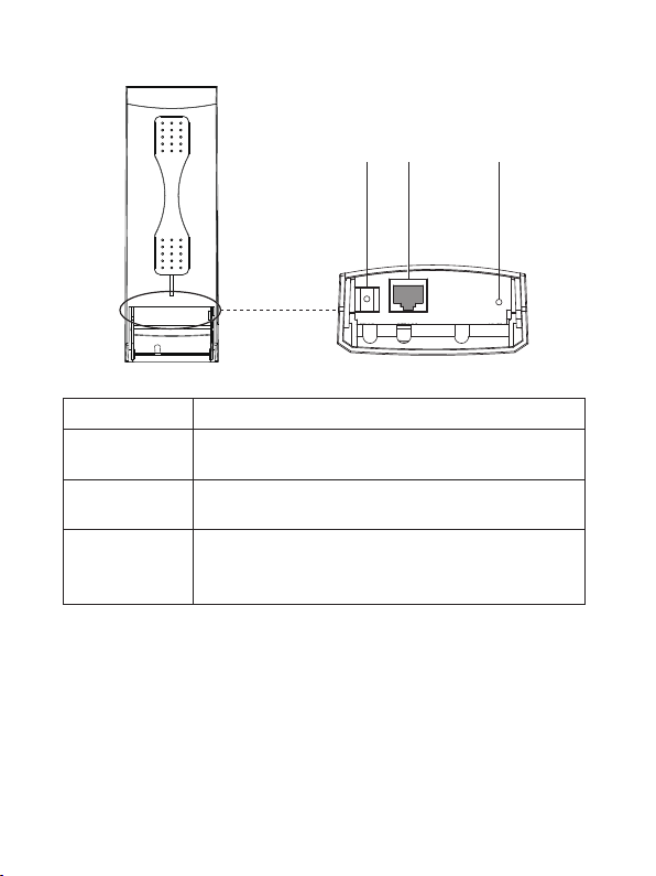
3. Ports and Buttons
RESETLAN1GND
(POE IN)
RESET
GND LAN1
(POE IN)
GND LAN(POE IN) RESET
03
Description
Press this RESET button for more than 5 seconds, the
device will restored to factory default settings and reboot
automatically.
This RJ45 Port is used to connect PoE box for both power
supply and data transfer.
This GND port is used to connect electrical ground for
ESD and lightning protection.
Ports and Buttons
GND
RESET
LAN(POE IN)
04
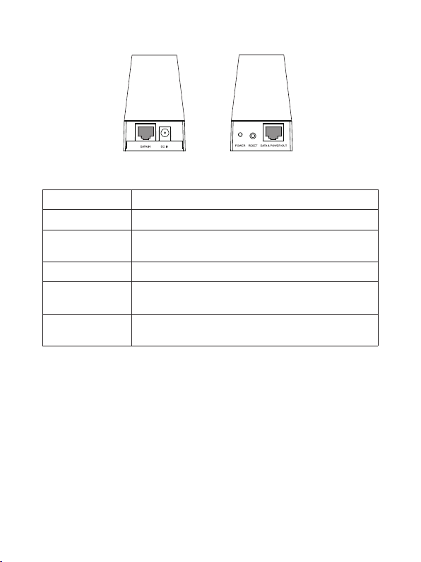
POE box POE box
front back
Description
Power indicator, it is lighting when power on
The DC IN socket is where you will connect the power
adapter.
Press the RESET button for more than 5 seconds,
TOTOLINK CPE will restore to factory default settings.
This RJ45 port is used to connect PC for data input
Ports and Buttons
DATA IN
POWER
DC IN
RESET
This RJ45 port is used to connect TOTOLINK CPE for
data and power transfer.
DATA & POWER
OUT
4. Passive PoE Box

05
Hardware Installation
1. Connection and Installation
① Insert a screwdriver into the seam between CPE shell and sliding closure;
② Press down the screwdriver to make the sliding closure slip off.
Step 1. Open the sliding closure on the CPE to plug into the Ethernet cable. This may
not easy because the sliding closure is fasten on in case it will come off when CPE
works outdoors. We recommend you refer to the operations on the below diagram
to make it easier.
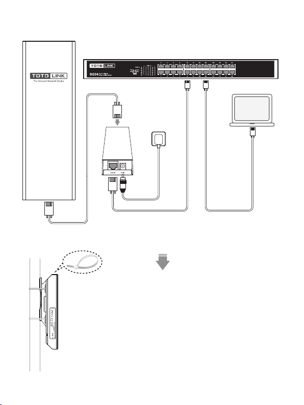
Step 2. After the Ethernet cable connection, push up the
sliding closure to make it fasten again on the case.
Step 3. Fix the CPE to the pole by strips, then adjust it to
face the Wi-Fi coverage area(see left-hand side).
POE box
Wall socket
Switch
24VPassive PoE
DefaultAccess:
Connection diagram:
Laptop
Router
06
07
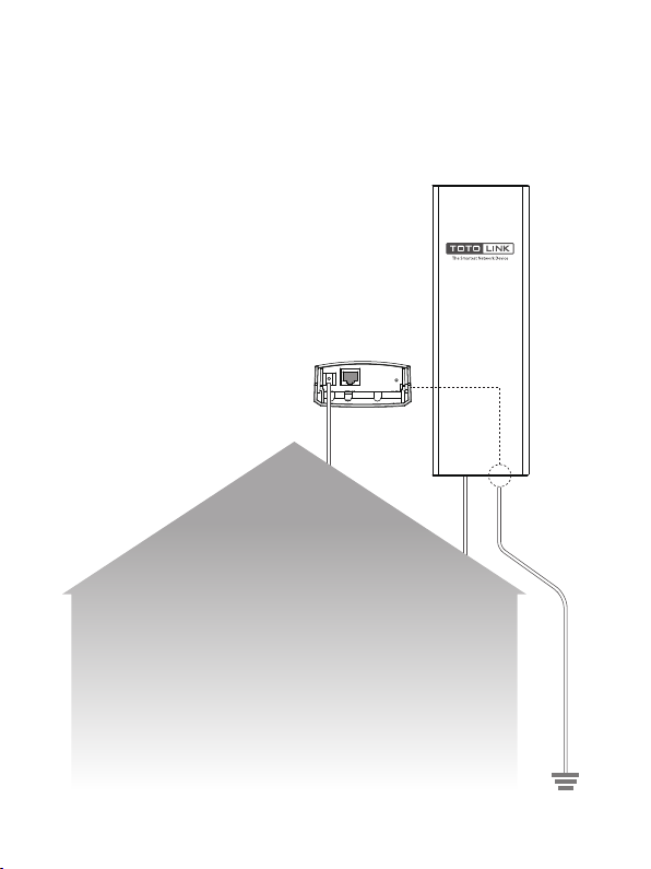
Grounding Method:
Ground wires
GND
Connect CPE’s GND to the earth by wires
2. ESD and lightning Protection
For outdoor devices, it is significant to do the grounding for lightning. If your wireless
CPE has a GND port, please connect the port to the earth terminal of the building by
yellow & green double color line for grounding, see below. Otherwise, we suggest you
use lightning protecon device for signal.
The earth
08
Easy Setup Guide
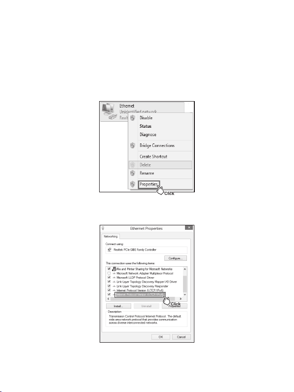
1. PC Settings(for Windows 8)
After hardware connection, please setup the network parameters of your PC.
1)Click “Start—Control Panel—Network and Sharing Center—Change adapter setting”,
right-click “Ethernet”, and choose “Properties”.
2)Double-click “Internet Protocol Version 4 (TCP/IPv4)”.

09
3)Choose “Use the following IP address”, input the IP address in the same
network segment with your router’s default IP address, as below, then click
“OK”.
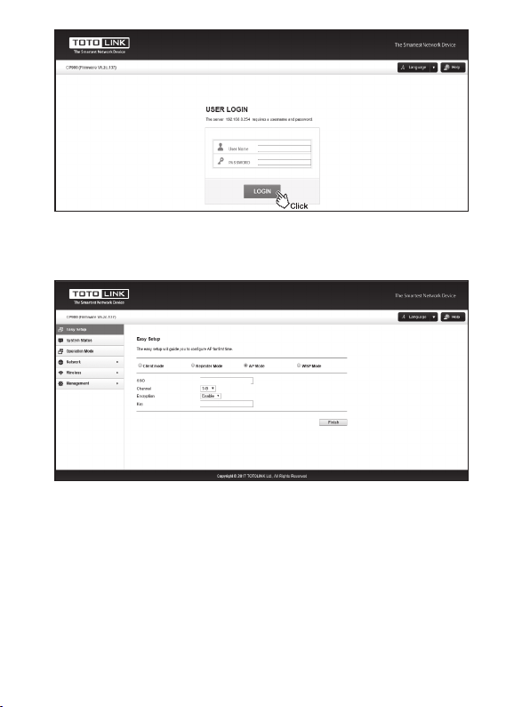
3)Upon initial login, enter admin in the User Name and Password �ields, and
select the appropriate Language from the Language drop-down lists. Then click
Login.
192 . 168 . 0 . 11
255 . 255 . 255 . 0
2. Web Interface Login
1)Open any Web browser.
2)Enter 192.168.0.254 to access the CPE.
192.168.0.254
10
3. Working Modes
1) AP Mode
admin
admin
4)Login to the Web interface successfully. First you will see the Easy Setup
page.
TOTOLINK CPE supports multiple working modes to satisfy diversi�ied
network requirement including AP Mode, Client Mode, Repeater Mode and WISP
Mode. The following guide introduces typical scenarios of each mode. You can choose
the scenario according to your needs.
TOTOLINK_5G_222222
totolink

11
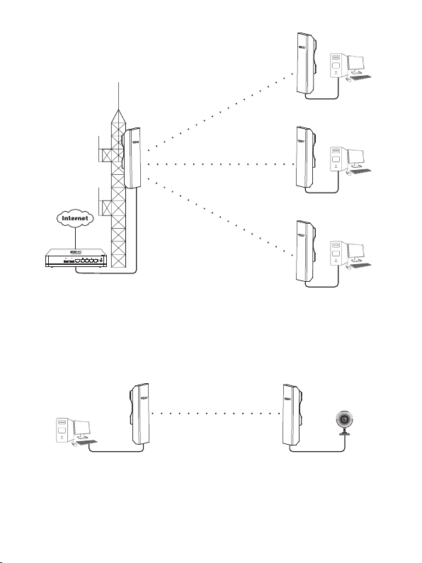
Scenario 1
Router
Switch
Switch Switch
Server
PC PC PC
24VPassive PoE
DefaultAccess:
Smart phone
Access Point
Campus network
Tablet
Laptop
12
Scenario 2
Scenario 3
Router
LAN: 192.168.7.1
Access Point
LAN: 192.168.7.2
WISP
LAN: 192.168.0.254
WAN: Dynamic IP
WISP
LAN: 192.168.0.254
WAN: PPPoE
WISP
LAN: 192.168.0.254
WAN: Static IP
Access Point
LAN: 192.168.0.254
Access Point
LAN: 192.168.0.2
PC IP Camera
13
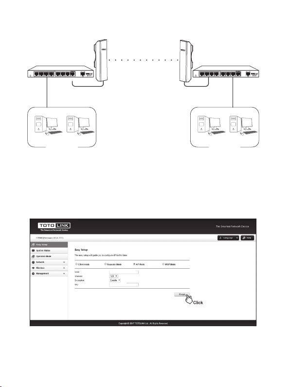
AP Settings
Connect two of�ice areas
1)Go to the CPE’s Easy Setup page.
Access Point
LAN: 192.168.0.254
Access Point
LAN: 192.168.0.2
Switch Switch
PC PC PC PC
Of�ice NetworkOf�ice Network
2)Choose “AP Mode”, setup the CPE’s SSID, Channel and Key(pass word), click
Finish.
3) After the settings, please connect the PoE box’s LAN port to upper level network
device.
TOTOLINK_5G_222222
totolink

14
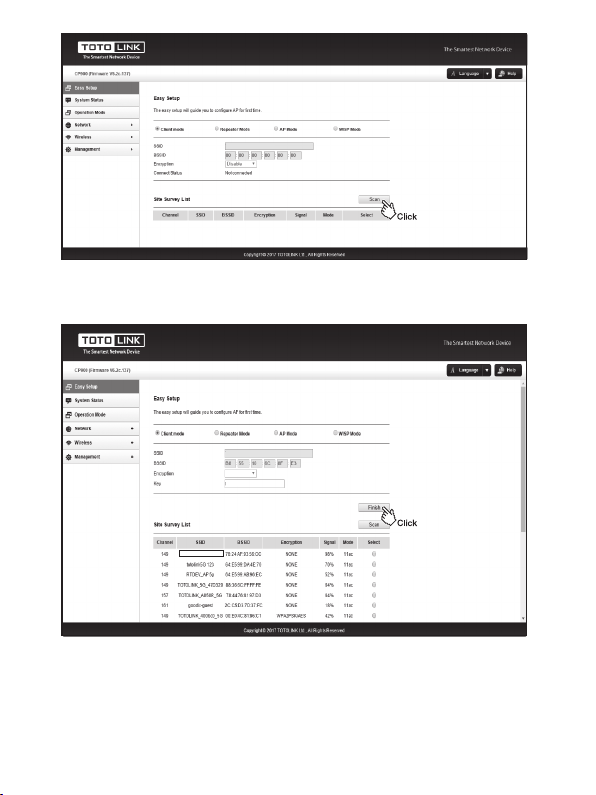
2) Client Mode
Client Settings
Scenario 1
1)Go to CPE’s Easy Setup page.
Connect two of�ice areas
Access Point
LAN: 192.168.0.254
Client
LAN: 192.168.0.2
Switch Switch
PC PC PC PC
Access Point
LAN: 192.168.0.254
Client
LAN: 192.168.0.2
PC IP Camera
Of�ice NetworkOf�ice Network
2)Choose “Client Mode”, clice “Scan”to check all available wireless networks
around.
15
3) Repeater Mode
3 ) Choose the SSID you need to connect. Enter correct key, click “Finish”.
TOTOLINK_RPT_5G
TOTOLINK_5G_6C8FE3
TOTOLINK_5G_6C8FE3
totolink
WPA2-PSK

16
Scenario 1
Scenario 2
Repeater Settings
1)Go to CPE’s Easy Setup page.
24VPassivePoE
DefaultAccess:
Router
LAN: 192.168.7.1
Access Point
LAN: 192.168.7.2
SSID: abc
Repeater
LAN: 192.168.7.3
SSID: abc
Repeater
LAN: 192.168.7.4
SSID: abc
智能手机
平板电脑
笔记本电脑
智能手机
平板电脑
笔记本电脑
智能手机
平板电脑
笔记本电脑
IP Camera
Repeater
LAN: 192.168.0.3
PC
Access Point
LAN: 192.168.0.254
Repeater
LAN: 192.168.0.2
SSID: abc SSID: abc
2)Choose “Repeater Mode”, click “Scan” to check all available wireless networks
around.

17
4 ) Setup the expanded network SSID and password. Click “Finish”.
TOTOLINK_5G_6C8FE3
totolink
WPA2-PSK
TOTOLINK_5G_6C8FE3
TOTOLINK RPT_5G
3)Select the SSID that you want to connect, enter correct key. Then click “Next” to
setup the expanded network parameters.
Table of contents
Other Toto Link Wireless Access Point manuals

Popular Wireless Access Point manuals by other brands


Ubiquiti
Ubiquiti NBE--2AC--13 quick start guide

Cisco MERAKI
Cisco MERAKI MR30H installation guide

Moxa Technologies
Moxa Technologies Airworks AWK-3131A-M12-RCC user manual

Solwise
Solwise WL-STATION-N5 user guide

Teletronics International
Teletronics International EZPlatform user manual

Silex technology
Silex technology AP-500AC user guide