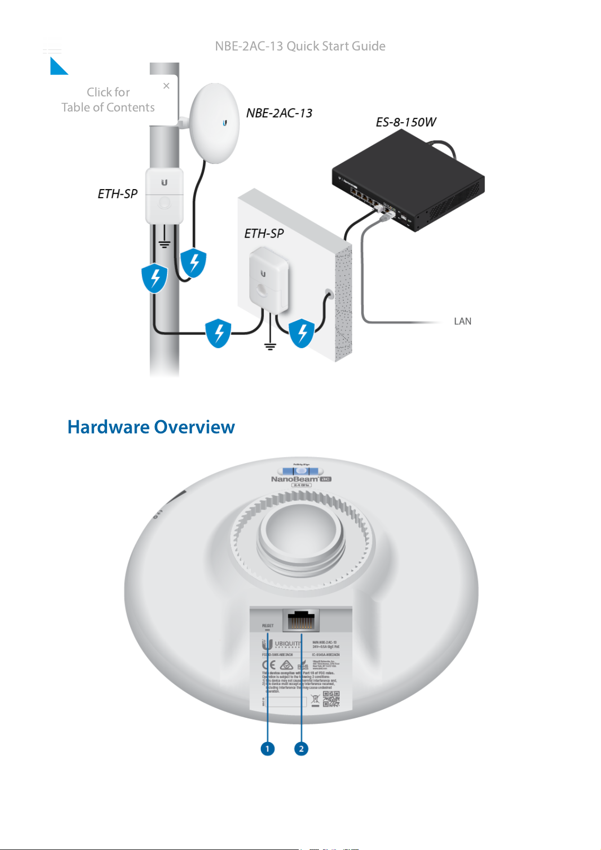
Ubiquiti NBE--2AC--13 User manual
Other Ubiquiti Wireless Access Point manuals

Ubiquiti
Ubiquiti RocketM Series User manual

Ubiquiti
Ubiquiti airFiber AF-11 User manual

Ubiquiti
Ubiquiti UniFi AC AP Mesh Pro User manual

Ubiquiti
Ubiquiti NanoBeam ac NBE-5AC-16 User manual

Ubiquiti
Ubiquiti LiteBeam LBE-5AC-LR User manual

Ubiquiti
Ubiquiti LiteBeam LBE5AC120-U User manual

Ubiquiti
Ubiquiti Rocket 5ac PtMP User manual

Ubiquiti
Ubiquiti PowerBeam AC GENZ User manual

Ubiquiti
Ubiquiti NanoBeam ac User manual

Ubiquiti
Ubiquiti Rocket R5AC-Lite User manual

Ubiquiti
Ubiquiti PBE-5AC-400-ISO-EU User manual

Ubiquiti
Ubiquiti UAP-PRO User manual

Ubiquiti
Ubiquiti UniFi AP AC Lite User manual

Ubiquiti
Ubiquiti UAP-PRO User manual

Ubiquiti
Ubiquiti Rocket M3 User manual

Ubiquiti
Ubiquiti AF-2X User manual

Ubiquiti
Ubiquiti UniFi UAP-AC-LR-5-EU User manual

Ubiquiti
Ubiquiti airFiber AF-11FX User manual

Ubiquiti
Ubiquiti UniFi UAP-FlexHD User manual

Ubiquiti
Ubiquiti UAP-AC-PRO-5 User manual


 installation guide")