manuals.online logo
Brands
  1. Home
  2. •
  3. Brands
  4. •
  5. Toto
  6. •
  7. Bathroom Fixture
  8. •
  9. Toto T114 User manual

Toto T114 User manual

T
O
T
O
-
d
e
s
i
g
n
a
t
e
d
Reinforcement
Installation manual
Required
03B19SN T1 2021.4
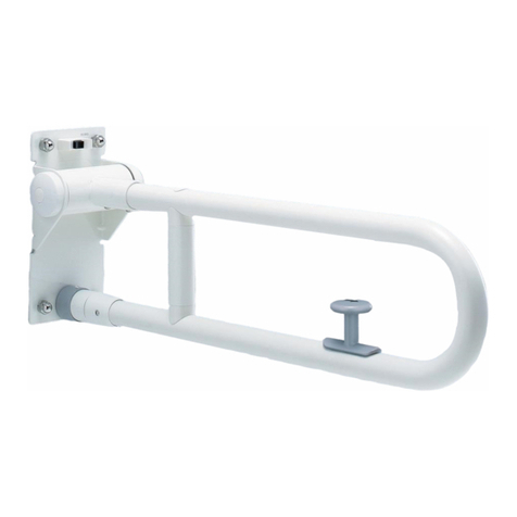
Handrail Combination Type
Follow the instructions in this installation manual to fully fulll the functions of this product. After installation, give full explanation on how to use this product to the customer.
1. Safety Precautions (
Be sure to observe these instructions.
)
Please read these “Safety Precautions” before installation, and install the product correctly.
WARNING
●This instruction manual shows various symbols to
correctly install the product in order to prevent harm to
customers and other users, and damage to property.
The meanings of those symbols are as follows:
●
The following symbols are used to classify
and explain instruction that must be followed.
WARNING
Prohibit
Do not
disassemble
Required
WARNING
T114 Type
2-1.Before Installation
1
Precautions before installation
When this appears next a topic,
this indicates that ignoring this
symbol and mishandling the
product could result in death or
serious injury.
No
backlash!
The symbol indicates
something that is “Prohibited.”
The symbol on the left indicates
“Do not disassemble.”
The symbol indicates
something that“Must be
implemented.” The symbol on
the left indicates “Required.”
Do not install the product outdoor or in areas that
might be submerged.
Doing so could cause a user to fall due to the damage or coming-off
of the handrail and may result in injury.
Anyone other than service engineers must not
disassemble, repair, or modify the product.
Failure to observe this warning could cause a user to fall due to the
damage or coming-off of the handrail and may result in injury.
When the product is used in wet areas such as a bathroom,
be sure to apply sealant around the mounting holes.
If sealant is not applied, water may enter the back of the wall and
cause the product to come off or the wall to collapse, which could
result in user’s fall and injury.
Be sure to install this product on a strong wall or building structure.
If the product is installed directly on a wall that is not strong enough,
including a soil wall and a gypsum board wall, it may come off or the
wall may collapse, which could result in user’s fall and injury.
Be sure to use TOTO-designated xing brackets.
If TOTO-designated xing brackets are not used, the handrail may
come off or the wall may collapse, which could result in user’s fall
and injury.
Make sure that the handrail has no backlash after the
installation is complete.
If the handrail has backlash, the handrail may come off or the wall
may collapse, which could result in user’s fall and injury.
Check the space between the handrail for Japanese-style toilet and its
surrounding xed objects and the installation position of the handrail.
Failure to do so could cause a part of the body (neck, etc.) to get caught
between the handrail and the xed object and may result in injury.
Make sure that the base has sufcient thickness and is reinforced,
and install the handrail by the specied installation method.
If the base does not have sufcient thickness or is not reinforced, and if you do
not follow the specied installation method for each base, the handrail may
come off or the wall may collapse, which could result in user’s fall and injury.
●Make sure that the wall where the handrail is attached is strong enough.
●When installing the handrail in combination with a product with a photoelectric sensor,
make sure that the sensor does not detect the handrail .
For the mounting positions of a product with photoelectric sensor and the handrail, see the manuals or
catalogs for products with photoelectric sensor.
●Select an appropriate mounting method depending on the structure of the building .
As the part number of the handrail and those of the wall- (oor-) xing brackets are different, please place an
order for the xing brackets separately depending on the wall structure.
See “ Fixing Brackets (Optional Parts)” for the required number of xing bracket sets.
*For installation methods not shown in this manual, contact TOTO’s branch ofce, branch shop, or sales ofce.
●See the catalogue, etc. for the handrail installation position. 
3.
<Remedial method>
Grip bar
(resin coated area)
●If the grip bar gets scratched on its resin-coated surface ( area shown in
“ Completion Drawing”), it cannot be repaired. Therefore, please handle the
product with care.
●As the resin-coated surface of the grip bar is made of soft resin, if a tool or the
like hits the grip bar, the surface of the grip bar may get dented. In that case,
remedy it by the following procedure.
4.
M6×150
2-2.
Before Installation
About the resin coating type grip bar
2
Note
T110D43
Clamping set Fixing position: 1 position
・
Continuous-thread stud: 4 pieces
・Washer: 8 pieces
・Nut: 12 pieces
<Fixing bracket list>
T110D37
T110D22R
T110D15(L=70)
T110D16(L=50)
T110D23(L=33)
t=3.2
φ4×16
250
150
Mounting bracket
for light-gauge steel
frame
Fixing position: 1 position
・
Mounting bracket: 1 piece
・
Drilling screw: 10 pieces
T110D36 φ4×16
t=3.2
250
150
340
150
Mounting bracket
for light-gauge steel
frame
Fixing position: 2 positions
(top and bottom)
・
Mounting bracket: 1 piece
・Drilling screw: 10 pieces
T110D44
M6×50Bolt set
(for light-gauge steel
frame)
Fixing position: 1 position
・Bolt: 4 pieces
・Washer: 4 pieces
T110D45
φ5×45Drilling screw set
(for light-gauge steel
frame)
Fixing position: 1 position
・Drilling screw: 4 pieces
・Washer: 4 pieces
T110D46
M6×50
M6
Mechanical nut set
(for light-gauge steel
frame)
Fixing position: 1 position
・
Mechanical nut: 4 pieces
・Bolt: 4 pieces
・Washer: 4 pieces
T110D26
<Fixing bracket list>
Anchor bolt Fixing position: 1 position
・Anchor bolt: 4 pieces
L
M6
T110D3R
(L=85)
T110D18R
(L=105)
Coach screw Fixing position: 1 position
・Coach screw: 4 pieces
・Washer: 4 pieces
L
φ6
Resin plug
Fixing position: 5 positions
・Resin plug: 20 pieces
φ8×40
Clamping bracket
(40 mm-thick, for
additional installation
to a toilet booth)
Fixing position: 1 position
・Mounting plate: 1 piece
・Bolt: 4 pieces
・Washer, nut, and resin
pipe: 4 pieces each
Fixing with hanger
bolts
Fixing position: 1 position
・Hanger bolt: 4 pieces
・Washer and nut:
4 pieces each
M6×11
φ6×L
Hanger
bolt
T110D34
(L=50)
T110D35
(L=30)
(Unit: mm)
ShapePart No. Details of the setName
<Fixing bracket list> (Unit: mm)
ShapePart No. Details of the set
T110D41
T110D38
T110D63
T110D42
Mounting plate Fixing position: 1 position
・Mounting plate: 1 piece
φ8
M6
100×100×t6
Welding set Fixing position: 1 position
・
Continuous-thread stud: 4 pieces
・Washer: 4 pieces
・Nut: 8 pieces
M6×60
Embedding set Fixing position: 1 position
・
Continuous-thread stud: 4 pieces
・
Washer: 4 pieces,
・
Nut: 8 pieces
・Anchor bolt: 4 pieces
M6×60 M6×50
Name
Mounting plate Fixing position: 2 positions
(top and bottom)
・Mounting plate: 1 piece
260
150
φ8
M6
t6 100
3-1. Fixing Brackets (Optional Parts)
Use the inner
bolt holes
M6×55
Resin
pipe
φ13
Apply hot air to the dented portion with a hair dryer for about 2
or 3 minutes.
*
The time to apply hot air varies depending on the degree of the dent.
Remedy it while checking its recovering condition.
Note
Do not apply hot air to the soft resin on the surface of
the grip bar too long. Doing so may cause the soft
resin portion to burn or change in color.
3
<List of the required numbers of xing brackets and those of parts to be procured in the eld>
*●shows the parts that need to be procured in the eld. “Pipe” indicates metal pipes (φ13.8,
t2). Please purchase them at a hardware store or a home improvement center. Prepare pipes
with an appropriate length considering the thickness of the wall.
* "-" means that it cannot be installed.
Note 1: [GL method] Available only when the thickness of GL (Gypsum Lining) is 50 mm or less.
Note 2: [Concrete block base] Available only when the thickness from the back of the concrete
block to the nished wall surface is 125 mm or less.
Note 3: For the thickness of reinforcing wooden blocks, see " (P. 10) ."
Note 4: The toilet booths for which the xing brackets are available are those made from paper
honeycomb, melanin, or polyether decorative plywood, or the equivalent, which is 40
mm in thickness.
Note 5: Available only for toilet booths with a wall thickness of 30 mm or more.
Note 6: Please place an order for T110D26 (resin plug: 20 pieces) depending on the required
number of screws. The required number of screws is 8 for I type and 12 for L type.
Note 7: Use hanger bolts for the intermediate support part, which facilitate installation. If coach
screws are used, a screwdriver could interfere with the cover, making it difcult to install
the product, and it may cause damage to the cover.
Note 8: If the thickness of the nished wall surface is 15 mm or less, T110D23 can also be used.
Note 9: If the thickness of the nished wall surface is 15 mm or less, T110D35 can also be used.
Note 10: Use bolts for the intermediate support part. If drilling screws are used, a screwdriver
could interfere with the cover, making it difcult to install the product, and it may cause
damage to the cover.
Note 11: Floor-xing brackets shown in the list are for installation by xing with anchor bolts
(concrete oor). When the oor is a wooden base, change the oor-xing type
T110D3R (xing with anchor bolts) to T110D15 (xing with coach screws). In the case
of a wooden base, reinforcement of 60 mm or more is required.
Note
7-3.
T110D63×1,T110D43×2
T110D3R×1
Versatile I type handrail
Versatile L type handrail (T114CL9)
L type handrail for sitting toilet (T114CL10)
L type handrail for sitting toilet (T114CL11/CL12)
P type handrail for sitting toilet (T114CP21/CP22)
Note 11
Handrail for urinal (T114CU22)
Handrail for wall-mounted washbasin (T114CP23)
Note 11
Product name
Base (mounting method)
T110D38×2,T110D42×2
T110D38×3,T110D42×3
T110D38×3,T110D42×3
T110D38×3,T110D42×3
T110D63×2,T110D42×4
Concrete base, GL (Gypsum Lining) method
(Fixing by embedding a mounting plate)
Note 1
T110D63×1,T110D42×2
T110D3R×1
T110D63×1,T110D42×2
T110D3R×1
T110D3R×2
T110D3R×3
T110D3R×3
T110D3R×3
T110D3R×3
T110D3R×4
T110D3R×3
Concrete base
(Fixing with anchor bolts)
T110D16 × 2, T110D26Note 6
T110D16 × 2, T110D34 × 1Note 7
T110D26Note 6
T110D16 × 2, T110D34 × 1Note 7
T110D26Note 6
Concrete base/
Concrete block base
(Fixing with plugs)
T110D63×1,T110D43×2
T110D3R×1
T110D38×2,T110D43×2
T110D38×3,T110D43×3
T110D38×3,T110D43×3
T110D38×3,T110D43×3
T110D63×2,T110D43×4
Wooden base/Concrete block base
(Fixing by clamping a mounting plate)Note 2
T110D16 × 2Note 8
T110D16 × 2Note 8
T110D34 × 1Notes 7 and 9
T110D16 × 2Note 8
T110D34 × 1Notes 7 and 9
T110D15×3
T110D15×2,T110D3R×1
T110D15×4
T110D15×2,T110D3R×1
Wooden base
(Fixing with coach screws)
Note 3
3-2. Fixing Brackets (Optional Parts)
1
2
3
4
7
6
5
8
T110D18R × 2, ●Pipe × 8
T110D18R × 3, ●Pipe × 12
T110D18R × 2, T110D3R×1
●Pipe × 8
T110D18R × 4, ●Pipe × 16
T110D18R × 2, T110D3R×1
●Pipe × 8
GL method
(Fixing with anchor bolts + pipes)
Note 1
T110D22R×2
T110D22R×3
T110D22R×3
Light-gauge steel base
(Fixing with bolts)
T110D37×2,T110D44×2
T110D37×3,T110D44×3
T110D37×3,T110D44×3
T110D37×3,T110D44×3
T110D36×2,T110D44×4
T110D36×1,T110D44×2
T110D3R×1
T110D36×1,T110D44×2
T110D3R×1
Light-gauge steel base
(Fixing with drilling screws)
T110D37×2,T110D45×2
T110D37×3,T110D45×2
T110D44 × 1
Note 10
T110D37×3,T110D45×3
T110D44 × 1
Note 10
T110D37×3,T110D45×3
T110D36×1,T110D45×2
T110D3R×1
T110D36×2,T110D45×4
T110D36×1,T110D45×2
T110D3R×1
Light-gauge steel base
(Fixing with mechanical nuts)
T110D37×2,T110D46×2
T110D37×3,T110D46×3
T110D37×3,T110D46×3
T110D37×3,T110D46×3
T110D36×1,T110D46×2
T110D3R×1
T110D36×2,T110D46×4
T110D36×1,T110D46×2
T110D3R×1
Light-gauge steel base
(Fixing by welding a mounting plate)
T110D38×2,T110D41×2
T110D38×3,T110D41×3
T110D38×3,T110D41×3
T110D38×3,T110D41×3
T110D63×1,T110D41×2
T110D3R×1
T110D63×2,T110D41×4
T110D63×1,T110D41×2
T110D3R×1
T110D23×2
T110D23×2
T110D35 × 1
Note 7
T110D23×2
T110D35 × 1
Note 7
3-3. Fixing Brackets (Optional Parts)
4
1
2
3
4
7
6
5
8
Toilet booth
(Fixing by clamping)
Note 4
Toilet booth
(Fixing with coach screws)
Note 5
φ73
φ73
φ34
Wall surface
Floor surface
L
150550
700
250
A
φ73
320
470
150
550
50
600
300
250
φ34
Wall surface
φ73
φ34
φ73
Wall surface
800
550250
150590
740
Floor surface
A
A
L
Wall surface
90
φ34
φ73
Wall surface
φ73
φ34
Intermediate
support part: φ27
700
18
700
18 90 18
700
18
Wall surface
φ73
φ34
Intermediate
support part: φ27
700 120
18
L
18
Wall surface
φ73
φ34
Intermediate
support part: φ27
L 230
* areas shown in the drawings indicate resin-coated areas.
Versatile L type handrail L type handrail for sitting toiletVersatile I type handrail
P type handrail for sitting toilet Handrail for wall-mounted washbasinHandrail for urinal
(Unit: mm)
4. Completion Drawing
5
Part No. WeightL Part No.
T114CL9
Weight
2.5kg
Part No.
T114CL10
Weight
2.6kg
Part No.L
700
800
T114CL12
T114CL11
Weight
3.1kg
3.4kg
Part No.
T114CU22
Weight
6.2kg
Part No.
T114CP23
Weight
3.9kg
Part No.L
550
700
T114CP21
T114CP22
Weight
3.1kg
3.5kg
600
T114C6
T114C8
1.2kg
1.5kg
800
Concrete base
Fixing with anchor bolts
See P. 8.
Fixing with plugs
See P. 9.
See P. 8.
Fixing with coach screws and hanger bolts
Fixing by clamping
Toilet booth
See P. 10.
See P. 14.
Concrete block base
Fixing with plugs
See P. 9.
Fixing by clamping a mounting plate
See P. 11.
Wooden base
Fixing with coach screws and hanger bolts
Fixing by clamping a mounting plate
See P. 10.
See P. 11.
Fixing by embedding a mounting plate
GL method
See P. 8.
Fixing with anchor bolts + pipes
See P. 12.
●Temporarily tighten T114CP21, CP22, CP23, and T114CU22, to the specied shape, assemble the product, and then fully tighten again.
●Make sure that the screws and bolts to be used to assemble the handrail are in the packing box. (Only for handrails to be assembled)
 *Fixing brackets for installing the handrail on the wall (oor) are optional parts.
Check the connection method of the connection part.
When using bolts
See P. 7.
See P. 15.
See P. 15.
When there is no connection
part in the completion drawing
Fixing by welding a mounting plate
Light-gauge steel base
Fixing with drilling screws
Fixing with bolts
Fixing with mechanical nuts
See P. 12.
See P. 13.
See P. 13.
See P. 13.
4.
When the connection part in the
completion drawing is A
4.
Assembling the Handrail
6.
Mounting the handrail
7.
Finishing the Connection Part
8.
Inspection Items
9.
5. Installation Work Flow
6
Fixing by embedding a mounting plate
See P. 8.
Note
7
Grip bar
Grip bar
Bolt
Spring washer
Do not fully tighten the bolts
before mounting the handrail.
If the handrail is mounted after
fully tightening the bolts, you may
fail to install the handrail.
[ In the case of in Completion Drawing]
4. A
6. Assembling the Handrail
When using bolts
Put the bolt through the spring washer according
to the order shown in the gure on the right, and
then temporarily fasten the grip bars to each
other with a hexagonal wrench.
Notes
①Carry out centering and then make
prepared holes of φ6 mm and 85 mm
or more in depth for anchor bolts.
②Screw the nuts about 2 mm from the
upper ends of the anchor bolts, and
then drive them in the prepared holes
lightly.
③Tighten the nuts on the anchor bolt.
(This opens the wedges of the anchor
bolts and prevents the anchor bolts
from coming out.)
④Remove the nuts from the anchor
bolts.
⑤Adjust the projecting length of the
anchor bolts to be between 9 and 12
mm from the nished wall surface.
⑥Put the anchor bolts through the
mounting holes of the ange, and
then tighten with the nuts.
⑦Press the cover against the nished
surface.
Note 1
Note 2
Note 3
Anchor bolt
Cover
Flange
Finished
wall surface
Concrete
37 or more
85 or more
9 to 12
Prepared
hole (φ6)
Nut
Mortar
(Unit: mm)
Finished wall surface Finished wall surface
Notes
Concrete
50 or more
37 or more
Anchor bolt
Mortar
Nut
Nut
Mounting plate
Washer Washer
Cover
Flange
9 to 12
Anchor bolt
Fill mortar
37 or more
Prepared hole
(φ6) Prepared hole
(φ6)
Concrete
Gypsum board
50 or more
GL bond
<Concrete base> <GL method>
Nut
Nut
Mounting plate
Cover
Flange
9 to 12
50 or less
Continuous-thread
stud
Continuous-thread
stud
①Carry out centering and then make prepared holes of φ6 mm and 50 mm or more in depth for anchor bolts.
②Screw the nuts about 2 mm from the upper ends of the anchor bolts, put the bolts through the mounting hole
of the mounting plate, and then drive them in the prepared holes lightly.
③Tighten the nuts on the anchor bolt.
④Screw continuous-thread studs into the bolt holes of the mounting plate and tighten them with nuts.
⑤After nishing the wall, adjust the projecting length of the continuous-thread studs to be between 9 and 12
mm from the nished wall surface.
⑥Put the continuous-thread studs through the mounting holes of the ange, and then tighten with the washers
and nuts.
⑦Press the cover against the nished surface.
Note 2
Notes 3 and 4
Note 4
Note 1
(Unit: mm)
7-1. Installing the Handrail
8
Concrete base: Fixing with anchor bolts
Concrete base, GL method: Fixing by embedding a mounting plate
Fixing bracket part number T110D3R Fixing bracket part number T110D38,T110D63,T110D42
Note 1: Use a drill that can make prepared holes of φ6 mm and
85 mm or more in depth in concrete. If the bit size of the
drill is too large or if it has core deviation, you may fail to
x it securely.
Note 2: The embedding length of the anchor bolts in concrete
must be 37 mm or more.
Note 3: Adjust the projecting length of the anchor bolts to be
between 9 and 12 mm from the nished wall surface.
Note 1: Use a drill that can make prepared holes of φ6 mm and 50 mm or more in depth in
concrete.
If the bit size of the drill is too large or if it has core deviation, you may not be able to
secure the mounting plate securely.
Note 2: The embedding length of the anchor bolts in concrete must be 37 mm or more.
Note 3: Adjust the projecting length of the bolts to be between 9 and 12 mm from the nished
wall surface.
Note 4: If the bolts are not long enough, procure M6 continuous-thread studs in the eld.
120 or less
60 or more
9 to 12
Prepared hole
(φ8)
Resin plug
Hanger bolt
Hanger bolt
Nut
Washer
Finished wall surface
120 or less
120 or less 9 to 12
Cover Cover
Finished wall surface
60 or more
120 or less
Flange
Washer
Prepared hole
(φ8)
Prepared hole
(φ8)
Resin plug
Coach screw
Cover
Resin plug
Coach screw
Mortar
Mortar
Concrete
Mortar
Concrete
Flange
Washer 60 or more
Concrete block
Concrete block
Finished wall surface
Prepared hole
(φ8)
Cover
Resin plug
Mortar
Washer 60 or more
Nut
Flange
Flange
Notes
Note
Coach screw
Hanger bolt
Intermediate
support part
Screw 2 nuts and turn the nuts to the different directions each other
to tighten and x.
①Carry out centering and then make prepared holes
of φ8 mm and 60 mm or more in depth for resin
plugs.
②Lightly drive the resin plugs into the prepared
holes.
③Fix using the nuts (2 pieces) as a double nut,
which come with the hanger bolts.
④Turn the double nut xed in ③using a tool, and screw the hanger bolt into the resin plug in the
intermediate support part of the handrail.
⑤Adjust the projecting length of the bolts to be between 9 and 12 mm from the nished wall
surface.
⑥Remove the double nuts.
⑦Put the hanger bolt through the mounting hole of the ange in the intermediate support part of
the handrail, and then temporarily tighten with the washer and nut.
⑧Put the coach screws through the washers and attach to the wall through the mounting hole of
the ange.
⑨Fully tighten the nut that is temporarily tightening the hanger bolt.
⑩Press the cover against the nished surface.
Note 1
Note 2
<Concrete base>
<Concrete block base>
・When xing with coach screws ・When xing with hanger bolts
(Unit: mm)
7-2. Installing the Handrail
9
Concrete base/Concrete block base: Fixing with plugs
Fixing bracket part number T110D16,T110D26,T110D34
Only versatile I type handrail, versatile L type handrail, and L type handrail for
sitting toilet (front protrusion dimension: 120 mm) can be installed.
For the intermediate support parts of the versatile L
type handrail and the L type handrail for sitting toilet
(front protrusion dimension: 120 mm), use hanger
bolts that facilitate installation.
As the versatile I type handrail does not use hanger
bolts, its installation procedure is ①, ②, ⑧, and ⑩.
Note 1: Use a drill that can make prepared holes of φ8 mm and 60 mm or more
in depth in concrete. If the bit size of the drill is too large or if it has
core deviation, you may fail to x it securely.
Note 2: Adjust the projecting length of the hanger bolts to be between 9 and 12
mm from the nished wall surface.
Flange
Prepared hole (φ4)
for coach screw
Prepared hole (φ4)
for coach screw
Plywood,
etc.
Cover
Washer
120 or less
Cover
Cover
Washer
Reinforcing
wooden block
Paper honeycomb Decorative
plywood
sheet
30 or more
Prepared hole
(φ4) for hanger
bolt
Prepared hole (φ4)
for hanger bolt
Reinforcing
wooden block
30 or more
Paper honeycomb
Decorative
plywood sheet
Nut
Washer
Nut
<Wooden base> <Toilet booth>
9 to 12
9 to 12
120 or less
Plywood, etc.
Prepared hole (φ4)
for coach screw
Washer
Flange
Flange
Flange
Reinforcing
wooden
block
Plywood, etc.
Cover
Cover
Washer
Prepared hole
(φ4) for hanger bolt
Reinforcing
wooden
block
Cover
Washer
Nut
9 to 12
Plywood, etc.
Finished wall surface
Finished wall surface Finished wall surface Finished wall surface
Finished wall surface
(Unit: mm)
Flange
Flange
Screw 2 nuts and turn the nuts to the different
directions each other to tighten and x.
Coach screw
Hanger bolt
Intermediate
support part
①Mount reinforcing wooden blocks on the
handrail mounting area beforehand.
②Carry out centering and then make prepared
holes of φ4 mm for hanger bolts.
(In the case of a tile wall, make through holes
of φ6.5 mm only in the tile area.)
③Fix using the nuts (2 pieces) as a double nut,
which come with the hanger bolts.
Note 1
④Turn the double nut xed in ③using a tool, and screw the hanger bolt into the prepared hole
in the intermediate support part of the handrail.
⑤Adjust the projecting length of the bolts to be between 9 and 12 mm from the nished wall
surface.
⑥Remove the double nuts.
⑦Put the hanger bolt through the mounting hole of the ange in the intermediate support part
of the handrail, and then temporarily tighten with the washer and nut.
⑧Put the coach screws through the washers and attach to the wall through the mounting hole
of the ange.
⑨Fully tighten the nut that is temporarily tightening the hanger bolt.
⑩Press the cover against the nished surface.
Note 2
Notes
Target product Thickness of plywood sheet
or reinforcing wooden block
30 mm or more
60 mm or more
・Versatile handrail I type
・Versatile handrail L type
・Handrail for sitting toilet L type
(T114CL11・CL12)
・Handrail for sitting toilet P type
・Handrail for Japanese-style toilet
・Handrail for urinal
・
Handrail for wall-mounted washbasin
12 mm or more
・
Handrail for sitting toilet L type
(T114CL10)
10
Wooden base, Toilet booth: Fixing with coach screws and a hanger bolt
Fixing bracket part number Wooden base: T110D15, T110D16, T110D34
Toilet booth: T110D23, T110D35
7-3. Installing the Handrail
For the intermediate support parts of the versatile L type handrail and the L type handrail for
sitting toilet (front protrusion dimension: 120 mm), use hanger bolts that facilitate installation.
As the versatile I type handrail does not use hanger bolts, its installation procedure is ①, ②, ⑧,
and ⑩.
Note 1: The thickness of the reinforcing wooden blocks differs depending on the
type of handrail. Give reinforcement appropriate for the handrail.
Mount a reinforcing plywood sheet or wooden blocks with a thickness that conforms
to the table below securely on a strong pillar, etc. If reinforcing wooden blocks are
not mounted, the handrail may have backlash or come off.
Note 2: Adjust the projecting length of the hanger bolts to be between 9 and 12 mm
from the nished wall surface.
*Only when the front protrusion dimension
of the handrail is 120 mm or less.
*Mount a structural plywood sheet (JAS
standard product) or an equivalent or
better one to the base material.
Notes Notes
Finished wall
surface
9 to 12
125 or less
Concrete block
Mortar
Mounting plate
Cover
Flange
Through hole
(φ8)
Washer
Nut
Continuous-
thread stud
①Carry out centering and then make
through holes of φ8 mm for
continuous-thread studs.
②Screw the continuous-thread studs into
the bolt holes of the mounting plate
and tighten them with nuts.
③Insert the continuous-thread studs into
the through holes, put the mounting
plate on the back of the wall, and
tighten with the washers and nuts from
the handrail mounting side.
④After nishing the wall, adjust the
projecting length of the
continuous-thread studs to be between
9 and 12 mm from the nished wall
surface.
⑤Put the continuous-thread studs
through the mounting holes of the
ange, and then tighten with the
washers and nuts. 
⑥Press the cover against the nished
surface.
Note 3
Plywood, etc.
Reinforcing
wooden block
Cover
Flange
Finished wall
surface
Nut
Mounting
plate
Through hole
(φ8)
Continuous-
thread stud
45 to 60
9 to 12
Washer
①Mount reinforcing wooden blocks of 45 to 60 mm
in thickness on the handrail mounting area
beforehand.
②Carry out centering and then make φ8-mm
through holes for continuous-thread studs.
③Screw the continuous-thread studs into the bolt
holes of the mounting plate and tighten them
with nuts.
④Insert the continuous-thread studs into the
through holes, put the mounting plate on the
back of the wall, and tighten with washers and
nuts from the handrail mounting side.
⑤After nishing the wall, adjust the projecting
length of the continuous-thread studs to be
between 9 and 12 mm from the nished wall
surface.
⑥Put the continuous-thread studs through the
mounting holes of the ange, and then tighten
with the washers and nuts.
⑦Press the cover against the nished surface.
Note 3
(Unit: mm) (Unit: mm)
11
Wooden base: Fixing by clamping a mounting plate
Concrete block base: Fixing by clamping a mounting plate
7-4. Installing the Handrail
Fixing bracket part number T110D38,T110D63,T110D43 Fixing bracket part number T110D38,T110D63,T110D43
Note 1
Notes 2 and 4
Note 1: Mount reinforcing wooden blocks of 45 to 60 mm in thickness
securely on a strong pillar, etc.
Note 2: Adjust the projecting length of the continuous-thread studs to be
between 9 and 12 mm from the nished wall surface.
Note 3: Be careful not to overtighten the nuts to avoid tiles from breaking.
Note 4: If the bolts are not long enough, procure M6 continuous-thread studs
in the eld.
Note 1: It is not necessary to ll hollows with mortar, etc.
Note 2: Adjust the projecting length of the continuous-thread studs to be
between 9 and 12 mm from the nished wall surface.
Note 3: Be careful not to overtighten the nuts to avoid tiles from breaking.
Note 4: If the bolts are not long enough, procure M6 continuous-thread studs
in the eld.
Note 1
Notes 2 and 4
Notes
Notes
Finished wall surface
Nut
9 to 12
Flange
Cover
Light-gauge
steel frame
Plywood, etc.
Mounting plate
Continuous-thread
stud
Fixing by welding
t 2.3 or more
Through hole (φ8)
Washer
Reinforcing
material
(t 2.3 or more)
Stud
Mounting plate
①While carrying out centering, x the
mounting plate to the reinforcing
light-gauge steel frame (t 2.3 mm or
more) by welding.
②Screw the continuous-thread studs into
the holes of the mounting plate, adjust
their projecting length to be between 9
and 12 mm from the nished wall
surface, and tighten from the back of the
wall with nuts.
③Finish the wall.
④Put the continuous-thread studs through
the mounting holes of the ange, and
then tighten with the washers and nuts.
⑤Press the cover against the nished
surface.
*You cannot adjust the
mounting position of the
handrail after nishing the
wall.
Note 1
Note 2
Note 3
(Unit: mm)
12
T110D38,T110D63,T110D41
Fixing bracket part number
Part to be procured in the eld φ13.8 (t2) metal pipe
Fixing bracket part number T110D18R
Nut
Flange
Cover
Through hole (φ14)
Finished wall surface
Prepared
hole (φ6)
37 or more
105 or more
GL bond
Anchor bolt
50 or less
Gap
9 to 12
(0.5)
Concrete
Gypsum board
Metal pipe
・White characters in indicate parts to be
procured in the eld.
Washer
(Unit: mm)
7-5. Installing the Handrail
GL method: Fixing with anchor bolts + pipes
Light-gauge steel base: Fixing a mounting plate by welding
①Carry out centering and then make
prepared holes for anchor bolts, which
are φ6 mm and 105 mm or more in
depth from the nished wall surface.
②Make through holes of φ14 mm for metal
pipes only in the gypsum board part.
③Insert the metal pipes until they hit the
concrete base surface, and cut it in such
a way that it protrudes about 0.5 mm
from the nished wall surface.
*If the length is not enough, insert a
washer to adjust the length.
④Screw the nuts about 2 mm from the
upper ends of the anchor bolts, put the
bolts through the metal pipes, and then
drive them in the prepared holes lightly.
⑤Tighten the nuts on the anchor bolt. (This
opens the wedges of the anchor bolts
and prevents the anchor bolts from
coming out.)
⑥Remove the nuts from the anchor bolts.
⑦Adjust the projecting length of the anchor
bolts to be between 9 and 12 mm from
the nished wall surface.
⑧Put the anchor bolts through the
mounting holes of the ange, and then
tighten with the washers and nuts.
⑨Press the cover against the nished surface.
Note 1
Note 2
Note 3
Note 1: Use a drill that can make prepared holes of φ6 mm and 105 mm or
more in depth in concrete. If the bit size of the drill is too large or if it
has core deviation, you may fail to x it securely.
Note 2: The embedding length of the anchor bolts in concrete must be 37 mm
or more.
Note 3: Adjust the projecting length of the anchor bolts to be between 9 and
12 mm from the nished wall surface.
Note 1: Use reinforcing light-gauge steel frames of t 2.3 mm or more.
Note 2: Adjust the projecting length of the continuous-thread studs to be
between 9 and 12 mm from the nished wall surface.
Note 3: Be careful not to overtighten the nuts to avoid tiles from breaking.
13
Notes
(Unit: mm) (Unit: mm)
(Unit: mm)
Fixing bracket part number T110D36,T110D37,T110D45
Fixing bracket part number T110D36,T110D37,T110D46
Fixing bracket part number T110D36,T110D37,T110D44
Reinforcing
material
(t 2.3 or more)
Stud
Mounting bracket
①In the handrail mounting position, x the
mounting bracket for light-gauge steel
frames to the reinforcing light-gauge steel
frames (t 2.3 mm or more) with drilling
screws.
②After nishing the wall, carry out handrail
centering and make prepared holes of φ3
to 3.5 mm with a drill. 
③Make about φ8-mm through holes for
drilling screws in the nished wall area.
④Put the drilling screws through the washers
and attach to the wall through the mounting
hole of the ange.
⑤Press the cover against the nished surface.
①In the handrail mounting position, x the
mounting bracket for light-gauge steel
frames to the reinforcing light-gauge steel
frames (t 2.3 mm or more) with drilling
screws.
②After nishing the wall, carry out handrail
centering and make φ5.1-mm prepared
holes for M6 tapping.
 Make about φ8-mm through holes in the
nished wall area.
③Perform M6 tapping in the mounting bracket
for the light-gauge steel frames.
④Put the bolts through the washers and
attach to the wall through the mounting
holes of the ange.
⑤Press the cover against the nished surface.
*After nishing the wall, you can adjust the
handrail-mounting position within the range of
the mounting bracket.
①In the handrail mounting position, x the
mounting bracket for light-gauge steel
frames to the reinforcing light-gauge steel
frames (t 2.3 mm or more) with drilling
screws.
②After nishing the wall, carry out handrail
centering and make φ12-mm through holes
for mechanical nuts.
③Insert the mechanical nuts into the through
holes and set them.
④Put the bolts through the washers and
attach to the wall through the mounting
holes of the ange.
⑤Press the cover against the nished surface.
Note 1
Note 2
Note 3
Note 1
Note 3
Note 1
Note 3
Flange
Cover
Finished wall surface
Plywood, etc.
Mounting bracket
Drilling screw
Washer
Flange
Cover
Plywood, etc.
Mounting bracket
Through hole (φ12)
Bolt Mechanical nut
Washer
Flange
Cover
Finished wall surface Plywood,
etc.
Mounting bracket
Through hole
(φ8)
Through hole (φ8)
Prepared hole
(φ3 to φ3.5)
Bolt
Prepared
hole for M6
tapping
(φ5.1)
Washer
7-6. Installing the Handrail
Light-gauge steel base: Fixing with drilling screws Light-gauge steel base: Fixing with bolts
Light-gauge steel base: Fixing with mechanical nuts
Note 1: Use reinforcing light-gauge steel frames of t 2.3 mm or more.
Note 2: In order to prevent the handrail from being scratched, make prepared
holes to facilitate installation.
Note 3: Be careful not to overtighten the nuts to avoid tiles from breaking.
Note
Note
Prepared hole guide for xing bracket T110D22R
*Do not use the outer holes because they are the mounting hole
positions for the handrail (T112 type/T113 type).
Mounting hole positions (inner holes)
of the handrail (T114 type)
φ55
Mounting plate
39
39
14
Toilet booth: Fixing by clamping
Use the inner holes
40
Washer
Nut
Through hole
(φ13)
Bolt Decorative
plywood
sheet
Paper honeycomb
Mounting plate
Flange
Cover
Finished wall surface
Within 120
Resin pipe
When the toilet booth is made from paper honeycomb, melanin/polyether
decorative plywood, or the equivalent, which is 40 mm in thickness, only
versatile I type handrail, versatile L type handrail, and L type handrail for
sitting toilet (front protrusion dimension: 120 mm) can be installed.
*For installation methods not shown in this manual, please contact TOTO’s branch ofce, branch shop, or sales ofce.
①Carry out centering and then make φ13-mm
through holes for pipes.
②Insert the resin pipes into the through holes.
Resin pipes are used to prevent wall buckling
which occurs when the handrail is installed on
a paper honeycomb wall or the like. Therefore,
be sure to check the wall before installing the
handrail.
③Screw the continuous-thread studs into the
inner bolt holes of the mounting plate to the
end, and while inserting them into the resin
pipes from the back of the booth, put the
mounting plate on the wall.
*The mounting plate has 4 outer bolt holes and
4 inner outer bolt holes. Check the bolt holes
before installation.
④Put the bolts through the mounting holes of the
ange, and then tighten with the washers and nuts.
⑤Press the cover against the nished surface.
Note 1
Note 1
(Unit: mm)
7-7. Installing the Handrail
Fixing bracket part number T110D22R
Note 1: When you use reinforcing wooden blocks for the toilet booth or when
the toilet booth has strong walls without hollow, do not use resin pipes
that come with the product, but make φ8-mm through holes for bolts,
to mount the handrail.
9. Inspection Items8. Finishing the Connection Part (When Using Bolts)
Connection part
Connection part
After the installation is complete, conrm the following items:
Checking for backlash
Make sure that the handrail has no backlash.
Is the connection part securely assembled?
Is the handrail rmly secured to the wall?
*Be sure to hand over the instruction manual to the customer.
15
Note
Note
①After installing the handrail, fully tighten the bolt with a hexagonal wrench.
②Attach the cap.
Cap
Bolt
①After installing the handrail, fully tighten the bolt with a hexagonal wrench.
②Attach the cap.
Cap
Bolt
Claw
Claw
Claw orientation
Claw
orientation
<T114CP21, CP22, CP23>
<T114CU22>
See 6. Assembling the Handrail.
See 8. Finishing the Connection Part.
See 7. Installing the Handrail.
Since the cap has a predetermined
orientation, attach it in such a way
that the curved surface of the top
face of the cap is placed along the
outer circumference of the grip bar.
Since the cap has a predetermined
orientation, attach it in such a way
that the claws face the axial
direction of the grip bar.
39
39
39
39
39
39
Cover
Handrail-mounting hole position
Handrail-mounting
hole position
Handrail-mounting
hole position
Cover
Cover
φ55
φ55φ55
Cut here
Cut here
Cut here
16
Prepared Hole Guide
*Cut this sheet according to the number of
xing positions on the walls.
Precautions for use CAUTION
Required
Be sure to conrm that the prepared
hole positions of the product match
the handrail-mounting hole positions
of the guide before making prepared
holes.
When you copy this sheet and use the copy, the
size of the illustration may change depending on
the printing machine. Please check the dimensions
before use.

This manual suits for next models

10

Other Toto Bathroom Fixture manuals

Toto Legato TB624S1 Installation instructions

Toto

Toto Legato TB624S1 Installation instructions

Toto Connelly TS221P Installation instructions

Toto

Toto Connelly TS221P Installation instructions

Toto Guinevere TS970AL Installation instructions

Toto

Toto Guinevere TS970AL Installation instructions

Toto Washlet T1SW3014 User manual

Toto

Toto Washlet T1SW3014 User manual

Toto Mercer YH756 Series User manual

Toto

Toto Mercer YH756 Series User manual

Toto Vivian TS220D1 Installation instructions

Toto

Toto Vivian TS220D1 Installation instructions

Toto TTSH301A Installation instructions

Toto

Toto TTSH301A Installation instructions

Toto Connelly TS221X Installation instructions

Toto

Toto Connelly TS221X Installation instructions

Toto Gyrostream TS110J1 Installation instructions

Toto

Toto Gyrostream TS110J1 Installation instructions

Toto Neorest II Series User manual

Toto

Toto Neorest II Series User manual

Toto TBW05401 User manual

Toto

Toto TBW05401 User manual

Toto YB990 Installation instructions

Toto

Toto YB990 Installation instructions

Toto LLT152 User manual

Toto

Toto LLT152 User manual

Toto Washlet SW3004 User manual

Toto

Toto Washlet SW3004 User manual

Toto T112 User manual

Toto

Toto T112 User manual

Toto TBP01301 User manual

Toto

Toto TBP01301 User manual

Toto Guinevere TB970DD Installation instructions

Toto

Toto Guinevere TB970DD Installation instructions

Toto Aquia TS416E Installation instructions

Toto

Toto Aquia TS416E Installation instructions

Toto YH 200 Installation instructions

Toto

Toto YH 200 Installation instructions

Toto Ecowasher TCW1211A User manual

Toto

Toto Ecowasher TCW1211A User manual

Toto TBV02403 User manual

Toto

Toto TBV02403 User manual

Toto Washlet EK 2.0 User manual

Toto

Toto Washlet EK 2.0 User manual

Toto TLT10R Installation instructions

Toto

Toto TLT10R Installation instructions

Toto Gyrostream TS1B Installation instructions

Toto

Toto Gyrostream TS1B Installation instructions

Popular Bathroom Fixture manuals by other brands

Kermi Ibiza 2000 I2 SFR/L Assembly instructions

Kermi

Kermi Ibiza 2000 I2 SFR/L Assembly instructions

Symphony SYK-1017 Setup instructions

Symphony

Symphony SYK-1017 Setup instructions

Fackelmann 80100 Instructions for mounting and use

Fackelmann

Fackelmann 80100 Instructions for mounting and use

Signature Hardware Carraway 948899 manual

Signature Hardware

Signature Hardware Carraway 948899 manual

Insignia ES001 installation manual

Insignia

Insignia ES001 installation manual

Hans Grohe Raindance Select 2jet 27283000 Instructions for use/assembly instructions

Hans Grohe

Hans Grohe Raindance Select 2jet 27283000 Instructions for use/assembly instructions

Gessi RETTANGOLO K 53136 Bath Mixing Program

Gessi

Gessi RETTANGOLO K 53136 Bath Mixing Program

Fortis SCALA 8479700 quick start guide

Fortis

Fortis SCALA 8479700 quick start guide

Hans Grohe AXOR Mondaro 18033 Series installation instructions

Hans Grohe

Hans Grohe AXOR Mondaro 18033 Series installation instructions

Pratt Safety Systems PSPCS Product data sheet

Pratt Safety Systems

Pratt Safety Systems PSPCS Product data sheet

Kohler MODERN LIFE K-77838T-1-0 installation instructions

Kohler

Kohler MODERN LIFE K-77838T-1-0 installation instructions

ALT PROGETTO AQUA 90848 Installation & Care Guide

ALT PROGETTO AQUA

ALT PROGETTO AQUA 90848 Installation & Care Guide

Wellis WZ00087 Instruction guide

Wellis

Wellis WZ00087 Instruction guide

HEIRLOOM NEXUS manual

HEIRLOOM

HEIRLOOM NEXUS manual

Allen + Roth 1315VA-48-201 manual

Allen + Roth

Allen + Roth 1315VA-48-201 manual

Gessi RETTANGOLO XL 26119 manual

Gessi

Gessi RETTANGOLO XL 26119 manual

Durovin Bathrooms Ravenna 28 manual

Durovin Bathrooms

Durovin Bathrooms Ravenna 28 manual

DURAVIT N1 4280 Mounting instructions

DURAVIT

DURAVIT N1 4280 Mounting instructions

manuals.online logo
manuals.online logoBrands
  • About & Mission
  • Contact us
  • Privacy Policy
  • Terms and Conditions

Copyright 2025 Manuals.Online. All Rights Reserved.