Touratech 01-048-0431-0 User manual

Mai 2009
Diese Anleitung ist nach unserem derzeitigen Kenntnis-
stand verfasst. RechtlicheAnsprüche auf Richtigkeit
bestehen nicht. Technische Änderungen vorbehalten.
Sehen Sie auchin unserem Katalog
oder im Internetunter www.touratech.com
DIN EN ISO9001:2000
Zertifikat 15 10042285
Montage:
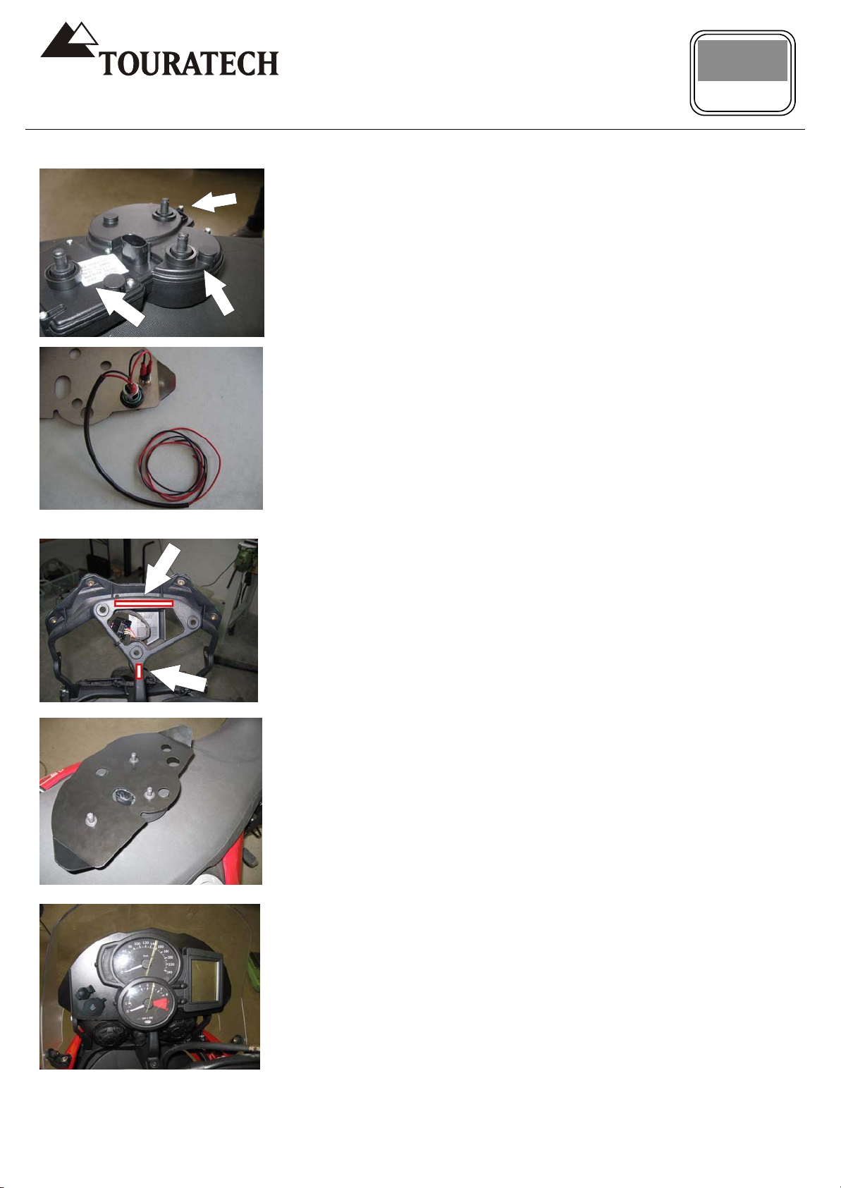
1. Demontieren Sie zuerst die
Frontscheibe. Dazu entfernen Sie die
vorderen und seitlichen Schrauben der
Scheibe (siehe Bild 1 u. 2)
2. Für die leichtere Demontage entfernen
Sie die Schrauben links und rechts an der
Scheinwerfer Halterung (siehe Bild 3).
Nun können Sie den Scheinwerfer nach
vorne schieben und ihn vorsichtig auf den
Kotflügel legen (Achtung! Bitte ein
sauberes Tuch unterlegen um Kratzer im
Lack zu vermeiden).
3. Wenn Sie nun von vorne auf die
Cockpiteinheit schauen sehen sie 3
Schnellverschlüsse (Clips) welche die
Cockpiteinheit festklemmen (siehe Bild 4).
Entfernen Sie diese indem Sie sie zur
geschlossenen Seite abziehen. Am besten
geht dies mit einer kleinen Spitzzange).
Nun können Sie das gesamte Cockpit
nach hinten abziehen.
4. Ziehen Sie den Stecker vom Cockpit ab
indem sie die Sicherung der Haltelaschen
auf beiden Seiten etwas
zusammendrücken (siehe Bild 5).
Achtung! Wichtige Hinweise:
Bei allen Arbeiten Zündung aus und die
Batterie abklemmen
Lieferumfang:
1x Instrumentenabdeckung
1x Buchse klein
1x Buchse mittel
1x Buchse gross
2x Bordnetzsteckdose
2 x Kabelabzweiger
4 x Kabelverbinder Buchse
2 x Anschlussleitung (rot u. Schwarz)
1 x Sicherungshalter
1 x Flachsicherungseinsatz 15A blau
1 x Moosgummistreifen (10mm x 15mm)
1 x Moosgummistreifen (10mm x 70mm)
1 x Isolierschlauch
01-048-0431-0
Anleitung: Instrumentenabdeckung
BMW F 650(Twin)/800 GS
These instructions are at our present level of
knowledge. Legal requirements for correctness do not
exist. Technical issues subject to change.
DE20080424
3
1
2
3
4
5
Installation Instruction: Cockpit
Cover BMW F650(Twin)/800GS
Assembly:
1. Disassemble the windscreen by
removing the screws at front and on the
sides (see photo 1 and 2).
2. For easier disassembly remove also
the left and right screws of the headlight
bracket (see photo 3).
Pull the headlight forward and set it
carefully on the front fender (Attention!
Use cloth under headlight to avoid
scratching on fender paint!)
3. Remove the three quick release
circlips that hold the instrument unit
behind the cockpit (see photo 4).
Needle nose pliers are a good tool for
clips removal.
Pull then the complete instrument unit
back and off.
4. Disconnect the cockpit plug by
pressing the latches together on the
sides (see photo 5).
Attention! Important tip, information:
Turn ignition off and disconnect
battery during installation!
Contains:
1 x Cockpit cover
1 x Bushing small
1 x Bushing medium
1 x Bushing large
2 x Accessory outlet socket
2 x Cable connector
4 x Blade connector
2 x Connection cable (red and black)
1 x Fuse carrier
1 x Fuse 15A blue
1 x Cellular rubber strip
1 x Wire isolation tubing
(10mm x 15mm)
1 x Cellular rubber strip (10mm x 70mm)
May 2009
Diese Anleitung ist nach unserem derzeitigen Kenntnis-
stand verfasst. RechtlicheAnsprüche auf Richtigkeit
bestehen nicht. Technische Änderungen vorbehalten.
Sehen Sie auchin unserem Katalog
oder im Internetunter www.touratech.com
DIN EN ISO9001:2000
Zertifikat 15 10042285
5. Nun legen Sie, wie im Bild 6 gezeigt, die
Abstandshülsen hinten auf das Cockpit. 1
kleine Buchse, 2 mittlere Buchse, 3 große
Buchse.
6. Bevor Sie nun die Instrumentenblende
auflegen Schrauben Sie die Steckdose wie
in Bild 7 in der Blende fest.
Schließen Sie das rote Kabel an den
inneren Kontakt der mitgelieferten
Steckdosen an, das schwarze dem
entsprechend an den äußeren Kontakt.
7. Kleben Sie die Moosgummistreifen wie
in Bild 8 beschrieben auf den
Cockpitträger.
8. Nun legen Sie die Blende wie in Bild 9
gezeigt auf.
9. Stecken Sie das Cockpit wieder in die
dafür vorgesehenen Halterungen und
bauen Sie alles wieder in umgekehrter
Reihenfolge zusammen.
10. Es kann sein, dass die Anschlüsse an
den Steckdosen ein wenig gebogen
werden müssen, damit Sie die Blende
korrekt aufsetzen können. Seien Sie dabei
vorsichtig, damit die Anschlüsse nicht
abreißen
1
1. Der Anschluss der Steckdosen an das
Bordnetz erfolgt mittels der beiden
Leitungen 1-Ader in rot und schwarz.
V
erlegen Sie diese zur Batterie und
schließen Sie sie dort mit Hilfe der
Ringösen an. Dabei sollte die
Bordnetzsteckdose mit Dauerplus oder
über das Zündschloss geschaltet mit S
versorgt werden soll.
Den Masseanschluss können Sie sowohl
an einer beliebigen Masseleitung, als auch
direkt an der Batterie vornehmen.
Ziehen Sie bitte über die beiden
Anschlussleitungen den beiliegenden
Isolierschlauch, um die Leitungen vor
Beschädigungen zu schützen.
01-048-0431-0
These instructions are at our present level of
knowledge. Legal requirements for correctness do not
exist. Technical issues subject to change.
DE20070122
6
3
2
1
7
8
9
5. Set now the spacer bushing behind
the instrument unit as shown in photo 6.
1 small bushing, 2 medium bushing and
3 large bushing.
6. Install the accessory outlet on on the
cockpit cover as shown in photo 7.
Connect the red cable to the contact
in the center of the 12V outlet and the
black cable to the outer contact.
7. Set the cellular rubber strips on the
back of the instrument unit as shown in
photo 8.
8. Place the cover like shown in photo 9.
9. Reconnect the cockpit plug and
reinstall cockpit unit in reverse order
with the circlips.
10. If nesseary bend the pins away from
the stem to avoid them toughing.
Be careful not to destroy the pins by
breaking.
11. Connect the accessory outlet with
battery, using supplied black and red
wires and connectors.
Our preferred wiring option is directly to
motorcycle battery so outlet can be used
for battery charging for example or to
run GPS when bike is not running. For
clarity use the red wire as positive lead
from the center blade on the back of the
accessory outlet to battery positive (over
fuse holder). Use the black wire as
ground wire from the outside accessory
outlet terminal to ground or battery
negative pole.
Route wires away from moving and hot
parts, through the protective tubing and
secure with cable ties.
May 2009Mai 2009
Other Touratech Automobile Accessories manuals


Popular Automobile Accessories manuals by other brands


ULTIMATE SPEED
ULTIMATE SPEED 279746 Assembly and Safety Advice

SSV Works
SSV Works DF-F65 manual

ULTIMATE SPEED
ULTIMATE SPEED CARBON Assembly and Safety Advice

Witter
Witter F174 Fitting instructions

WeatherTech
WeatherTech No-Drill installation instructions

TAUBENREUTHER
TAUBENREUTHER 1-336050 Installation instruction