tousek Pass 838 User manual

Installation and operating manual
Barrier PASS 838

- 2 - tousek / E_PASS-838_02 / 22. 10. 2018
Important warning and safety notes for installation and operation
• These installation- and operating instructions form an integral part of this product. They have been specically written for professional installers trained and
skilled in the trade and should be carefully read in their full length before carrying out the installation. It concerns the control only, not of the overall device
“automatic gate”. After the installation this manual has to be handed over to the user.
• Installation, connection, adjustments, putting into operation, and servicing may only be carried out by trained professionals in full accordance with these
installation- and operating instructions.
• The EU Machine Directive, laws and rules concerning the prevention of accidents, and laws and standards which are in force in the EU and in the individual
countries have to be strictly followed.
• The TOUSEK Ges.m.b.H. cannot be held liable for any claims resulting from disregards of the laws and standards in force during the installation and
operation.
• The product may only be used in accordance with its original purpose, for which it has been exclusively designed, and which is described in these installation
and operating instructions. The TOUSEK Ges.m.b.H. rejects any liability if the product is used in any way not fully conforming to its original purpose as
stated herein.
• The product is not suitable for installation in explosion-hazardous areas. The existance of inammable gas and steam is of great danger !
• The packaging materials (cardboard, plastic, EPS foam parts and lling material...) have to be properly disposed of in accordance with the applying recy-
cling- and environmental procection laws. They may be hazardous to children and therefore have to be stored out of children´s reach.
• Before beginning with the installation the installer has to make sure that all mechanical components of the gate facility, like carrier prole/rail, gate frame and
panels, guiding elements etc. are sufciently supportive and resistant for the purpose of gate automation. Check also whether the product has transport
damages.
• All electrical installations have to be made in full conformity with the applying rules and laws (e.g. using a fault current circuit breaker, proper grounding...).
• An all-pole disconnecting main switch with a contact opening-gap of minimum 3 mm has to be foreseen.
• When installing the safety device (photocells, safety edges, emergency-stops etc.) please comply with the valid direcitves/standards, the criteria of practical
rules of conduct, the installation environment, the operating logic of the system and the effected force of the motorised gate.
• The safety devices must secure possible bruise, shear and general danger areas of the motorised gate.
• After installation the proper function of the gate facility and the safety devices has to be checked.
• Place warning signs and notes of the valid regulations to indicate danger areas
• With each installation the identication data of the motorised gate has to be placed in a visible place.
• The electric motor heats up during operation. Therefore the device should only be touched after it has cooled off.
• Children have to be instructed, that the gate facility as well as the belonging parts may not be used improperly, e.g. for playing. Furthermore handheld
transmitters have to be kept in safe places and other impulse emitters as buttons and switches have to be installed out of children‘s reach.
• Only original spare- and replacement parts may be used for repair of the product.
• The TOUSEK Ges.m.b.H. rejects any liability for claims resulting from usage of the product in combination with components or devices which do not fully
conform to the applying safety laws and rules.
• The installer has to inform the user about all aspects of the automatic operation of the complete gate facility, as well as about emergency operation. The
installer further has to supply to the user all instructions relating to the safe operation of the gate facility. The installation and operating instructions also
have to be handed over to the user.
• The user has to be informed that he has to turn off the main power switch in case of malfunction of the product and that he can use the facility again after
repair and adjustment works have been completed.
• Please notice that the warranty will not be applicable if the label with the engine number has been removed or
damaged.
Maintenance
• Maintenance works have to be carried out according to our maintenance plan (page12).
This manual is the sole property of the TOUSEK Ges.m.b.H. and may not be made available to competitors. All rights reserved. No part of it may be reproduced without our prior
written permission. We will not accept liability for any claims resulting from misprints or errors. This edition of the manual replaces all earlier publications of the same.

tousek / E_PASS-838_02 / 22. 10. 2018 - 3 -
PASS 838 L6
1. General Barrier PASS 838
Characterstics
• electromechanical barrier operator for barrier width 3m to 6m
• for 230 V a.c. power supply
• suitable for continuous operation (100% duty cycle)
• emergency release mechanism
• sinusoidal motion
• technology without limit switches
• speed sensor
• rednished(RAL3000)sheetsteelhousingoptionalinINOX
• integrated control board ST 80 with clear text menu
through large, illuminated LCD screen
• adjustable soft stop
• ARSAutomaticReversalSystem
• integratedsafetyedgeresistanceevaluator8,2kΩforlowerboomedge
• output for boom magnetic clamp and boom lamp with free
denablelight/blinkingfunction
•
General features
The barrier operators work electro-mechanically and are available with aluminium barrier booms (length of 3–6m depending on
type).Thebarrierboomsarepaintedwhiteandhaveredreectivestickers.Thedriveunitbasicallyconsistsofamechanical
gearing combined with a 230V electric motor, a balancing spring and a speed sensor.
Allcomponentsarebuiltintoarobustrednished(onrequestalsosilvernishedresp.inINOX),lockablesteelhousing.
Incaseofapowerfailurethebarrierboomcanbeopenedandclosedmanuallyafterlooseningtheemergencyreleasehand
wheel. Due to its particularly massive execution and the very short opening and closing times, the Tousek PASS 838 barrier
operator has been designed to handle a large number of opening/closing cycles per day.
Optional accessories: base plate for barrier operator, (barrier boom) tip rest, base plate for (barrier boom) tip rest., pluggable
radioreceiver(tousekSTN),pluggableinductionloopdetector(ISD6)andbarrierboomgrid.
Technical Data
Barrier PASS- 838V-ST 838 L3-ST80 838 L4-ST80 838 L6-ST80
max. barrier width 3m 4,5m 6m
Opening-, closing time 1,5s 7s
Motor power supply 230Va.c.
Power consumption 400W
Duty cycle (mode S1) 100%
Max. cycles/day 2000 1000 500
Ambient temperature -20°C to +40°C
Condenser 14µF
Boomconguration at - (H x B) 116mm (with rubber prole) x 30mm round - Ø 85mm
IntegratedcontrolST80 ST 80V ST 80 ST 80 ST 80
Art.No. 11530360 11530330 11530340 11530350
possible equipment:
Boom
LED boom lamp
Pendulum arm or tip rest only tip rest
Barrier boom grid
Other allbarrieroperatorsPASS838areequippedwithanemergencyoperationhandwheel
Housing colour: red
Note: The mentioned values „max. cycles per day“ require regular maintenance work according to our
specications (depending on intensity of operation between 1 and 4 times per year)
The barrier PASS 838V-ST is only for vehicle trafc !

- 4 - tousek / E_PASS-838_02 / 22. 10. 2018
8
9
13
10
11
14
15
4
5
7
1
2
3
6
12
16
16a
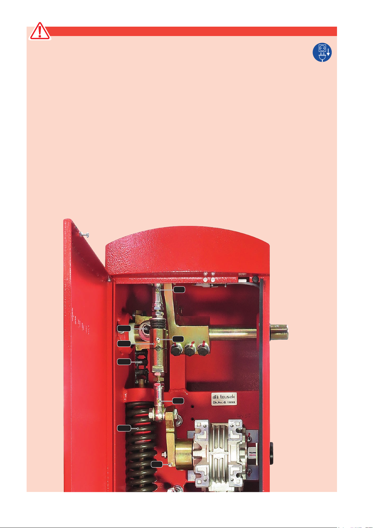
2. Technical layout Barrier PASS 838
Barrier in position „OPEN“
(1) housing door
(2) gearing lever
(3) chain
(4) gearing lever
(5) balancing spring
(6) euro standard lock cylinder
(7) earthing bolt
(8) activator bolt for door switch
(9) door safety switch
(10) drive shaft
(11) Limit bolt „boom OPEN“
(12) Limit bolt „boom CLOSED“
(13) emergency release
(14) reduction gearing
(15) drive motor
(16) electronic control with LC-Display menu
programming (16a)
Barrier in position „CLOSED“
2
tousek / E_PASS-838_02 / 22. 10. 2018 - 5 -
100
800
100
100
FB
F
S
T
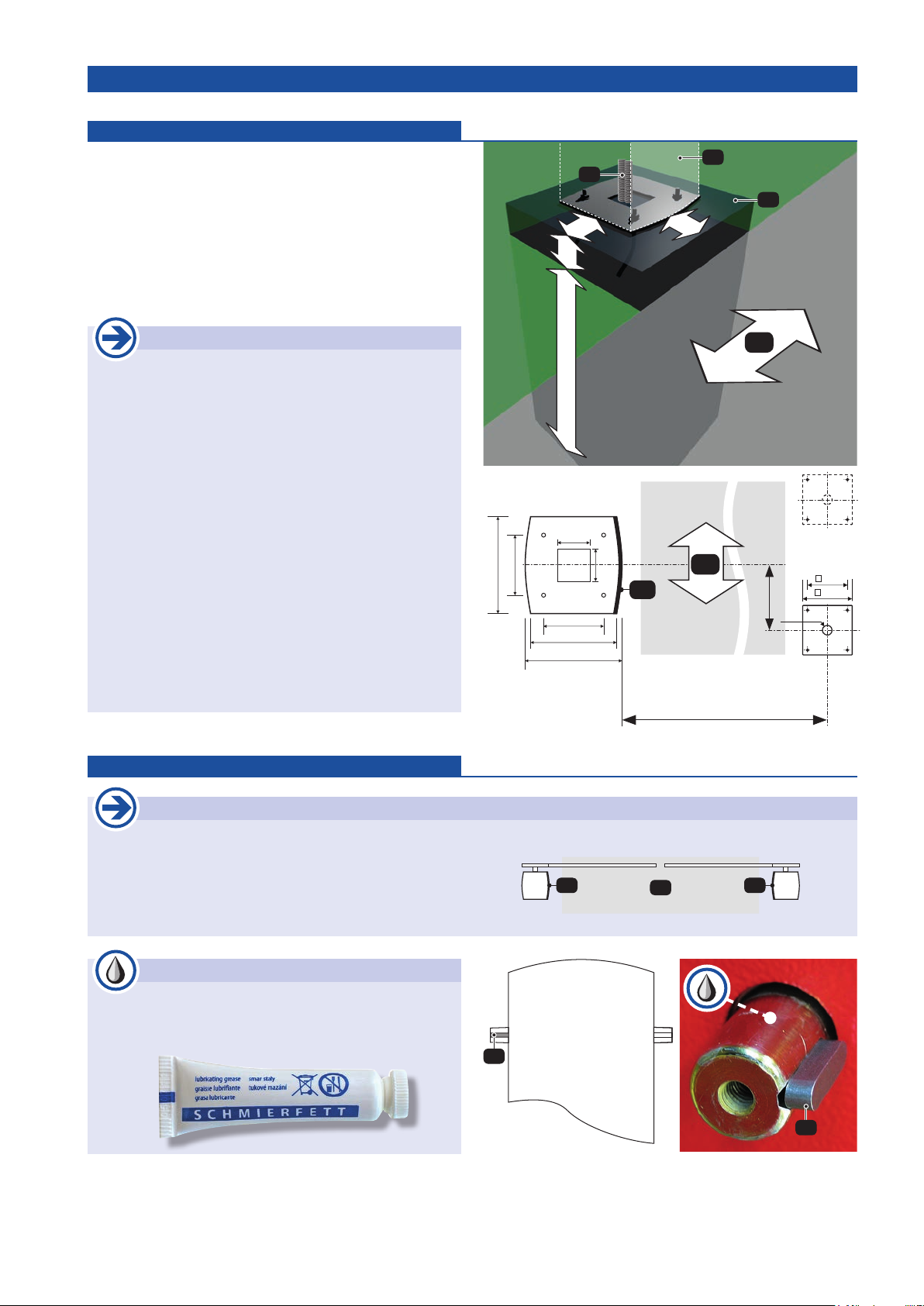
• Lead the insulating sleeves (S) for power supply and acces-
sories into the opening of the base plate.
• Embedthebaseplatermlyandhorizontallyinthefounda-
tion (F) (see „examples - Barrier installations“ page 13).
• Set the operator housing on the base plate with the door
(T) aligned to the road (FB) and secure it with the bolts.
Therefore it has to be ensured that the connecting cables
won’t be damaged.
3. Installation Barrier PASS 838
housing backside
3b. Mounting the barrier boom Installation
Important
• The barrier boom can be installed either on the left
or on the right side of the operator housing.
• Please do not load additional weight (e.g. sign boards)
on the barrier boom. This could result in the damage
of the gearbox unit.
left barrier right barrier
FB
T T
• Inarststepknockinametallkey(K) into the nut of the gearing drive shaft on the side of the barrier where you wish to
mount the boom.
• Thefollowingmountingstepsdifferinaccordanceofwhetheryouwishtomounttheroundortheatbarrierboom.
Important - grease the drive shaft
• put some grease onto the external drive shaft with
provided grease!
(see picture))
Foundation
• The foundations to be made must be at least 100mm
larger around then the foundation plates concerned.
• The foundation must be raised from the ground level to
a minimum of 100mm.
• The foundation depth from ground level to should have
a minimum of 800mm (frost resistant).
• The foundation always has to be adjusted to the structure
of the ground.
It should consist ofconcrete quality C20/25 at ground
class 3. The foundation has to be horizontal and free
of cracks.
• When using a support fork/tip rest pay attention to the
offset V, which depends on the barrier used (barrier
boom):
For barriers with at boom: V = 190
For barrier type PASS 838 L6
(= barrier with round boom): V = 220
K
K
3a.
Mounting of base plate and barrier operator
Installation
= barrier width - 25mm
290
180
180
255
290
100
100
base plate
barrier operator
V
T120
150
Ø30
FB
base plate
guide in bracket

- 6 - tousek / E_PASS-838_02 / 22. 10. 2018
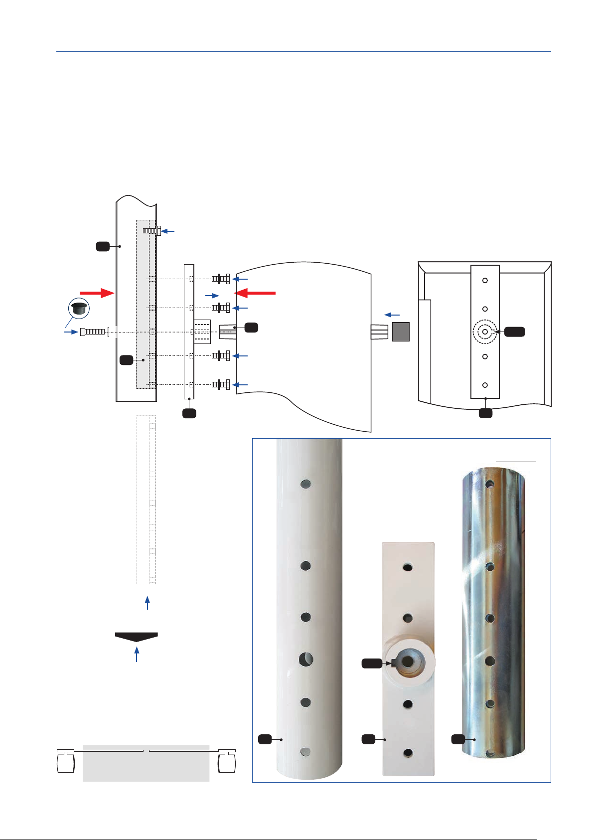
Push the barrier boom carrier (M) onto the drive shaft (A), so that the knocked-in metal key drives into the nut (M.N).
Now slide the slide-in module (E) as shown into the boom so that the drillings fall in line with the boom.
Then bolt 4 x (with discs) the boom carrier (M) with the slide-in module inside boom (E).
Now connect the boom (B) with cylinder head bolt (M10 x 40) and disc with drive shaft (A) (close the opening of boom
with plastic plug)
Attach the plastic covers onto the boom and drive shaft end.
Fixing the at boom (example as left barrier)
M
housing backside
(example shows boom mount for
left barrier)
left barrier right barrier
S1 S2
View S2
(Arrangement of mounting parts for left barrier)
Balkenoberseite
Important
• make sure to slide the slide in module (E) for both
mounting types (left/right) into the boom so that the
dropping (E.S) for the cylinder head bolt turns away
from barrier housing.
E
E.S
B
View S1
(boom carrier)
View S1
M.N
M
4 x
M
A
E
B
M.N
tousek / E_PASS-838_02 / 22. 10. 2018 - 7 -
Attachment of round barrier boom (example as left barrier)
Push the barrier boom carrier (M) onto the drive shaft (A), so that the knocked-in metal key drives into the nut (M.N).
Now slide the slide-in module (E) as shown into the boom so that the drillings fall in line with the boom.
Then bolt 4 x (with discs) the boom carrier (M) with the slide-in module inside boom (E).
Now connect the boom (B) with cylinder head bolt (M10 x 40) and disc with drive shaft (A)
(close the opening of boom with plastic plugs)
Attach the plastic covers onto the boom and drive shaft end.
E
S1 S2
housing back side
(example shows boom mounting
of a left barrier)
View S1
(boom carrier)
left barrier right barrier M
boom top
B
View S2
(Arrangement of mounting parts for left barrier)
M.N
M
M
E
B
A
M.N

- 8 - tousek / E_PASS-838_02 / 22. 10. 2018
SI
F
M
G
3e. Force adjusment
• The force adjustment is made by the ST80 control board.
• Due to the spring balance, the operator force is measured
in a way, that the barrier boom may be stopped with little
effort.
• As an additional safety device we recommend the connection
of a photocell.
3c. Electrical connections Installation
• Before carrying out the electrical connections, thepower
supply of the gate facility must be turned off !
• Connect the operator to the control unit according corre-
sponding control manual (mind the beside installation
notes).
• For the connection of diverse safetydevices, transmitters and
other accessories please check the corresponding manuals
(please note cable/wire plan).
Warning
• Before carrying out the electrical connections, the power supply of the gate facility must be turned off !
• The safety regulations for electric shock prevention have to be complied.
• The device should only be connected by qualied personnel
• The device should not be used in an explosive environment !
• An all-pole disconnecting mains switch with a contact opening gap of min. 3 mm has to be foreseen.
The gate facility has to be secured according to the valid safety regulations!
• IMPORTANT: The control lines (buttons, radio, photocells, etc.) have to be laid separately
from the 230V lines (supply line, motors, signal lamp). and may have a max. length of 50m.
For length > 50m decoupling steps are necessary !
Important installation notes
• Attention: The operator works with the condenser
mounted on the motor. Therefore don´t connect an
additional condenser to the control unit.
• The operator housing isequipped with asafety switch
(S) which stops the motor as soon as the housing
lid is opened. This safety switch must be connected
to the motor control unit (input for STOP switch).
3d. Adjustment of spring tension Installation
• The adjustment of spring tension is made by turning the
screw nut (M) on the spring rod.
Warning
• The safety standards and regulations regarding the
force adjustment have to be in compliance with the
effective rules !
Important
• The spring (F) has to be adjusted so that the boom
can be moved easily by hand in emergency release
state. (with pendulum arm and/or boom grid).
The boom should have a position of approx.
20–40°.

tousek / E_PASS-838_02 / 22. 10. 2018 - 9 -
3f. Adjusting the limits Montage
• Thebarrieroperatorisequippedwithtwo adjustablelimit
stop bolts, one for OPEN (AO) and one for CLOSED (AG)
position.
• The gearing lever (G)isbeingdenedinitsturningmove-
ment by these two limit stop bolts in the end positions open
and close. The integrated speed sensor registrates when it
reaches one of the limits, whereupon the control board turns
off the motor.
• The switching time and also the boom limit positions can be
denedbyboltinginoroutthelimitstopbolts.
Note
• Please note that when the limit stop bolts are being
adjusted (AO or AG) the limit positions are being
learned in.
• Choose in control board menu of ST 80 under
„DIAGNOSIS / delete position“ the value „YES“ .
T
AO
AG
G
IMPORTANT
• The end position of the barrier must take place according to the above services mentioned above description.
• Never use a support fork or pendulum support as a limit. These serve only to discharge of the bar!
• The company Tousek Ges.m.b.H. accepts no liability for damages resulting from such a misuse!

- 10 - tousek / E_PASS-838_02 / 22. 10. 2018
5. Attachment
of warning signs
• Additionaly to the safety installations of the barrier as
suggested by safety instructions in effect, some warning
signs have to be installed to warn pedestrians, bicycle
drivers etc. showing special attention and informing
of possible danger and for guidance to an alternative
route.
ATTENTION
AUTOMATIC BARRIER
RELEASE LOCKING
• Open the housing door and slide the cover of the emergency
release in direction of front part of housing.
• Insertthe10mmAllanKeyandturnit2–3timescounter
clockwise. This disengages the gear lever (G) from the
gearing transmission.
• The operator is now unlocked and the boom may be moved
manually (slowly ! - not faster than with the operator).
• To restore operation of the motor pull the emergency release
clockwiseagainrmly.
Move the boom a little so that the lever gear snaps into the
gearing.
• The lever gear (G) must rest again directly on the gearing
unit.
• After closing the housing door and turning on the power
supply, the motorised mode can be engaged again.
2–3x
Release
G
Locking
tighten
+
G
Acute risk of injury
The operator may only be emergency released if:
>>> the power supply is turned off and >>> the barrier boom is mounted
• Turn off power supply
of gate facility!
• ATTENTION: Make sure that the barrier boom is mounted!
• Ifthebarrierboomisremoved,thereisnocounterweighttothespring
tension. In this case the operator may not be emergency released
since this could lead to SERIOUS INJURIES !
4. Emergency release of the operator at power failure PASS 838

tousek / E_PASS-838_02 / 22. 10. 2018 - 11 -
14E
7
8
2x0,75 mm2
4x0,75 mm2
4S
3
5
4x0,75 mm2
min. 3x1,5 mm2
2
6
Koaxialkabel2x0,75 mm2
Warning note
Please be aware that the above picture is only a symbolic sample illustration
of a gate facility and may therefore not show all safety devices required for
your specic application.
To achieve an optimum safety level at your gate facility, please make sure
that all safety components and accessories which - according to the applying
safety rules and laws - are required in your particular case (e.g. photocells,
induction loops, sensing edges, signal lamps, trafc lights, mains- and emer-
gency power off switches etc.) are properly installed, operated, and serviced.
All possible bruise, shear and general danger areas of the motorised gate
have to be secured.
In this context please follow the EU Machine Directive, accident prevention
rules and laws, as well as applying EU- and national standards in force at the
time of installation and operation of the gate facility.
The Tousek Ges.m.b.H. cannot be held responsible for any consequences
resulting from disregard of applying standards and laws during installation
or operation of the gate facility..
Note concerning cable laying
• The electric cables have to be laid in insulating sleeves
which are suitable for underground usage. The insulating
sleeves have to be lead into the inner of the operator
housing.
• The control lines (buttons, radio, photocells, etc.) have
to be laid separately from the 230V lines (supply line,
motors,signallamp).and may have a max. length of 50m.
For length > 50m decoupling steps are necessary !
• Only double-insulated cables, which are suitable
for underground usage (e.g. E-YY-J) may be used.
In case that special regulations require another type
of cable, cables according to these regulations have
to be used.
6. Cable plan Barrier PASS 838
The 0,75mm2 control lines are shown without ground
lead. In order to facilitate connections we recommend
using exible wires and not using thicker wires for the
control lines.
1barrier operator Tousek PASS 838
2electronic logic control with optional available
radio receiver (plugable)
3main power switch
Note: An all-pole disconnecting main switch with a
contact opening-gap of minimum 3 mm has to be
foreseen
4 photocell(T:transmitter,R:receiver)
5pushbutton or key-operated momentary contact switch
6barrier housing signal lamp
7antenna (connection to radio receiver with coaxial cable)
8supply with fuse max. 13A
- 12 - tousek / E_PASS-838_02 / 22. 10. 2018
7. Maintenance plan for barrier PASS 838
Maintenance works may only be carried out by trained professionals.
ATTENTION: Before carrying out maintenance works, turn off the power supply.
According to the frequency of actuation the following works have to be carried out 1–4 times a year:
•Checkthecorrectxingofthebarrierhousing.
• Check the balancing spring, adjust if necessary.
• Grease the guiding rod of the balancing spring.
• Grease the grease nipples (N1–N4) with the grease press.
• Check and adjust the end positions opened and closed.
• Check the proper function of the emergency release.
• Check the proper function of the housing lid safety switch.
• Check the gearing on tightness.
• Check if the assembly bolts of the gearing are properly secured.
• Check barrier boom support: - proper seat of support at the main shaft
- proper seat of the 4 internal assembly bolts
• Optical inspection of ball bearings of main shaft.
• Check force adjustment of control unit.
• Check all safety devices and accessories.
• Equalising spring (W1), chain hoist device (W2) disc spring (w3) and fastening bolt M14 (W4)
have to renewed every 200.000 cycles (latest every 3 years) !
W2
W3
W1
W4
N1
N3
N2
N4

tousek / E_PASS-838_02 / 22. 10. 2018 - 13 -
V
120
150
Ø30
190
(L6: 220)
290
255
180
290
180
Foundation plate
PASS 838
Foundation plate
Tip rest/support fork
40
80
390
330
210
3000
120
150
Ø30
190
(L6: 220)
290
255
180
290
180
Foundation plate
PASS 838
Foundation plate
Tip rest/support fork
40 80
390
330
210
3000
Foundation plate
ImpulsepillarV03
Foundation plate
ImpulsecolumnV03
Distance depending
on road width
Distance depending
on road width
V
2
2
1
1
5
5
100
100
100
100
Ø70
Ø70
8. Barrier installations - Examples Barrier PASS 838
• Dimensions in mm
2
2
1
1
3
3
4
4
5
5
(1) Barriers PASS 838
(2)Impulsecolumns
(3) Photocells
(4)Inductionloops
(5) Tip rests/support forks
(6) Photocell pillars
Important
• The foundations to be made must be at least
100mmlarger around then the foundation plates
concerned.
• The foundation must be raised from the ground
level to a minimum of 100mm.
• The foundation depth from groundlevel to should
have a minimum of 800mm (frost resistant).
• The foundation always has to be adjusted to the
structure of the ground.
It should consist of concrete quality C20/25
at ground class 3. The foundation has to be
horizontal and free of cracks.
• When using a support fork/tip rest pay attention
to the offset V, which depends on the barrier
used (barrier boom):
For barriers with at boom: V = 190
For barrier type PASS 838 L6
(= barrier with round boom): V = 220
Single barrier with support fork and photocell pillars
Barrier system for separate entrance / exit with impulse columns V03
1
5
66
V
120
150
Ø30
190
(L6: 220)
290
255
180
290
180
Foundation plate
PASS 838
Foundation plate
Tip rest/support fork
390
Foundation plate
Photocell pillar Foundation plate
Photocell pillar
120
150
120
150
Distance depending on road width
Distance depending
on road width
Ø30Ø30
100
100
1
(F) foundation
(S) insulating sleeves
(T) housing door
(FB) road
100
800
100
100
FB
T
S
F
- 14 - tousek / E_PASS-838_02 / 22. 10. 2018
• dimensions in mm
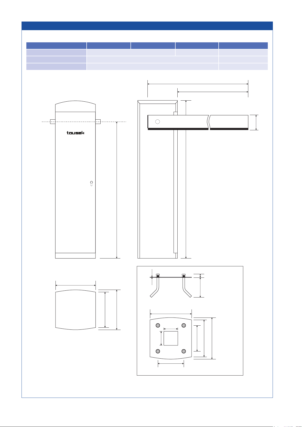
9. Dimensioned drawing Barrier PASS 838
measuresandtechnicalmodicationssubjecttochange!
280
250
280
290
180
180
255
290
30
135
3
950
1100
116
100
100
base plate
barrier width
boom length
NOTE 838V-ST 838 L3-ST80 838 L4-ST80 838 L6-ST80
max. barrier width 3m 4,5m 6m
boom length barrier width + 220mm barrier width + 280mm
Boomconguration at - (h x w) 116mm (with rubber prole) x 30mm round - Ø 85mm

A U T O M A T I S C H E T O R A N T R I E B E
®
Einbauerklärung
im Sinne der EG-Maschinenrichtlinie 2006/42/EG,
Anhang II B für den Einbau einer unvollständigen Maschine
Hiermit erklären wir, dass das nachfolgend bezeichnete
Produkt aufgrund seiner Konzipierung und Bauart sowie
in der von uns in Verkehr gebrachten Ausführung den
grundlegenden Anforderungen der Maschinenrichtlinie
(2006/42/EG) entspricht.
Bei einer nicht mit uns abgestimmten Änderung der
Produkte verliert diese Erklärung ihre Gültigkeit.
Das Produkt:
Schiebetorantrieb PULL XR, X/o, XD/o
ist entwickelt, konstruiert und gefertigt in Übereinstimmung
mit der:
EG-Richtlinie Maschinen 2006/42/EG
EG-Richtlinie Niederspannung 2006/95/EG
EG-RichtlinieElektromagnetischeVerträglichkeit 2004/108/EG
Angewandte und herangezogene Normen und Spezifi-
kationen:
EN ISO 13849-1, PL-„c“
EN 60335-1
EN 60335-2/95
EN 61000-6-3
EN 61000-6-2
Folgende Anforderungen des Anhangs I der EG-Richlinie
2006/42/EG werden eingehalten:
1.1.2, 1.1.3, 1.1.5, 1.2.1, 1.2.2, 1.2.3, 1.2.6, 1.3.2, 1.3.4,
1.3.7, 1.5.1, 1.5.4, 1.5.6, 1.5.8, 1.7
Die speziellen technischen Unterlagen wurden gemäß
Anhang VII Teil B der EG- Maschinenrichtlinie 2006/42/EG
erstellt.
Wir verpflichten uns, diese den Marktüberwachungs-
behörden auf begründetes Verlangen innerhalb einer
angemessenen Zeit in elektronischer Form zu übermitteln.
Für die Zusammenstellung der technischen Unterlagen
ist bevollmächtigt:
TOUSEK Ges.m.b.H., A1230 Wien, Zetschegasse 1,
Österreich
Die unvollständige Maschine darf erst dann in Betrieb
genommen werden, wenn festgestellt wurde, dass die
Maschine, in die die unvollständige Maschine eingebaut
werden soll, den Bestimmungen der Maschinenrichlinie
2006/42/EG entspricht.
Eduard Tousek, Geschäftsführer Wien, 01. 01. 2013
Motornummer (Typenschild):
Sonstige Komponenten:
EG-Konformitätserklärung
im Sinne der EG-Maschinenrichtlinie 2006/42/EG,
Anhang II, Teil 1 A
Wenn die neben beschriebenenTorantriebe in Verbindung
mit einem Tor gebracht werden entsteht im Sinne der
EG-Richtlinie Maschine eine Maschine.
Einschlägige EG-Richtlinien:
Bauprodukte-Richtlinie 89/106/EWG
Maschinenrichlinie 2006/42/EG
Elektromagnetische Verträglichkeit 2004/108/EG
Niederspannungsrichtlinie 2006/95/EG
Hiermit erklären wir, dass das nachfolgend bezeichnete
Produkt aufgrund seiner Konzipierung und Bauart sowie
in der von uns in Verkehr gebrachten Ausführung den
grundlegenden Anforderungen der oben angeführten
EG-Richtlinien entspricht. Bei einer nicht mit uns abge-
stimmten Änderung der Produkte verliert diese Erklärung
ihre Gültigkeit.
Produkt:
Torbezeichnung
Antriebsbezeichnung
Die unvollständige Maschine darf erst dann in Betrieb
genommen werden, wenn festgestellt wurde, dass die
Maschine,
in die die unvollständige Maschine eingebaut
werden soll, den Bestimmungen der Maschinenrichlinie
2006/42/EG entspricht.
Ausführender Montagebetrieb
Adresse, PLZ, Ort
Datum / Unterschrift
Declaración de incorporación
enelsentidodelaDirectivaCEsobremáquinas2006/42/CE,
Anexo II B para la instalación de una máquina incompleta.
Declaramos que el producto descrito en este documento
cumple debido a su diseño y construcción y el producto
puesto en circulación por nosotros cumple con los requisi-
tos esenciales de la Directiva de Máquinas ( 2006/42/CE ).
Con cualquier modificación no autorizada del producto
esta declaración pierde su validez.
El producto:
Automatización para puerta corredera
PULL XR, X/o, XD/o
desarrollado , diseñado y fabricado de acuerdo con:
Directiva de Máquinas 2006/42/CE
CE Directiva de bajo voltaje 2006/95/EC
Directiva de compatibilidad electromagnética 2004/108/EC
Normas y especificaciones aplicadas y consultadas:
EN ISO 13849-1, PL-„c“
EN 60335-1
EN 60335-2/95
EN 61000-6-3
EN 61000-6-2
Se cumplen los requisitos del Anexo I de la Directiva
2006/42/CE:
1.1.2, 1.1.3, 1.1.5, 1.2.1, 1.2.2, 1.2.3, 1.2.6, 1.3.2, 1.3.4,
1.3.7, 1.5.1, 1.5.4, 1.5.6, 1.5.8, 1.7
Los documentos técnicos especiales fueron preparados
en conformidad con el anexo VII, parte B de la Directiva
CE sobre máquinas 2006/42/CE.
Nos comprometemos a presentar a las autoridades de
vigilancia del mercado a una razonada solicitud dentro
de un plazo razonable, en forma electrónica.
Para la preparación de la documentación técnica está
autorizada:
TOUSEK Ges.m.b.H., A1230 Viena, Zetschegasse 1,
Austria
La máquina incompleta no debe ser puesta en funcio-
namiento, si se ha constatado que la máquina en la cual
la máquina incompleta debe ser instalada no cumple
con las disposiciones de la Directiva de Máquinas
2006/42/CE en línea.
Eduard Tousek, Gerente Viena, 01. 01. 2013
Número de motor (placa de características):
Otros componentes:
Declaración de conformidad CE
enelsentidodelaDirectivaCEsobremáquinas2006/42/CE,
Anexo II, parte 1 A
Cuando los siguientes automatismos para puertas
descritos son asociados con una puerta entonces forman
en el sentido de la Directiva de máquinas CE una máquina.
Correspondientes directivas de la CE:
Productos para la Construcción de la Directiva 89/106/CEE
Directiva de Máquinas 2006/42/CE línea
Directiva de compatibilidad electromagnética 2004/108/EC
Directiva de bajo voltaje 2006/95/EC
Por la presente declaramos que el siguiente producto
designado cumple con los requisitos esenciales de las
anteriores directivas de la UE, tanto en su diseño y
construcción, como puestas en circulación por nosotros.
Con cualquier modificación no autorizada del producto
esta declaración pierde su validez.
Producto:
Denominación de la puerta
Denominación del automatismo
La máquina incompleta no debe ser puesta en funciona-
miento, si se ha constatado que la máquina en la cual la
máquina incompleta debe ser instalada no cumple con
las disposiciones de la Directiva de Máquinas 2006/42/
CE en línea.
Empresa de instalación
Dirección, código postal
Fecha / Firma
Declaration of incorporation
In compliance with EC Machine Directive 2006/42/EC,
Annex II B for the installation of an incomplete machine.
We hereby declare that the following product, as well
as its version, put by us into circulation, complies with
the essential requirements of the Machinery Directive
(2006/42/EC), due to its design and type of construction.
The validity of this declaration will cease in case of any
unauthorized modifications to the products.
The product:
Barrier operator PASS-838V, -838L3, -838L4, -838L6
is developed, designed and manufactured in accordance
with:
EG-Directive Machinery 2006/42/EG
EG-Directive Low Voltage 2014/35/EU
EG-Directive Electromagnetic compatibility 2014/30/EU
Applied and used standards and specifications:
EN ISO 13849-1, PL-„c“
EN 60335-1
EN 60335-2/95
EN 61000-6-3
EN 61000-6-2
Following requirements of Annex I of the EC Directive
2006/42/EC are met:
1.1.2, 1.1.3, 1.1.5, 1.2.1, 1.2.2, 1.2.3, 1.2.6, 1.3.2, 1.3.4,
1.3.7, 1.5.1, 1.5.4, 1.5.6, 1.5.8, 1.7
The relevant technical documentation is compiled in
accordance with Annex VII, Part B of the EC Machinery
Directive 2006/42/EC.
We undertake to submit it in electronic form and within a
reasonable time to the market surveillance authorities in
response to a duly substantiated request.
TOUSEK Ges.m.b.H., A1230 Wien, Zetschegasse 1,
Österreich
is authorized to compile the technical documentation.
The incomplete machine cannot be put into service, until it
is determined that the machine, into which the incomplete
machine has to be inserted, complies with the the Machine
Directive 2006/42/EC.
Eduard Tousek, CEO Vienna, 01. 01. 2013
Motor number (Type plate):
Other components:
EC Declaration of Conformity
In compliance with EC Machine Directive 2006/42/EC,
Annex II, Part 1 A.
When the described operators are connected to a
barrier system they form a machine in the sense of the
EC Machine Directive.
Relevant EU directives:
Construction Products Directive 89/106/EWG
Machinery Directive 2006/42/EG
Low Voltage directive 2014/35/EU
Electromagnetic compatibility 2014/30/EU
We hereby declare that the following product, in the version
put by us into circulation, complies with the essential requi-
rements of the Directives mentioned above. The validity
of this declaration will cease in case of any unauthorized
modifications to the products.
Product:
Motor description
Barrier width
The incomplete machine cannot be put into service, until it
is determined that the machine, into which the incomplete
machine has to be inserted, complies with the the Machine
Directive 2006/42/EC.
Installation company
Address, ZIP code, Place
Date/ Signature

your service partner:
Tousek Ges.m.b.H. Austria
A-1230 Vienna
Zetschegasse 1
Tel. +43/ 1/ 667 36 01
Fax +43/ 1/ 667 89 23
Tousek GmbH Germany
D-83395 Freilassing
Traunsteiner Straße 12
Tel. +49/ 8654/ 77 66-0
Fax +49/ 8654/ 57 196
Tousek Benelux NV
BE-3930 Hamont - Achel
Buitenheide 2A/ 1
Tel. +32/ 11/ 91 61 60
Fax +32/ 11/ 96 87 05
Tousek Sp. z o.o. Poland
PL 43-190 Mikołów (k/Katowic)
Gliwicka 67
Tel. +48/ 32/ 738 53 65
Fax +48/ 32/ 738 53 66
Tousek s.r.o. Czech Republic
CZ-130 00 Praha 3
Jagellonská 9
Tel. +420/ 2/ 2209 0980
Fax +420/ 2/ 2209 0989
We reserve the right to change dimensions and/or technical specications with-
out prior notice. Claims resulting from misprints or errors cannot be accepted.
tousek PRODUCTS
• sliding gate operators
• cantilever systems
• swing gate operators
• garage door operators
• folding door operators
• trac barriers
• electronic controls
• radio remote controls
• key operated switches
• access control
• safety devices
• accessories
tousek
E_PASS-838_02
22. 10. 2018
Table of contents


