TowerIQ TOWERLINQ User manual

TOWERLINQ
SYSTEM OVERVIEW
Designed for UL60950 certification
March 2023

BRIEF DESCRIPTION OF THE SYSTEM PURPOSE....................................... 2
General Description: ..................................................................................... 2
SYSTEM COMPOSITION AND PARAMETERS............................................. 3
System Purpose: .......................................................................................... 3
Operational Characteristics: ............................................................................ 3
PURPOSE OF DEVICES IN THE SYSTEM...................................................... 7
Brief ......................................................................................................... 7
System
Composition
.....................................................................................
8
TRANSCEIVER Devices
.................................................................................
8
Control Devices ........................................................................................... 8
Power Devices ............................................................................................. 8
PURPOSE OF CONNECTORS, CONNECTION OF DEVICES ..................... 10
OPERATING MODES, DESCRIPTION, PURPOSE...................................... 13
STANDBY radio mode
.................................................................................
13
MONITOR radio mode
................................................................................
14
ACTIVE radio mode
....................................................................................
14
INITIAL SETTING ......................................................................................... 15
Frequency Settings ......................................................................................15
Checking Antenna Status ..............................................................................15
PUTTING THE SYSTEM INTO OPERATION ................................................ 16
Checking Antenna Status ..............................................................................16
Apply settings, checking voice........................................................................17
APPENDIX A: ............................................................................................... 18
APPENDIX B1 .............................................................................................. 19
APPENDIX B2 .............................................................................................. 20
APPENDIX B3 .............................................................................................. 21
APPENDIX B4 .............................................................................................. 22
APPENDIX B5 .............................................................................................. 23
APPENDIX B6 .............................................................................................. 24
APPENDIX C: ............................................................................................... 25
APPENDIX D: ............................................................................................... 26
APPENDIX
D1
..............................................................................................
27
TO
C

BRIEF DESCRIPTION OF THE SYSTEM PURPOSE
General Description:
TowerlinQ is an active Distributed Antenna System (DAS) that may be used
as a substitution for a traditional passive DAS installation for Auxiliary Radio
Communication Systems (ARCS) in New York City. TowerlinQ meets all
FDNY and New York City Electrical and Building code requirements for ARCS
systems.
TowerlinQ consists of one or more Dedicated Radio Controller (DRC), a single
Node Controller or Hub, and a number of distributed active transceiver
NODE’s (up to 39). Each NODE provides reception of two narrowband radio
channels (uplink) in the ARCS frequency range (450 – 520 MHz), and
subsequent signal amplification, normalization, and retransmission as two
downlink channels for two-way radio communication within a single building.
The signal received by one TowerlinQ NODE (TQN) is transmitted by all other
TQN to ensure radio coverage throughout the entire building. The signals are
converted to digital form and are propagated through
the distributed network
based on 2-hour fire riser rated twisted pair cables instead of non-fireproof
coaxial cables used in ordinary DAS.
TowerlinQ system implements a Controller-Agent architecture. It includes one
TQN HUB transceiver and a custom number of TQN transceivers. All system
activities (data exchange, radio operation, etc.) are controlled by the HUB.
TQN only respond to HUB commands with a predefined response

behavior and data streams if present. In addition, the HUB responds to
external commands and transmits data via a command interface (Ethernet)
using an embedded web application.
SYSTEM COMPOSITION AND PARAMETERS
System Purpose:
■
The main feature differentiating feature of TowerlinQ versus
traditional ARCS systems is the distribution of digitized RF data over
2-hour fire and riser rated twisted pair cabling instead of traditional ½
inch coaxial cable. The TowerlinQ fire rate cable does not require
installation within 2 hour fire rated enclosure which is time consuming
and costly while limiting installation options in pre-existing buildings.
■
This system is intended to be installed in high-rise buildings in
accordance with New York City code requirements.
■
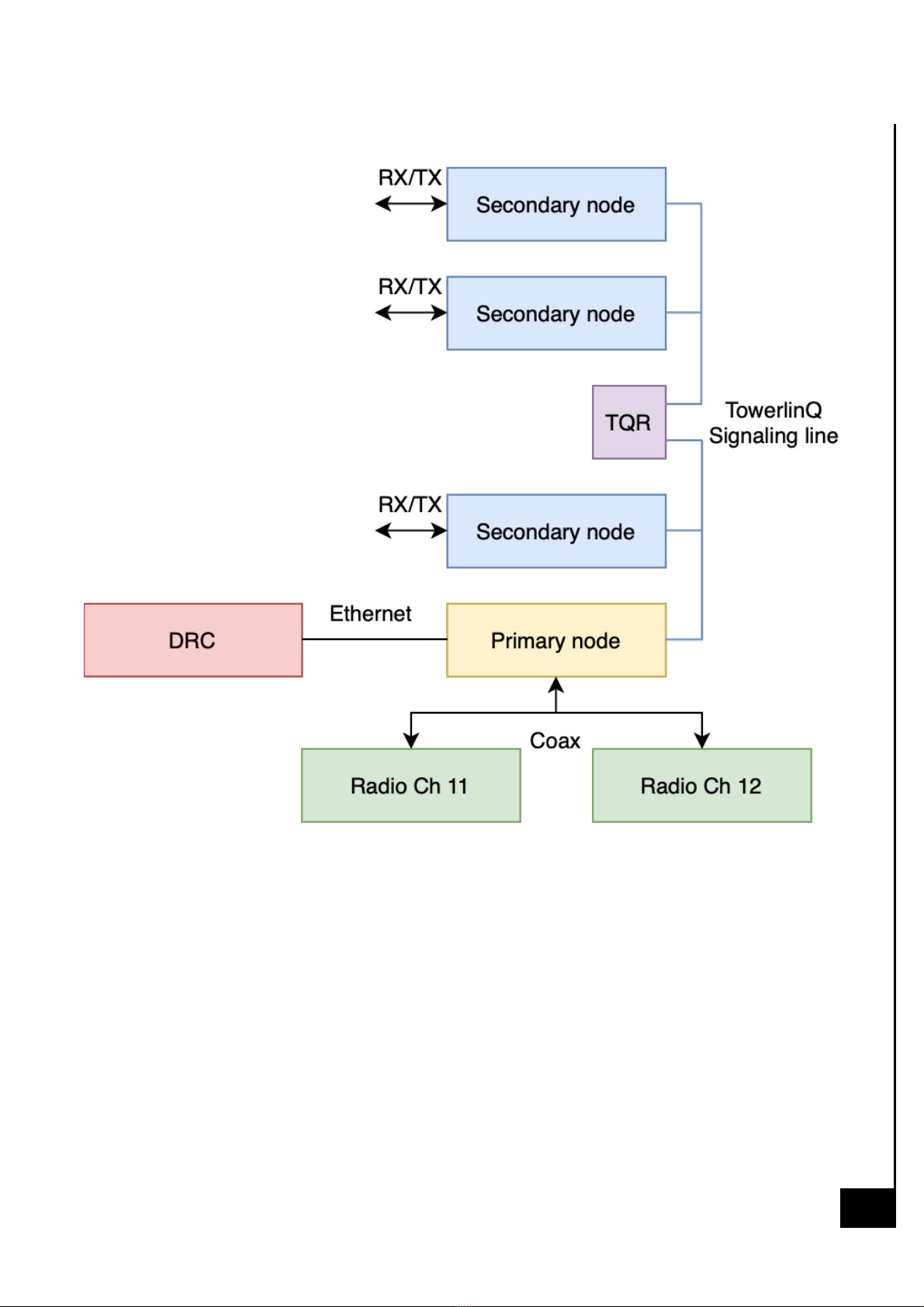
The system is designed to operate as point-to-multipoint RF bi-
directional repeater. Expected system topology is following: (see
APPENDIX A).
Operational Characteristics:
■
The system operates inside the building only and is configured to minimize
RF interference beyond the building enclosure.
■
The system is designed to stay online for at least one year before a required
annual inspection.
■
The system is designed to be powered by one or more 24VDC,
10A power supplies depending on the number of installed TQN
nodes.
■
The TowerlinQ system monitors power supply health (AC power input

and battery status) and will alarm upon loss or failure indication.
■
The system is designed to operate 24 hours in standby mode and 12
hours in active communication mode.
■
The power supply is equipped with a 720 Whr backup battery sufficient for 12
hours of continuous service in the event of loss of mains power.
■
The system is designed to be able to actively serve ARCS Channel 11
and Channel 12 simultaneously. Frequencies used for Channel 11
and Channel 12 are:
Channel 11:
■
Downlink: 483.0125 MHz
■
Uplink: 486.0125 MHz
■
Channel width (both downlink and uplink): 25 kHz
■
Max allowed output power: 30dBm
■
Required sensitivity: -95 dBm
■
Modulation: analog FM
■
Duplex: half-duplex
Channel 12:
■
Downlink: 484.7625 MHz
■
Uplink: 487.7625 MHz
■
Channel width (both downlink and uplink): 25 kHz
■
Max allowed output power: 30dBm
■
Required sensitivity: -95 dBm
■
Modulation: analog FM
■
Duplex: half-duplex

Note: Although both channels are half-duplex, simultaneous operation of
channel 11 and channel 12 implies overall duplex communication scheme,
since the TQN NODE can receive on channel 11 and transmit on channel 12
or vice-versa.
In order to achieve required isolation between RX and TX path, it is
allowed
to reduce output power of the TQN NODE to 15 dBm.
■
The System is designed to operate with folded dipole antennas.
Antenna specs:
Model: ANT450D
■
Dipole Antenna
■
Pattern: Adjustable, Offset Circular, Cardiod, Bi-Directional
■
Effective Gain: 1-2.5 dBd
■
Frequency Range: 406-512 MHz
■
Power Rating: 500 watts
■
Impedance: 50 Ohms
■
Vertical Beamwidth: 71 Degrees
■
VSWR: 1.5:1 or less
■
Dimension: 13 X 12 in.
■
Maximum Exposed Area: 0.27 ft.²
4

PURPOSE OF DEVICES IN THE SYSTEM
TowerlinQ - is a distributed active DAS auxiliary radio communication system
(ARCS). It's intended to be used as a substitution of passive distributed
antenna systems (DAS) in auxiliary radio communication systems. TowerlinQ
operates inside the building only and unlike traditional public safety radio
systems it does not provide communication outside the building.
TowerlinQ consists of one or more Dedicated Radio Controller (DRC), a single
TQN Node Controller or Hub, and a number of distributed active transceiver
TQN NODE’s (up to 39). Each TQN NODE provides reception of two
narrowband radio channels (uplink) in the ARCS frequency range (450 – 520
MHz), and subsequent signal amplification, normalization, and retransmission
as two downlink channels for two-way radio communication within a single
building.
The signal received by one TQN is transmitted by all other TQN to ensure
radio coverage throughout the entire building. The signals are converted to
digital form and are propagated through
the distributed network based on 2-
hour fire riser rated twisted pair cables instead of non-fireproof coaxial cables
used in ordinary DAS.
The TowerlinQ system consists of one or several Dedicated Radio Console
(DRC), up to 39 TQN TRANSCEIVERs, one of which serves as HUB, others -
as NODEs. Each TQN TRANSCEIVER includes two antennas, one receiving
and other transmitting. Additionally, the system can utilize one or several
Repeaters to
extend the operation distance.
(APPENDIX B1)
7

System Composition
The system includes devices:
TRANSCEIVER Devices
The TowerlinQ Node (TQN) is a universal TRANSCEIVER that can act as
both a HUB and a NODE. There can only be one HUB in a system. The
Hub’s role is to dispatch all data and commands within a system. There can
be up to 39 TQN NODEs per system. The number depends on a number of
TQN is determined by a number of parameters including coverage area and
building construction.
The TowerlinQ Repeater (TQR) is a signal repeater in the TowerlinQ network.
The repeater does not have a radio signal TRANSCEIVER. Its task is to
synchronize two physically separated sections of TowerlinQ networks. The
TQR is required to increase the length of the TowerlinQ network beyond the
standard 1000m cable length, and thereby increase the number of supported
TQN which also increases the RF coverage area as required by the building
square footage.
Control Devices
The Dedicated Radio Controller (DRC) is a system command/control unit with
voice handsets, information display and control buttons. The DRC is required
to display information about the system alarms, triggers, and manage the state
of the system.

Power Supply Devices
The TowerlinQ system requires an external power supply with battery backup
for 24VDC power and 12 hour active service in the event of mains power
loss. TowerIQ can provide the standard recommended Potter power supply
(PS10) for this purpose.
In the event of AC mains failure the PS10 can provide power to the system
from its own internal battery. When external AC power is available, it
charges its battery. Recommended load for each power supply is 3 TQN or
TQR devices. Thus, if there are a total of 30 devices in the first and second
groups, then 10 power supplies will be required. The distribution and
connection diagram must be viewed in accordance with the design
documentation.
8
9

PURPOSE OF CONNECTORS, CONNECTION OF DEVICES
Network (HUB)
“Network (HUB)” is used to connect HUB to the DRC (APPENDIX B2)
10
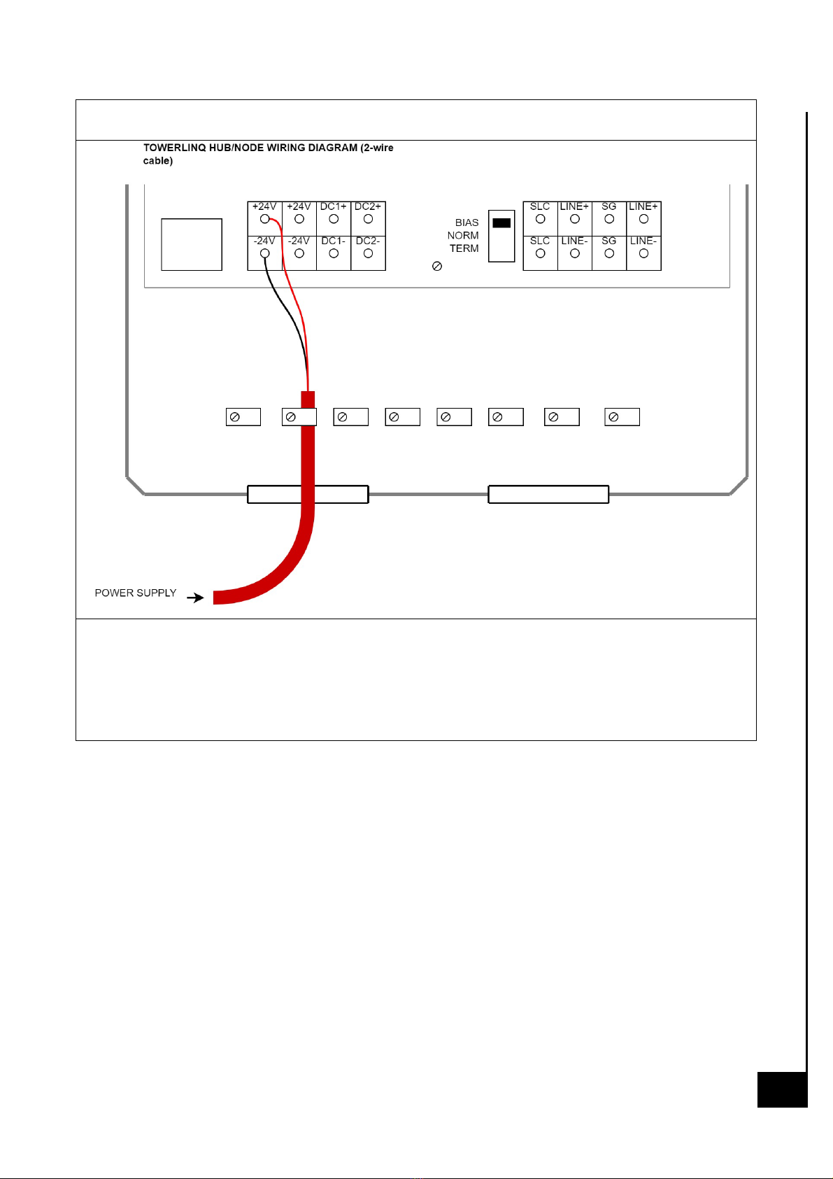
Power Supply (HUB/NODE)
“Power Supply (HUB/NODE)” is used to connect power to the HUB and
DRC (APPENDIX B3, B4)
11

Feedback (HUB/NODE)
“Feedback (HUB/NODE)” is used for battery feedback (APPENDIX B5, B6)
12

OPERATING MODES, DESCRIPTION, PURPOSE
MODE
DESCRIPTION
STANDBY
Radio signal must be
not transmitting from
radio to radio
MONITOR
Radio signal must be
not transmitting from
radio to radio
ACTIVE
Radio signal will be
transmitting from radio
to radio
STANDBY radio mode
The default Radio mode is Standby. In this mode all TQN radios are turned
off, no radio signal reception or transmission occurs, only network
communication, synchronization and control data exchange are transmitted
over the network.
!Please note that switching operating modes from SERVICE to NETWORK is
possible only through the WEB Configurator! (APPENDIX C)
13

MONITOR radio mode
In Monitoring radio mode the TQN HUB and TQN radio receivers are
enabled while transmitters are disabled. The network communication
protocol provides synchronization and control data exchange. The signal
received by any TQN is available externally on TQN HUB’s command
interface (Ethernet).
!In NETWORK mode, it is possible to change operating modes using the
switch on the front panel of the DRC!
ACTIVE radio mode
In Active radio mode each TQN enables its radios and starts to receive radio
signals. The TQN embedded software continuously calculates the received
signal strength (RSSI) and demodulates the in-band radio signaling signal
CTCSS (Continuous Tone-Controlled Selective Signaling) if present.
Both values are sent to TQN HUB. The TQN HUB selects the TQN with the
required CTCSS code and highest RSSI as the best signal source and
commands it to transmit digital radio data to other TQN via the Serial
Communication Line (Network). Any TQN receiving data through the
signaling line circuit will then transmit the data received via that interface over
the air.
!In SERVICE mode, changing modes is possible only through the WEB
Configurator!
14

INITIAL
SETTING
This section explains how to perform initial system settings using WEB
Configurator
(APPENDIX D)
!THE SYSTEM WILL NOT WORK UNTIL THE SERIAL NUMBERS OF THE
DEVICES ARE ENTERED!
Frequency Settings
Adjusting of frequencies and parameters of the HUB, replication of
parameters to TQN (APPENDIX D1)
Checking Antenna Status
!MAKE SURE THERE ARE NO ALARMS ON THE ANTENNAS!
15

PUTTING THE SYSTEM INTO OPERATION
Checking Antenna Status
It is possible to check the status of the antennas for each device. Make sure
there are no alarms on the antennas.
Possible causes of alarms:
■
antenna cable cut-off
■
antenna cable shortage
■
antenna on the metal surface
■
interference of TX/RX antennas
Steps:
1.
On the main screen, click on the tab with the name of your
configuration (TOWERLINQ for example).
2.
Scroll the page to the bottom.
3.
Check the aggregated alarm status
If antenna alarms are present, go to the "Network" tab and find the devices
that are causing this alarm. Check them sequentially to determine which is
problematic.
4.
Do this by entering the network and searching for devices with alarms.
16

5.
Check them one by one to determine which ones are causing problems
with the antenna.
6.
Fix the problem at the connection point using the instructions “Antenna
installation“.
Apply settings, checking voice
The Voice test can be done within the TQ network without TQN HUB.
Steps:
1.
On the main screen, click on the tab with the name of your
configuration (TOWERLINQ for example).
2.
Change the operation mode from “service“ to “network“, click
“Accept“ button.
3.
To emulate operation from DRC, change radio mode for channel 1
(CH1) in sequence standby>monitor>active
4.
For each mode use the 2 radios to check transmission and reception.
17
APPENDIX A:
18

APPENDIX B1:
19

APPENDIX B2:
20
Table of contents


 user guide")


