Tractel Tractelift Type II User manual

Rev.: 10/13 – NA Installation and maintenance manual ® Page 1 of 24
Copyright 2013, Tractel® P4795 NA all rights reserved.
™
*Patent N°: US12/718259

Rev.: 10/13 – NA Installation and maintenance manual ® Page 2 of 24
Copyright 2013, Tractel® P4795 NA all rights reserved.
Page
3
3
4-5
6
7
4.1 Components 7
4.2 Required tools 8
5.1 Driver unit 9
5.2 Diverter unit 10 - 11
5.3 Welding the round belt 12 - 16
5.4 Testing the welded joint 16
5.5 Connecting the optional removeable control panel 17 - 18
5.6 Connecting the power supply and function control 18
5.7 Test and guiding device assembly 18 - 19
5.8 Reporting to the log-book 19
6.1 Driver unit 20
6.2 Diverter unit 20
6.3 Round belt and guiding devices 20 - 21
6.4 Rope grab and spring snap connector 21
6.5 Remote Control 22
22 - 23

Rev.: 10/13 – NA Installation and maintenance manual ® Page 3 of 24
Copyright 2013, Tractel® P4795 NA all rights reserved.
Symbol Code Word Meaning Possible damage after noncompliance
Potentially
Potentially
Useful tips
for best operation none
Information for written Instruction to
(without code word)
8th edition: November, 2012
The manufacturer holds the copyright of this instal-
lation and maintenance manual.
51 Morgan Dr.
Norwood, MA 02062
USA
Telephone: (800) 421-0246
Fax: (781) 828-7600
internet: www.tractel.com

Rev.: 10/13 – NA Installation and maintenance manual ® Page 4 of 24
Copyright 2013, Tractel® P4795 NA all rights reserved.
This warning is your share or duties for achieving safety.
YOUR DUTY TO UNDERSTAND AND COMPLY
1. It is the responsibilty of the operator and their
employer to strictly read and conform to the instruc-
tions in this manual.
2. It is imperative for safety and efciency of op-
erations that this manual be read and
by the operator before using
the Tractelift™ Type II.
contained herein must be carefully and strictly
, including applicable Tractel safety
guidelines.
A copy of this manual must be available to the op-
erators at all times. Manual is to be posted in each
location where the system is used.
3. Should you hand over a remote, under whatever
conditions, to any party operating out of your con-
trol, you must provide a clean copy of this manual
and draw the other party’s attention that strictly
following all the instructions therein is a matter of
life or death.
4. Use of the Tractelift™ Type II may be only carried
out by persons, who are trained with the equip-
ment, and whose weight is
5. User must have received instruction by an ap-
proved Tractel® trainer to perform this task.
6.
Harness with appropriate life line
fall arrester used on a fall protection system (ANSI
Z359, CSA Z259 and PPE directive 89/686/CEE).
9.
. It shall only be used for assisting
persons, when climbing or descending a vertical
ladder.
10. Users must be familiar with the local safety and
health regulations, as well as with the instructions
of all personal protection equipment in use, and
have received appropriate instructions.
11. If the task is performed by employees, the con-
tractor has to follow the requirements of the
relevant safety and health regulations.
12. Only one person allowed to be connected during
use! Before use, you must READ and fully
understand the complete operating instructions!
13. Never use a Tractelift™ Type II which has been
modied.
14. Tractel® carries no liability for damage due to
noncandidate use of the Tractelift™ Type II, or
due to retrots and alterations on the equipment
or where non-original spare parts are used that
the company has not approved in writing.
YOUR DUTY TO INSPECT AND MAINTAIN
15. Keep this manual available at all times for easy
reference whenever required. Extra copies are
available from Tractel.
16. Carefully take notice of all the labels and name-
plates afxed to the Tractelift™ Type II . Never
operate the Tractelift™ Type II if any label or
nameplate, normally xed on the Tractelift™ Type
II is obscured or missing. Tractel® will supply extra
labels and nameplates on customer’s request.
17. The Tractelift™ Type II has to be maintained/in-
spected by a competent person, either on demand,
or at the latest after 12 months. The result of the
annual inspection has to be led in the log-book.
18. A careful and regular inspection of the Tractelift™
Type II, is part of the safety requirements. If you
have any questions, call Tractel®. (see back cover)
19. Do not use a Tractelift™ Type II with, damaged
assist rope.
20. Do not attempt to lengthen or repair the assist
rope.

Rev.: 10/13 – NA Installation and maintenance manual ® Page 5 of 24
Copyright 2013, Tractel® P4795 NA all rights reserved.
YOUR DUTY TO TRAIN AND CONTROL PEOPLE
21. An operator must not be assigned to a hosting job or to
rigging for the job, if the person is not:
a) mentally or physically t for that purpose
b) competent for the job to be performed
c) familiar with all application safety rules and require-
ments
d) trained for working under the above requirements
22. Never disassemble the Tractelift™ Type II by yourself or
by your staff. Except for the operations described in this
manual, the maintenance of the Tractelift™ Type II, as
well as disassembly and repair, must be exclusively done
by qualied repairers authorized in writing by Tractel®
Inc. for USA or Tractel® Ltd. for Canada. Tractelift™ Type
II spare parts in accordance with the serial number of
each machine must be exclusively utilized. No substitu-
tions are allowed.
23. Never let the Tractelift™ Type II and other equipment
of a system be managed or operated by a person other
than those authorized and assigned to the job.
24. Training operators must be set up by a competent
person, or of its technical consultant. According to the
working conditions, prior to putting the equipment into
operation, contact Tractel® Inc. for the USA or Tractel®
Ltd. for Canada. (see back cover)
25. Every job must be placed under the control of a per-
son having the required competence and the authority
for checking that all the instructions prescribed by this
manual be regularly and efciently carried out.
YOUR DUTY OF SAFETY BEYOND THE TRACTELIFT™
TYPE II
As being only one component of the system, the Tractelift™
Type II can contribute to the required SAFETY, IF:
26. It is tted on and with compatible equipment.
27. Other components meet the requirements of the ap-
plicable safety regulations and are of the proper quality,
and assembled to form a safe system.
28. Every support is stable, sufciently strong, according to
the load either static and dynamic.
29. Supporting structure provides the required resistance to
every load to be applied either static or dynamic, during
operating the equipment.
30. All the requirements in strength and resistance are ob-
tained with the necessary safety factor (see regulations
and professional standards).
31. All the calculations, design and subsequent work neces-
sary to the above requirements have been made by a
competent person on the basis of proper technical infor-
mation regarding the site.
32. Do not use the Tractelift™Type II or climb the ladder dur-
ing periods of severe weather or during electrical storms.
YOUR DUTY TO AVOID TAKING CHANCES
33. Tractelift™ Type II MUST NOT be used in explosive at-
mosphere. It has not been designed for such an applica-
tion.
AN ULTIMATE RECOMMENDATION
®
The companies of The Tractel
®
and their
appointed repairers will supply on request their
documentation regarding other Tractel
®
products
available: Lifting and pulling equipment and their
accessories, site and facade access equipment,
handling equipment, safety devices for load, per-
sonal fall protection equipment, load and tension
indicators, etc.
Go to
The Tractel
®
network can supply an after sales
and periodic inspection service.

Rev.: 10/13 – NA Installation and maintenance manual ® Page 6 of 24
Copyright 2013, Tractel® P4795 NA all rights reserved.
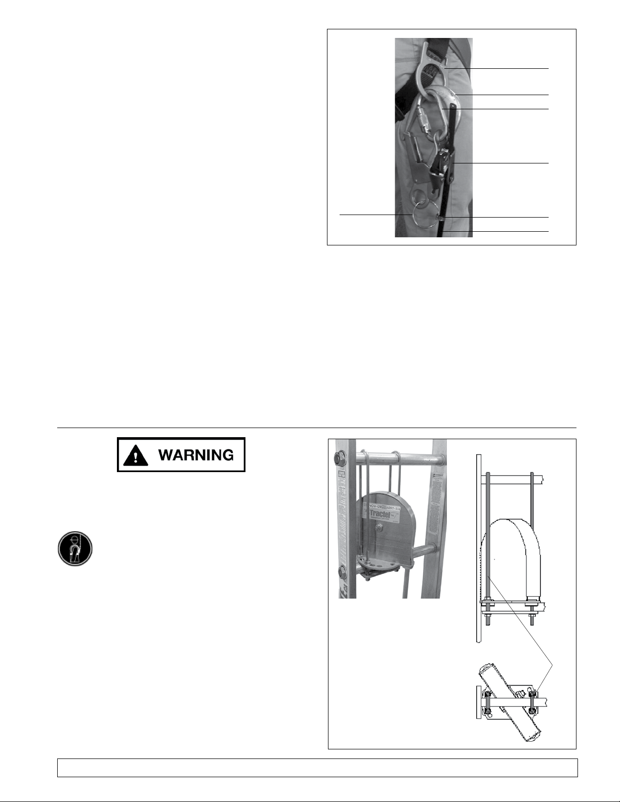
The Tractelift
™
Type II al-
leviates persons climbing a
vertical ladder (Fig. 1) with
adjustable pulling force ap-
proximately 60% of the of
the person’s weight entered
on the remote control. Two
user remotes are available,
Blue rubber casing for users
between 102 - 160lbs. (51
- 80 kg) and a Red rubber
casing for users between
160 and 250lbs. (80 kg -
125 kg).
The drive comes with a re-
mote control that is directly
connected with a Carabi-
neer and a rope grab to the
pulley belt. The other end
of this remote is attached
to the climbers approved safety harness with another
Carabineer.
Fig. 2
Fig. 4
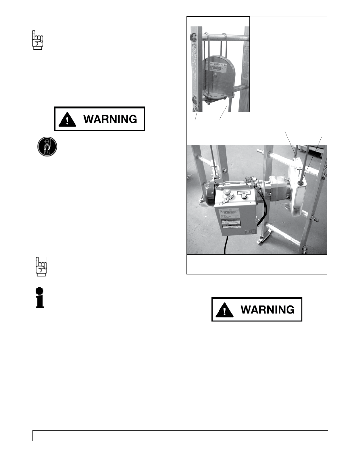
At the lower end of the ladder (Fig. 3), a motor with
that drives pretension endless round belt by means of
a driver pulley. Shown with and without the removable
control box in place.
The continuous welded round belt, made of special
synthetic material (Ø 1/2 inch / 12,5 mm) runs on the
driver pulley of the motor and a diverter pulley at the
upper end of the vertical ladder (Fig. 2).
The connection to the round belt is made by a belt grab,
xed to a locking carabiner, with the top of the remote
control attached, on the bottom side of the remote a
second carabiner is attached which attaches to the us-
ers safety harness. (Fig. 4).
Fig. 3
Round belt
Belt grab
Locking
carabiner
User
Remote
Locking
carabiner
This manual is valid for Tractelift™ Type II with remote
only.
Fig. 1

Rev.: 10/13 – NA Installation and maintenance manual ® Page 7 of 24
Copyright 2013, Tractel® P4795 NA all rights reserved.
This can be, for example, a fall arrest system with fall
arrest device on the middle pole of the ladder, connected
to the anchor ring of the harness.
The is
, but a part of the vertical ladder.
The shown pictures/drawings shall be understood as
examples.
Fall arrest
system
Climbing
Aid
Fig. 5
Fig. 6
Adjustable
positioning lanyard
a) The
b) to
the ladder ,
before starting with an installation:
– Attach the lanyard to one of the D-rings at the
waist belt, guide it behind the ladder, and attach
the other end to the second D-ring.
– Lock both locking carabiners.
– Adjust the length of the lanyard to get sufcient
freedom of movement for executing the installa-
tion.
The use of the positioning lanyard will reduce the pos-
sibility of fall, when leaning around the edge of the ladder
to install belt guides or similar.
Check completeness:
a)
b)
For standard ladders with including
.
c) on drum has sufcient length.
d) Belt for
– the ladder, and
– of the ladder, if there are obstacles.
.
e) For aluminum ladders:
Two .

Rev.: 10/13 – NA Installation and maintenance manual ® Page 8 of 24
Copyright 2013, Tractel® P4795 NA all rights reserved.
Check completeness
(Fig. 7)
1 Welding clamp with xing brackets
2 Welding iron
3 Special cutter
4 Cutter-knife
5 lever hoist 500lb. (250 kg)
with 10’ (3 m) of chain and manual
6 2 belt grabs with locking carabiner
7 ® dynamometer with 2 hooks
(440 lbs/200 kg1))
8 Thermometer
9 Pipe hook with key ring and hose clamp
10 Sling Ø 4.5 mm/ length 0.5 m
11 Tool box (not as shown)
a) 1 Set of socket wrenches 3/8” to 1 1/8” (10
to 30 mm) with extension
b) 1 Set of open end wrenches 3/8” to 1 1/8”
(10 / 13 / 19 / 30 mm)
c) 1 Socket spanner size 1/2” (10mm)
d) - Insulating tape
e) - Molycote® grease paste DX
f) 1 Walkie-talkies for communication
between the two installers. Walkie Talkies
must conform to local telecommunication
regulations.
Fig. 7

Rev.: 10/13 – NA Installation and maintenance manual ® Page 9 of 24
Copyright 2013, Tractel® P4795 NA all rights reserved.
Step
reinforcement
Apply Molycote® on all
: To avoid electro-
chemical corrosion
at those
places, where they might get in contact
with stainless-steel-components (screws or
guiding devices)!
On aluminum ladders, insert step reinforce-
ment to avoid deformation of the step, when
tensioning the round belt (Fig. 8a). The step
reinforcement should be on upper and lower
ladders rungs the upper and lower drive
pulleys are attached to.
Connect the driver pulley to the lowest possible
step (Fig. 8a - 8d).
Fig. 8a
Fig. 8b
Fig. 8c
The lower drive pulley should be attached to the
lowest possible step, by using the upper and lower
hardware (Fig. 8b-d). While attaching the lower
pulley the motor needs to be supported during
assembly. Sit the lower pulley on the lowest step
and tighten the two lower bolts through the lower
connector plate (Fig. 8c-d) into the pulley assem-
bly. Using the upper connector plate tighten the
two bolts into the top of the lower pulley assembly.
Tighten till the pulley is secure.
Fig. 8d
A
Rev.: 10/13 – NA Installation and maintenance manual ® Page 10 of 24
Copyright 2013, Tractel® P4795 NA all rights reserved.
Fig. 9
Pipe hook
Key ring Hose clamp
Round belt
a) Material and equipment to be taken with on the
ascent:
– pre-assembled
c/w anchoring parts;
for ladders with round steps incl. the
–
– and :
Socket size 1/2” 10 mm,
wrench/ratchet size 3/8” to 1 1/8” (13 mm and
19mm),
screw driver for the hose clamp,
Molycote® grease paste DX,
insulating band (only for aluminum-ladders)
–
(only for aluminum-ladders)
–
b) Connect the round belt’s end by means of the hose
clamp to the key ring of the pipe hook . As a backup
also attach the belt grab and carabiner to the round
belt. This carabiner and the pipe hook are then at-
tached to the lower D ring of the harness (g. 9).
a) The 1st installer connects the pipe hook and the
carabiner with the round belt to one of the D-rings
of its harness, and takes the rest of the material.
b) He secures himself to the climbing protection system
and starts climbing.
c) The 2nd installer watches the proper un-coiling of
the round belt from the hasp.
d) After arriving on top,
– Safely lay down the material on the platform.
– Take the round belt off the harness and secure
to the ladder by means of the pipe hook.
Fig. 10a
Fig. 10b
a) Align the pulley with the bottom pulley
b)
Before mounting the diverter make sure no moving
parts of the nacelle will obstruct with it. Fix the di-
verter unit at the highest two steps possible, (Fig.
10a). On steps use anchor brackets () to avoid
the diverter unit from tilting (Fig. 10b).
Belt grab
Harness D ring
Carabiner
Rev.: 10/13 – NA Installation and maintenance manual ® Page 11 of 24
Copyright 2013, Tractel® P4795 NA all rights reserved.
Fig. 11b
During the following steps, securely
hold the round belt to protect it against
falling down!
a) Open the hose clamp, take off the belt’s end, and
insert it at () in the entry bushing of the diverter
pulley, until it exits at () (Fig. 11a).
b) Fix the belt’s end again to the pipe hook.
c) Before starting with decent:
take off
of the , guide it
behind the ladder, and connect it in that way to a
free D-ring of the harness, that it will not interfere
during descent.
d) Guide the belt’s end
, and connect the pipe hook
to one of the D-rings of the harness – this makes
it easier to pull down the belt’s end.
e) The installer at ground level again watches the cor-
rect uncoiling of the round belt.
Fig. 11a
,
since it could be pulled upwards by the weight
of the belt hanging in front of the ladder.
f) At the places, where the ladder is connected to the
tower wall by brackets:
Unhook the rope grab from your harness, guide it
behind the bracket, and hook it up again to the har-
ness.
g) When reaching the ground, open the hose clamp
and remove the belt grab.
h) Introduce the belt’s end at () a n d
push it through between driver pulley
and guide cover, until it exits at ().
Pull the end out, until it is approx. 5 ft. (1.5 m) long.
In the next step, the Bravo™ lever hoist if
not used as directed may cause serious
injuries. You must read and understand
and follow all instructions in the manual
(included in the Installation Kit) before
beginning to weld the belt and using the
Bravo™ lever hoist

Rev.: 10/13 – NA Installation and maintenance manual ® Page 12 of 24
Copyright 2013, Tractel® P4795 NA all rights reserved.
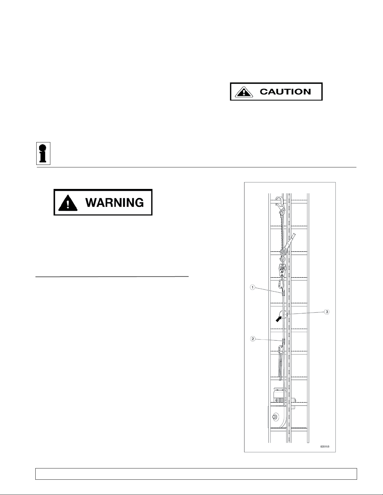
a) At the height () of the lower belt’s end (Fig. 12),
x the welding clamp with its xing bracket on a
ladder step (Fig. 13a).
b) Approx. 3 ft. (1 m) under the belt’s end, which comes
from the driver pulley, fasten a belt grab –
. (Fig. 12).
c) Approx. 10 ft. (3 m) above this clamp, fasten the
second belt grab to the round belt, which comes from
the top – (Fig.
12).
d) Anchor the chain hook of the Bravo™ lever hoist to
the locking carabiner of the upper rope grab, and
pull through by hand the chain as far as possible
(Fig. 13b). Check that the load chain has not become
twisted during installation. If twisted one of the links
could enter in the wrong position and damage the
hoist and the chain.
e) Anchor ® dynamometer between the top
hook of the lever hoist and the locking carabiner
of the lower belt grab (Fig. 13b).
Fig. 12
lower
belt grab
Fig. 13b
handifor®
bravo® lever
hoist
Fig. 13a
upper
belt grab
approx. 10 ft.
approx. 3 ft

Rev.: 10/13 – NA Installation and maintenance manual ® Page 13 of 24
Copyright 2013, Tractel® P4795 NA all rights reserved.
a) Switch on the dynamometer and push the tare-button
to set the display to zero.
b) Check the surrounding temperature.
c) With the lever hoist, tension the round belt
– to approx. 220 lbf (100 daN)
for temperatures above 32° F (≥ 0° C),
– to the value of table 1
for temperatures less than 32° F (below 0° C).
Before welding the round belt, it must be
. This requires
some time:
d) , watch the dynamom-
eter’s display, and to approx.
220 lbf (100 daN) (respectively the above dened
value for minus grades), until it stays stable.
,
:
If necessary, adjust tension until it is stable.
Table 1
1) When assembling at these temperatures you must get a dynamometer
with a (100 daN),
ex. a DYNAFOR® with a capacity of 500 lbs (250 kg):
Model LLX: Accuracy ±0,2 % / smallest load 0.5 lb, or
Model LLZ: Accuracy ±0,8 % / smallest load 1 lb.
Fig. 14a
Welding iron
a) Put the welding iron in a safe place, so it will not
interfere with the following preparation procedures
(Fig. 14a).
b) Connect the welding iron to power supply
and switch it on.
the welding iron
has reached 425º F or above the iron is at
.
(Fig. 14a).
Rev.: 10/13 – NA Installation and maintenance manual ® Page 14 of 24
Copyright 2013, Tractel® P4795 NA all rights reserved.
Cam lever
Clamping
screw
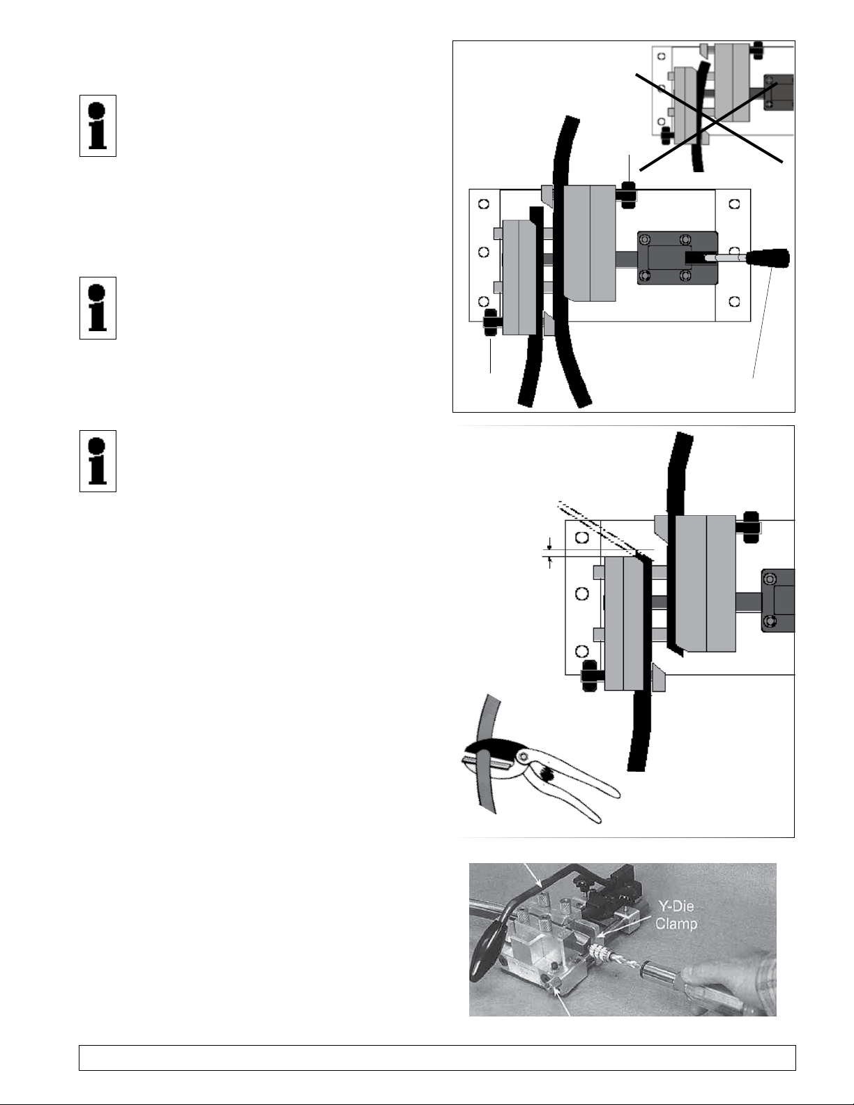
Fig. 15a
Special cutter
Fig. 15b
(Fig. 15a) – this
gets them lying parallel to the welding jaws
after xing them with the clamping screws.
a) With the cam lever completely open the welding
clamp, and if necessary, untwist the clamping screws,
until the belt can be inserted.
b) Insert the belt’s end coming from the driver unit into
the left clamp (Fig.15a).
If the belt’s end does not project over
welding clamp for at least 1/4 to 1/2 inch
(5 to 10 mm), push the complete pre-tensioned
belt upwards for the required distance.
c) Insert the belt coming from the top into the right
clamp, and tightly x both belts by means of the
clamping screws.
d)
Push the cam lever to the right, until the belts
get into contact, for two reasons:
1. To check, that the lever is not obstructed
during the welding procedure, and
2. to get practice – in particular on side rail
ladders – how to turn the cranked (off-set)
cam lever for quickly closing the welding
clamp, after the welding iron will be taken
off.
Completely re-open the welding clamp.
a) Using the special cutter, cut both belt ends according
to Fig. 15b:
– , and
– with .
This provides for a most complete contact to the
welding iron.
b) With the belt secure drill the core of each end with
a 1/32” drill bit to a depth of at least 3/16” (5mm)
(Fig. 16).
c)
Clamping
screw
Fig. 16

Rev.: 10/13 – NA Installation and maintenance manual ® Page 15 of 24
Copyright 2013, Tractel® P4795 NA all rights reserved.
a) ,put and hold the hot welding
iron between the belts’ ends (Fig. 17).
b) ,rmly push the cam lever
backwards and to the right to
(Fig. 18).
c) Making the weld joint
During this procedure, a lot of liqueed plastic
emerges from the clamp – , since
half of the material from both belts over the weld-
ing length has to be displaced
The index must be on the at
the right end of the coloured scale – it’s not until
then, that the welding clamp is completely locked
for the cooling down.
d) Safely lay down the welding iron for cooling down.
(See next page for cleaning the welding iron.)
Fig. 19
Fig. 18
Fig. 17
Index
Welding iron
Cam lever
Welding iron
2nd black marking
Welding burr
and excess material
Rev.: 10/13 – NA Installation and maintenance manual ® Page 16 of 24
Copyright 2013, Tractel® P4795 NA all rights reserved.
After cooling down of the weld joint:
a) Completely release the clamping screws, and
open the welding clamp by means of the cam
lever, so that the belt is free.
b) Release the lever hoist, take off the ®, switch
it off and store it in the sheath.
c) Take off the lever hoist, the welding clamp, and the
two belt grabs. Check that the load chain has not
become twisted during installation. If twisted one of
the links could enter in the wrong position and dam-
age the hoist and the chain.
d) If necessary, clean all tools, and store them in the
tool box.
e) Then,
, ex. with a cotton cloth, or once cooled it
can be removed by using one’s ngernails –
f) Store the welding iron in the tools box.
Risk of cuts use approved safety gloves
a) Cut off larger material remaining with the special
cutter, always cutting away from the body.
b) Using the cutter-knife trim the welding burr to get an
even round surface of the belt.
Warning of serious injuries if the welded joint
breaks when under load.
– Perform visual inspection and stress test in ac-
cordance with these instructions.
The welded joint must be tested after welding the
circular belt and deburring the welding seam:
If the following defects are visible to the naked eye
then the welded joint must be renewed:
• Excessive number of air inclusions
• Interruptions to the welding seam / seam not
completely closed
The edges of the fused belt must be cleanly weld-
ed closed along the entire length of the fused area.
See Fig. 20)
• Arrange the rope clamps (1) and (2) in such
a way that the welded joint (3) is positioned in
between them, as centrally as possible.
• Apply a tension of 100 daN (kg) to the welded
joint.
• The tension must be maintained for at least 5
minutes. Tensioning must not result in lateral
contraction of the welded joint.
• Repeat visual inspection.
Fig. 20

Rev.: 10/13 – NA Installation and maintenance manual ® Page 17 of 24
Copyright 2013, Tractel® P4795 NA all rights reserved.
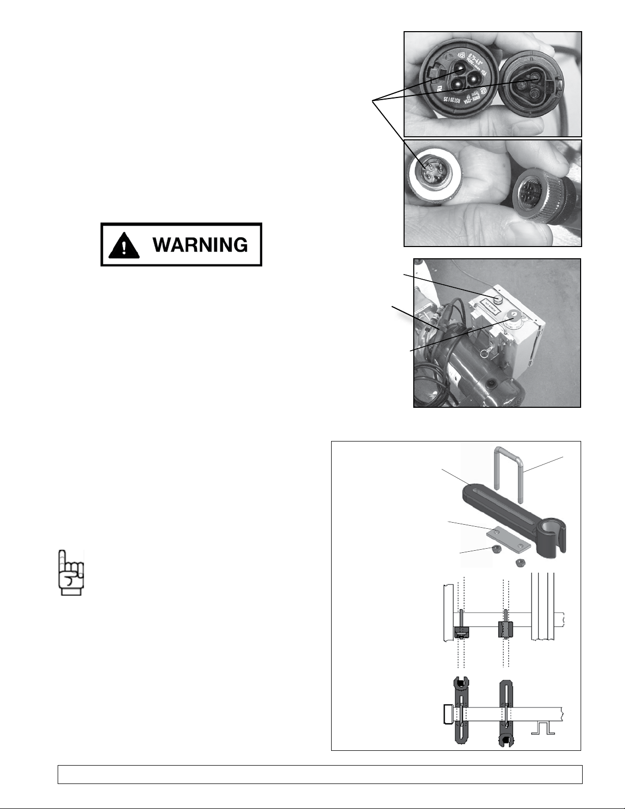
d) Once the control panel is in place, lock the panel
pin in place by twisting the pin. (Fig. 23 & 24).
e) Connect the two control cables together,
connection is by male and female connectors.
Both connectors have a positive tting (D)
connections and can only be connected in one
alignment only
(Fig. 25 & 26)
. The connector
should tighten completely.
(Fig. 28 item E)
a) Disconnect the power supply and the control cables
b) Disengage the panel pin and slide the control box
up off the mounting plate.
c) Place the control panel back into the carrying con-
tainer
Fig. 24 - LOCKEDFig. 23 - OPEN
a) With the lower pulley and motor installed the unit is
ready for the removable control panel (Fig. 20)
b) Remove the control panel from the container (Fig. 21)
c) Slide the control panel (A) onto the mounting plate
(B) (Fig. 20, 21 & 22).
Fig. 20
Fig. 21
Fig. 22
Rev.: 10/13 – NA Installation and maintenance manual ® Page 18 of 24
Copyright 2013, Tractel® P4795 NA all rights reserved.
a) If the round belt is not free-running on its total length,
guiding devices have to be mounted at the relevant
places. This can be necessary at
– intermediate platforms or
– other obstacles.
, the belt must be
also guided at those places, where it is not
obstructed during idle-running – but a person
using the Climbing Aid pulls it away from the
ladder, which may cause the belt to contact an
obstacle!
b) According to the local conditions, carry with you
the adequate number of (),
(), () and
M 6 () (Fig. 28).
c) and :
– Pole strap
– Socket spanner size 10
– Molycote® grease paste DX
– Insulating tape (only for Aluminum-ladders)
a. Make sure the power being supplied is the same
as the Tractelift Type II provided either 110 V - 1
PH, 50/60 Hz, (15 amp) (UL/CSA) or 220 V - 1
PH, 50/60 Hz, (10 amp) (EU - 2006/42/EC) and
plug in the control box to the approved power
supply (by qualied person only).
b. Turn the key of the (Fig. 27) to the
right – the comes
out, the signal lamp illuminates green.
.
Fig. 26
D
Fig. 28 (Principle sketches)
Service Switch
and
Signal lamp
E
Fig. 25
Fig. 27

Rev.: 10/13 – NA Installation and maintenance manual ® Page 19 of 24
Copyright 2013, Tractel® P4795 NA all rights reserved.
:
– Push the –
the signal lamp goes off.
– Take off the key and store it to its intended place.
– On :
If requested, take off the motor unit, and store it
at a safe place.
After nishing assembly and checks the
responsible installer reports the “Inspection
before Initial Operation” to the log-book in-
cluded in the operation manual.
The result of these inspections have to be
written down in the log-book at the back of the operation
manual. The manual and the logbook should be located
in the lower section of the tower beside the ladder.
: To avoid electro-
chemical corrosion
, where the guiding
devices are mounted!
Apply Loctite® on all
guiding devices, ex. in the area of platform
hatches:
under the step
(Fig. 28), and .
guiding device, ex. in the area of anchor brack-
ets of the ladder:
Put the on the belt and con-
nect it under the step (Fig. 28).
To protect the belt from contact with the obstacle:
Mount the belt guide sideways offset.
a) Check the round belt’s course, and at every place,
where it touches an obstacle, stop the round belt,
and mount a guiding device.
Rev.: 10/13 – NA Installation and maintenance manual ® Page 20 of 24
Copyright 2013, Tractel® P4795 NA all rights reserved.
Visual control for damage, wear, or oil contamination.
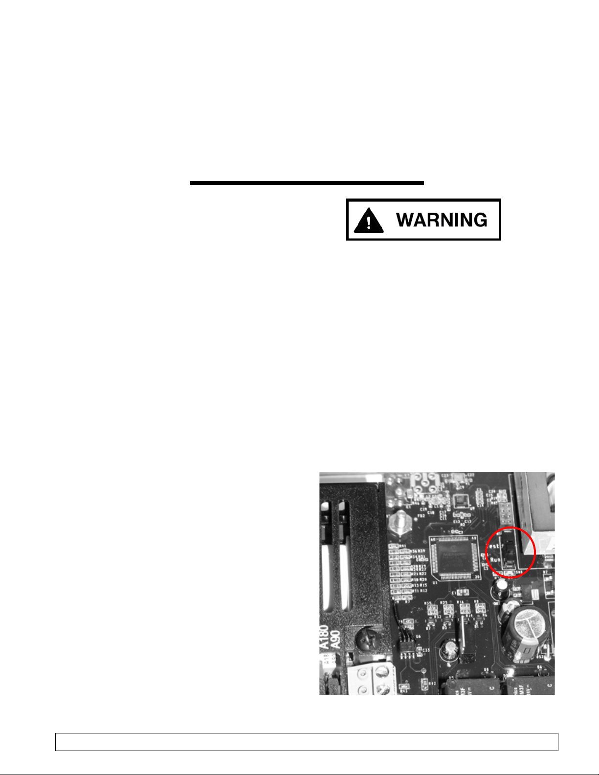
To aid in visual maintenance the drive can be placed in
“pulse mode” which will activate the unit and start the
rotation of the round belt for inspection. The unit will
start on and off to provide time to inspect the belt as
it travels the system. To activate the pulse inspection
system, you must open the control panel and toggle
the black switch inside to the position (Fig. 30).
Once the inspection of the belt is complete return to
the position.
Fig. 30
The Tractelift™ Type II has to be maintained/inspected
by a competent person, either on demand, or at the latest
after 12 months. The result of the annual inspection
has to be led in the log-book, included in the operation
manual.
are on principle main-
tenance-free.
a)
– for damage, oil loss, corrosion, dirt, in the con-
trolbox inltraded water, or impurities,
– of correct anchoring of bracket, xing plates, and
driver disk guard plate.
b)
regarding vibration and abnormal noise.
Stop the motor.
c) If the motor is , it should be cleaned to
ensure an effective air ow.
a)
– for damage, oil loss, corrosion, or dirt,
– of correct anchoring of bracket, xing plates, and
diverter disk guard plate.
b)
regarding vibration and abnormal noise.
Stop the motor.
The Climbing Aid is on principle maintenance-free.
During the annual safety inspection
resp. during intermediate service,
ex. in the course of “trouble-shooting”,
a competent person should check the installation according to
the following instructions
see chapter 4.2 on page 8.
Other manuals for Tractelift Type II
1
Table of contents
Other Tractel Construction Equipment manuals

Popular Construction Equipment manuals by other brands


Wacker Neuson
Wacker Neuson RD24 instruction manual

MULTILIFT
MULTILIFT Ultima S Flex User and maintenance manual

Doka
Doka Framax stripping corner I Series Original operating instructions

Hercules
Hercules G210 owner's manual

Marcegaglia Buildtech
Marcegaglia Buildtech N2BL-MARC2013 installation manual

Bomag
Bomag BW 900-2 operating instructions


