Tractel Griphoist Skybeam User manual
1
© 2013 Tractel Ltd. All Rights Reserved.
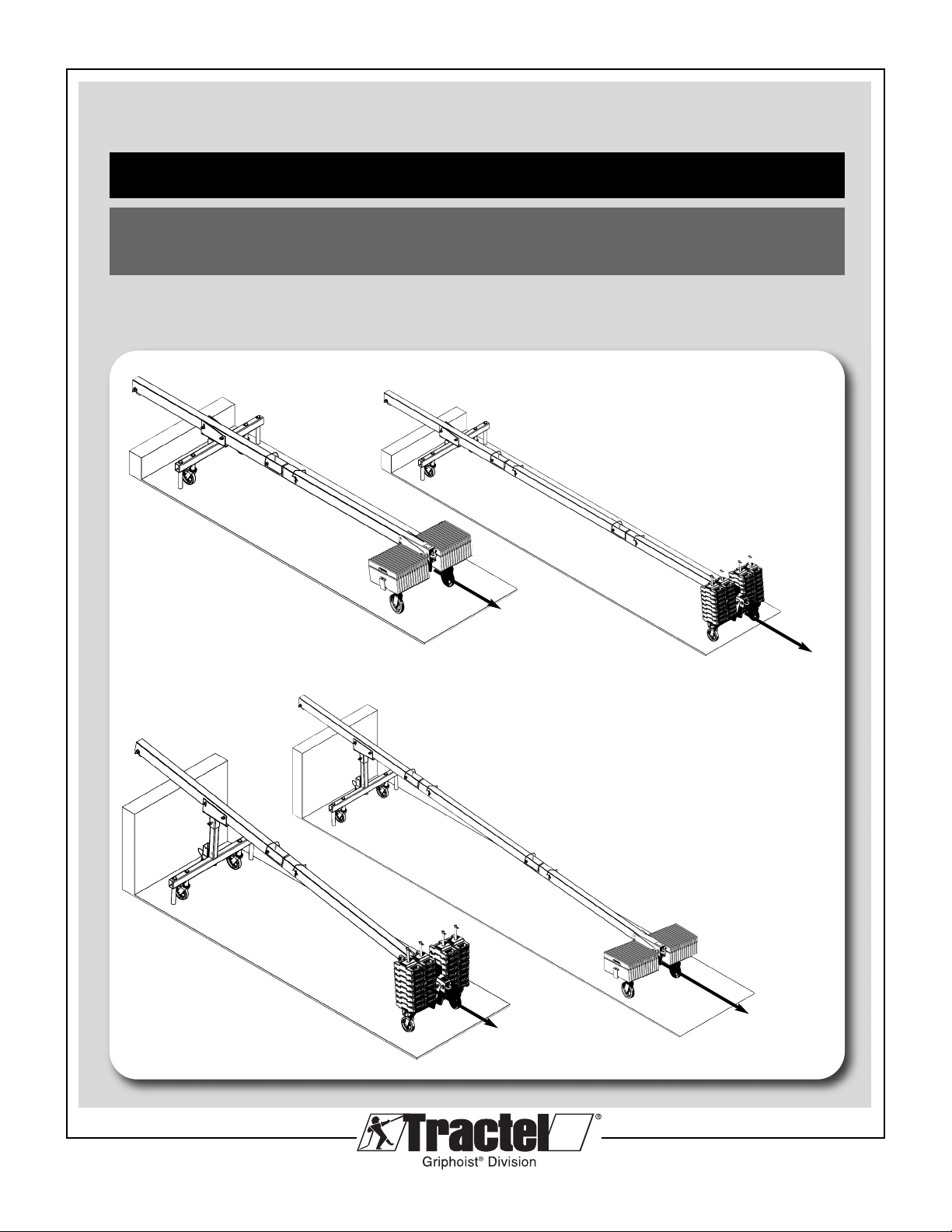
4’ reach light skybeam® 1,000 lb. (454kg) capacity
United States: Boston: 1 800 421-0246 • Los Angeles: 1 800 675-6727 • [email protected]
Canada: Montreal: 1 800 561-3229 • Toronto: 1 800 561-3229 • [email protected]
temporary outrigger beam for suspended platforms
assembly manual for
ractel, Griphoist®Division
4’ orizontal Beam
4’ Inclined Beam
Tieback
Required
Tieback
Required
Tieback
Required
Tieback
Required

© 2013 Tractel Ltd. All Rights Reserved.
2
CONTENTS
PAGE
1. GENERAL WARNING 4
2. TRANSPORT AND ANDLING 5
3. TEC NICAL SPECIFICATIONS OF T E 4’ SKYBEAM 6-9
3.1 Horizontal Version
3.2 Inclined Version
4. ASSEMBLY INSTRUCTIONS OF T E 4’ SKYBEAM 9-15
5. ASSEMBLY INSTRUCTIONS OT ER 16-19
5.1 Installation of Tieback
5.2 Calculation of Counterweights skybeams (reference)
5.3 Set up of Primary Wire Ropes
5.4 Set up of Outriggers and Counterweights
6. C ECKS BEFORE USING T E SKYBEAM 20
6.1 Suspension Points and Support Equipment
6.2 Tieback
6.3 Platforms
6.4 Wire Ropes
6.5 Hoists
7. USE AND OPERATION OF T E SKYBEAM 21
8. INFORMATION FOR MAINTENANCE 21
9. SKYBEAM LABELS AND MARKINGS 22-23
4’ reach light skybeam® 1,000 lb. (454kg) capacity
temporary outrigger beam for suspended platforms
assembly and operating instructions
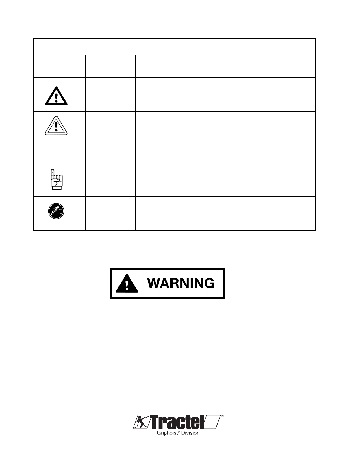
Explanation of Symbols used in this manual
Safety advice
Possible consequence
Symbol Code word Meanin of non-compliance
IMMEDIATE or
WARNING possibly imminent Fatal or serious injuries!
dan er:
CAUTION possibly dan erous Minor injuries to persons!
situation:
Other Advice
Statement of
NOTE Policy Related Dama e to equipment
to Safety: or its surroundin s
Instruction for
(none) documentation in writin (none)
(i.e. record keepin ):
© 2013 Tractel Ltd. All Rights Reserved.
3
The 4' reach light skybeam®is designed for a Maximum load of 1,000lbs (454kg).
Do not use this system with a hoist of a greater capacity then 1,000lbs (454kg).
© 2013 Tractel Ltd. All Rights Reserved.
4
GENERAL WARNING
Read this general warning first.
In suspended platform operations, safety is a matter of life or death for riggers,
operators and by-standers. This warning is your share of duties for achieving safety.
YOUR DUTY TO UNDERSTAND AND COMPLY.
1. It is the responsibility of the riggers and operators, and their
employer’s responsibility, if they operate under an
employer’s control, to strictly conform to the following
warnings.
2. It is imperative for safety and efficiency of operations
that this manual be read and fully understood by the
rigger and the operator before rigging or operating the
platform. All instructions contained herein must be
carefully and strictly followed, including applicable SAIA
code of safe practices.
3. Should you hand over a skybeam under any conditions, to
any party operating out of your control, you must attach a
clean copy of this manual and draw to other party’s attention
that strictly following all the instructions therein is a matter of
life or death.
4. Before using the skybeam, the rigger and the operator must
become aware of all the requirements of federal, state,
provincial and local safety regulations not only applicable to
the skybeam, but also to the entire suspended scaffold
system or any component of it.
5. Never use the skybeam for any job other than lifting
personnel on suspended scaffold according to the
instructions of this manual.
6. Never load the skybeam above its rated load.
YOUR DUTY TO INSPECT AND MAINTAIN.
7. Keep this manual available at all times for easy reference
whenever required. Extra copies are available through the
equipment supplier.
8. Carefully take notice of all the labels and markings affixed to
the skybeam. Never rig or operate the skybeam if any label,
normally fixed on it, is obscured or missing. Replacement
labels are available through the equipment supplier.
9. Every time the skybeam is to be rigged or used, check that
the skybeam, platform, hoists, wire ropes and other
components of the suspended scaffold system are complete
and in good working condition, prior to proceeding.
10. A careful and regular inspection of the platform hoists, wire
ropes and other components of the installation is part of the
safety requirements. If you have a question, call the
equipment supplier.
11. Before rigging, re-rigging and after, the skybeam must be
inspected by a Competent Person familiar with the skybeam
and professionally trained for the purpose.
12. Inspection by persons authorized by riphoist is to be
carried out once every six months, to spot check the
condition of the beam and its components and that
rigging is being done correctly. A signed and dated
report card should be maintained for these purposes.
13. The manufacturer declines any responsibility for
consequences of repairs or modifications brought out of
its control to the product, specially by replacement of
original parts or repairs by another manufacturer.
YOUR DUTY TO TRAIN AND CONTROL PEOPLE.
Compliance with safety rules extends to rigging
operations which must be carried out only after securing
safe conditions of operation as per safety regulations and
requirements.
14. An operator must not be assigned to a suspended job or
to rigging for a suspended job, or to de-rigging after the
job, if that person is not:
a) mentally and physically fit for the purpose, especially
at heights.
b) competent for the job to be performed.
c) familiar with the scaffold equipment as rigged.
d) professionally trained for working under the above
requirements.
Except for the operations described in this manual, the
maintenance of the skybeam, as well as repairs, must be
exclusively done by repairers authorized by riphoist.
Spare parts used for all equipment must be in
accordance with the product, no substitutions are
allowed.
15. Never let the skybeam or other components of a
suspended scaffold system be managed or operated by
any person other than authorized and assigned to the
job. Keep the equipment, either rigged or unrigged, out of
reach of unauthorized persons, while out of operation.
16. Training operators and riggers includes setting up rescue
procedure should a scaffold be brought to a standstill
during a job. Such procedure must be set up by a
Competent Person or its technical consultant, according
to the working conditions, prior to putting the equipment
into operation.
17. Every suspended job must be placed under the control of
a person having the required competence and authority
for checking that all the instructions prescribed by this
manual be regularly and efficiently carried out.
Draft #2 June 19, 2013

© 2013 Tractel Ltd. All Rights Reserved.
5
YOUR DUTY TO SAFETY BEYOND T E ROOFBEAM
As being only one piece of a scaffold system, the skybeam
can contribute to the required safety only if:
18. Compatibility of other brands has been verified & approved
by Tractel® griphoist engineering department.
19. It is fitted on compatible equipment.
20. Other components meet the requirements of the applicable
safety regulations and requirements, are of the proper
quality, assembled to form a safe and efficient suspended
scaffold system, and are approved by riphoist engineering
department.
21. Every upper support of the scaffold is stable, sufficiently
strong and properly tied back to the structure, according to
the load either static or dynamic.
22. The supporting structure and tie-backs are required to
withstand every load to be applied, either static or dynamic,
during rigging or operating the scaffold equipment.
23. All the requirements in strength and resistance are obtained
with the necessary safety coefficients (see regulations and
professional standards).
24. All the calculations, design and subsequent work necessary
to meet the above requirements have been made by a
Competent Person on the basis of proper technical
information regarding the site.
YOUR DUTY TO AVOID TAKING C ANCES.
25. Once the suspended platform has been lifted off its initial
support (ground or any other level), it is imperative not to
release, remove, alter or obstruct any part of the equipment
under load.
26. NEVER allow any condition which would result in a
suspension wire rope becoming SLACK during the
operation unless:
a) the suspended platform is safely supported on a safe
surface giving a safe access to the operator in compliance
with safety regulations.
b) another suspension wire rope has been safely rigged to
the suspension platform.
27. Never operate a platform and its accessories, especially
electric ones, in a potentially explosive atmosphere.
28. For any job to be performed on the suspended equipment,
consider and control the specific risks related to the nature
of the job.
29. Should you decide that this skybeam is no longer to be
used, take precautions in disposing of it so that it cannot be
used any more.
30. The manufacturer declines any responsibility for any
special rigging or structural combinations beyond the
descriptions of this manual.
31. The manufacturer declines any responsibility for any
other use of the skybeam, than described in this
manual.
32. Do not mix and match the 4' reach light skybeam and
the 11’ skybeam components. Only use configurations
as shown in this manual.
AN ULTIMATE RECOMMENDATION
Never neglect means to improve safety. Due to the risks
inherent in the use of suspended scaffolding, it is strongly
recommended that every installation be equipped with
secondary wire rope(s) fitted with a separate fall arrest
system, anchored to a safe separate point of the building
structure.
This manual is neither a regulations compliance
manual nor a general training guide on a suspended
scaffold operations. You must refer to proper
instructions delivered by manufacturers of the other
pieces of equipment included in your suspended
scaffold installation. Whenever calculations and
specific rigging and handling are involved, the operator
should be professionally trained to that end and secure
relevant information prior to commencing such work.
2. TRANSPORT AND ANDLING
andle equipment with care, do not drop equipment
during loading or unloading. Impose loads on the
skybeam gently and without impact.
© 2013 Tractel Ltd. All Rights Reserved.
6
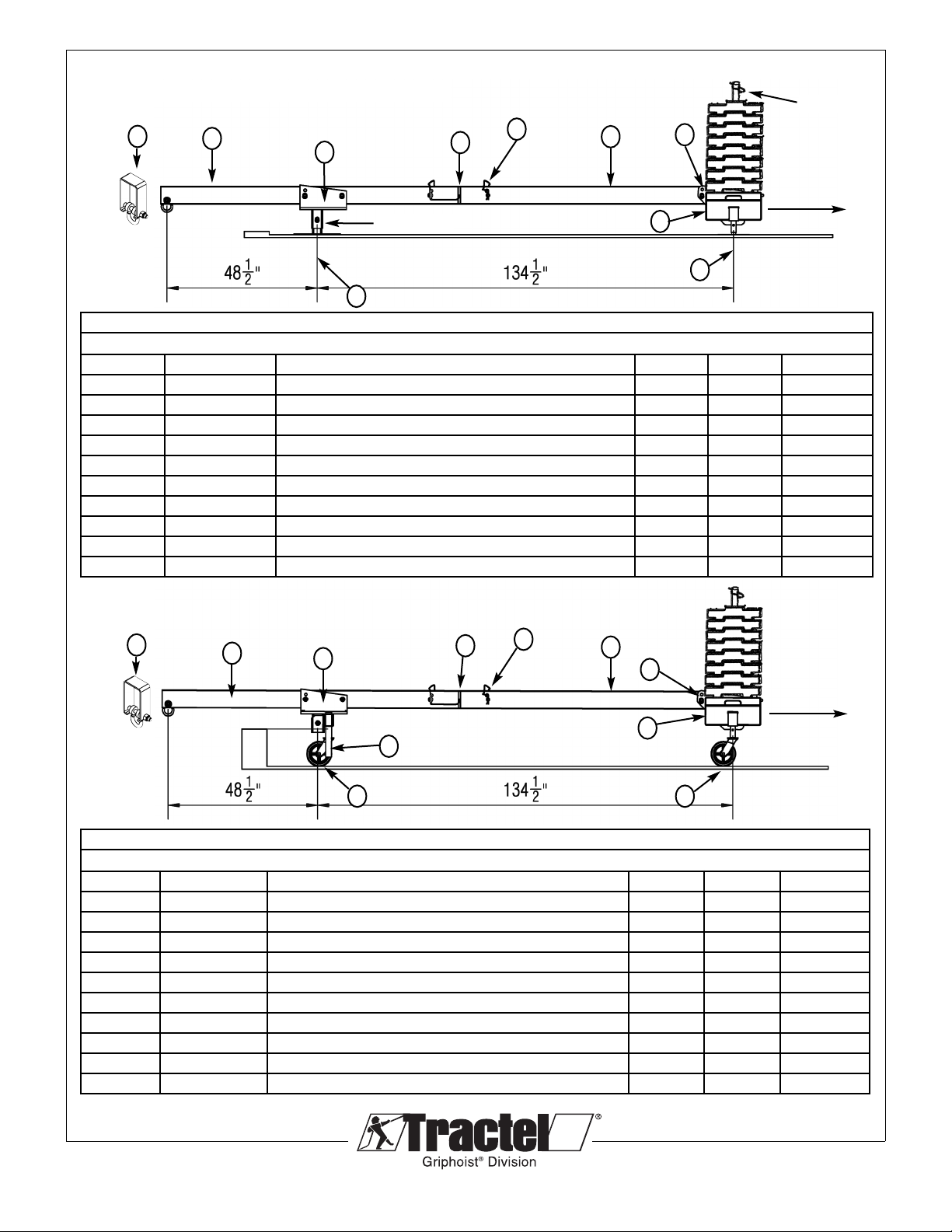
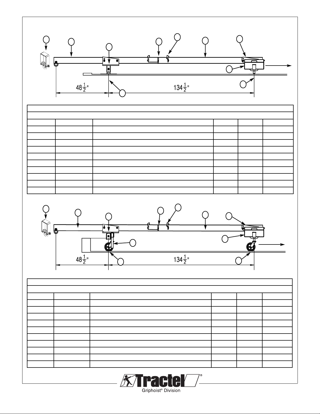
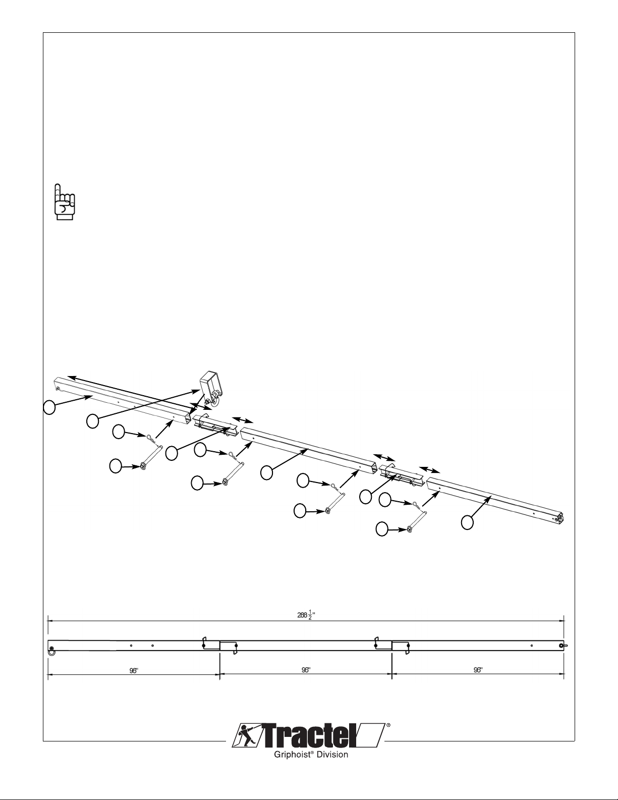
3.1 TEC NICAL SPECIFICATIONS AND COMPONENTS OF T E 4’ REAC LIG T ORIZONTAL SKYBEAM
ORIZONTAL 4' SKYBEAM - 4' REAC -1,000lb. (454 kg) CAPACITY - RBL0042
TWO 4' SECTION BEAMS WIT SINGLE COUNTERWEIG T FRAME ON PLATE STAND
ITEM PART # DESCRIPTION LB K QTY
1 RBC1010B FRONT SUPPORT SADDLE c/w 3 LOCK PINS 35 16 1
2 RBC2010 REAR SIN LE CWT FRAME c/w 2 LOCK PINS 60 28 1
3 RBH1080B REAR SUPPORT BASE PLATE c/w 2 MT BOLTS 84 2
4 RBC2070B FRONT SUPPORT BASE PLATE 29 13 1
5 RBLO210 FRONT 4 FOOT BEAM c/w SHACKLE 34.4 15.6 1
6 RBL0230 REAR 4 FOOT BEAM c/w SHACKLE 34.9 15.9 1
7 RBL0200 CONNECTION BEAM c/w 2 PINS 11.9 5.4 1
8 3378 COUNTERWEI HT - RIPHOIST (55 LB/25 K EACH) 55 25.0
28 by riphoist
9 RBL0910 OPTIONAL SLIDIN COLLAR 3.6 1.6 PARTS
10 RBC3080A LOCK PIN ASSEMBLY 3/4" DIA. c/w LANYARDS 10.5 PARTS
ORIZONTAL 4' SKYBEAM - 4' REAC -1,000lb. (454 kg) CAPACITY - RBL0040
TWO 4' SECTION BEAMS WIT SINGLE COUNTERWEIG T FRAME ON CASTORS
ITEM PART # DESCRIPTION LB K QTY
1 RBC1010B FRONT SUPPORT SADDLE c/w 3 LOCK PINS 35 16 1
2 RBC2010 REAR SIN LE CWT FRAME c/w 2 LOCK PINS 60 28 1
3 RBH1050B FRONT FRAME WITH SIDE HOLDER 24 11 1
4 RBL0210 FRONT 4 FOOT BEAM c/w SHACKLE 34.4 15.6 1
5 RBL0230 REAR 4 FOOT BEAM c/w SHACKLE 34.9 15.9 1
6 RBL0200 CONNECTION BEAM c/w 2 PINS 11.9 5.4 1
7 3378 COUNTERWEI HT - RIPHOIST (55 LB/25 K EACH) 55 25
28 by riphoist
8 HAC17W99 CASTER ASSEMBLY - RIPHOIST 13 6 4 by riphoist
9 RBL0910 OPTIONAL SLIDIN COLLAR 3.6 1.6 PARTS
10 RBC3080A LOCK PIN ASSEMBLY 3/4" DIA. c/w LANYARDS 10.5 PARTS
1
95
8
4
3
762
10
1
94
7
3
65
2
10
8
8
Tieback
Required
Tieback
Required
(Stacking weight version)
RBC2070B
RBC2010

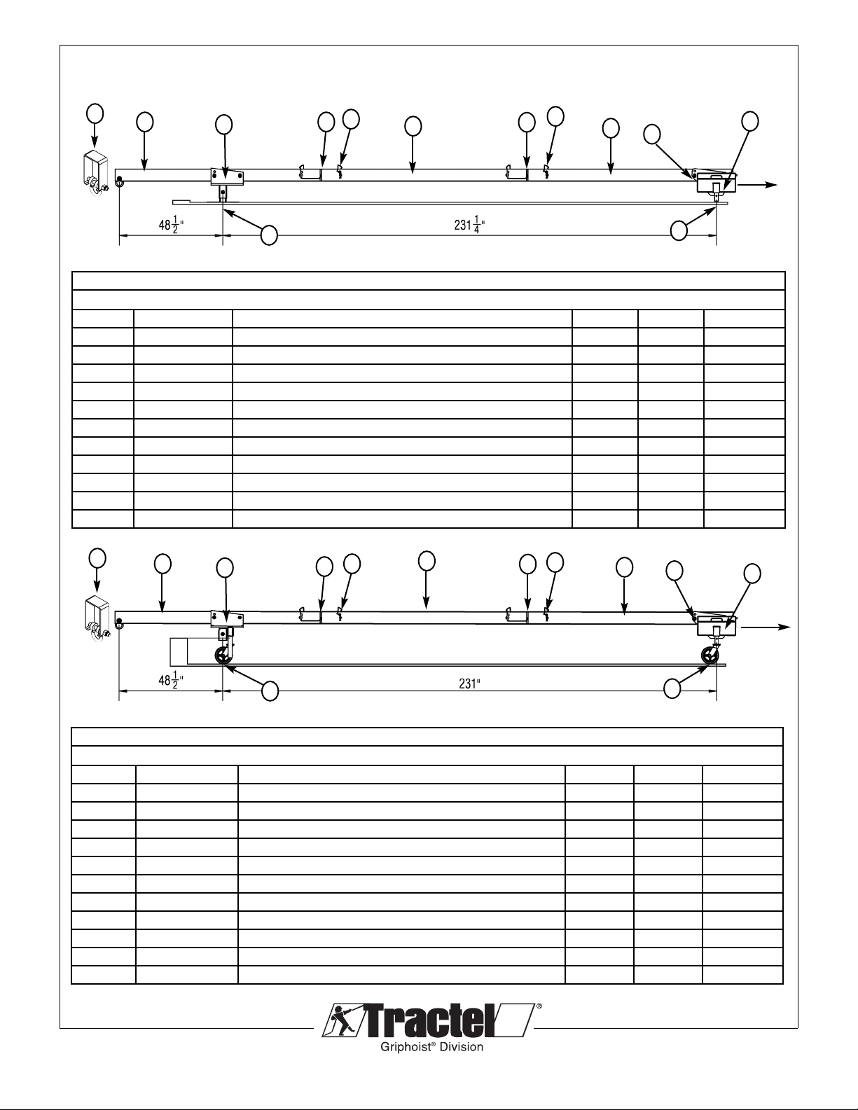
ORIZONTAL 4' SKYBEAM - 4' REAC -1,000lb. (454 kg) CAPACITY - RBL0043
T REE 4' SECTION BEAMS WIT SINGLE COUNTERWEIG T FRAME ON PLATE STAND
ITEM PART # DESCRIPTION LB K QTY
1 RBC1010B FRONT SUPPORT SADDLE c/w 3 LOCK PINS 35 16 1
2 RBC2010B REAR SIN LE CWT FRAME c/w 2 LOCK PINS 60 28 1
3 RBH1080B REAR SUPPORT BASE PLATE c/w 2 MT BOLTS 84 2
4 RBC2070B FRONT SUPPORT BASE PLATE 29 13 1
5 RBL0210 FRONT 4 FOOT BEAM c/w SHACKLE 34.4 15.6 1
6 RBL0230 REAR 4 FOOT BEAM c/w SHACKLE 34.9 15.9 1
7 RBL0220 MIDDLE 4 FOOT BEAM 32.2 14.6 1
8 RBL0200 CONNECTION BEAM c/w 2 PINS 11.9 5.4 2
9 3378 COUNTERWEI HT - RIPHOIST (55 LB/25 K EACH) 55 25.0
16 by riphoist
10 RBL0910 OPTIONAL SLIDIN COLLAR 3.6 1.6 PARTS
11 RBC3064A LOCK PIN ASSEMBLY 3/4" DIA. c/w LANYARDS 10.5 PARTS
© 2013 Tractel Ltd. All Rights Reserved.
7
3.1 TEC NICAL SPECIFICATIONS AND COMPONENTS OF T E 4’ REAC LIG T ORIZONTAL SKYBEAM
ORIZONTAL 4' SKYBEAM - 4' REAC -1,000lb. (454 kg) CAPACITY - RBL0041
T REE 4' SECTION BEAMS WIT SINGLE COUNTERWEIG T FRAME ON CASTORS
ITEM PART # DESCRIPTION LB K QTY
1 RBC1010B FRONT SUPPORT SADDLE c/w 3 LOCK PINS 35 16 1
2 RBC2010B REAR SIN LE CWT FRAME c/w 2 LOCK PINS 60 28 1
3 RBH1050B FRONT FRAME WITH SIDE HOLDER 24 11 1
4 RBL0210 FRONT 4 FOOT BEAM c/w SHACKLE 34.4 15.6 1
5 RBL0230 REAR 4 FOOT BEAM c/w SHACKLE 34.9 15.9 1
6 RBL0220 MIDDLE 4 FOOT BEAM 32.2 14.6 1
7 RBL0200 CONNECTION BEAM c/w 2 PINS 11.9 5.4 2
8 3378 COUNTERWEI HT - RIPHOIST (55 LB/25 K EACH) 55 25
16 by riphoist
9 HAC17W99 CASTER ASSEMBLY - RIPHOIST 13 6 4 by riphoist
10 RBL0910 OPTIONAL SLIDIN COLLAR 3.6 1.6 PARTS
11 RBC3080A LOCK PIN ASSEMBLY 3/4" DIA. c/w LANYARDS 10.5 PARTS
1
47
99
652
10 78
11
11
(Stacking weight version)
RBC2070B
1
58
43
762
10 89
11
11
Tieback
Required
Tieback
Required
© 2013 Tractel Ltd. All Rights Reserved.
8
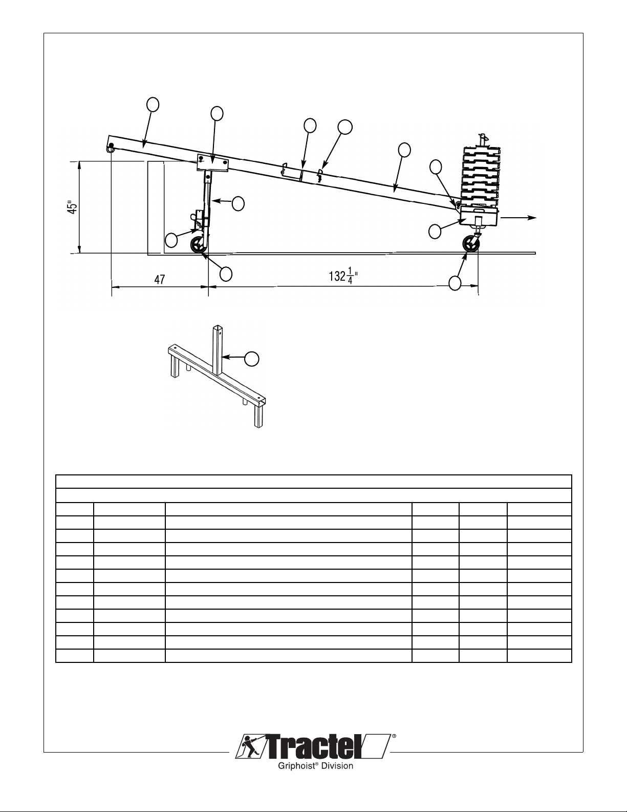
3.2
TEC NICAL SPECIFICATIONS AND COMPONENTS OF T E 4’ REAC LIG T ORIZONTAL SKYBEAM
6
2
1
4
3
7
5
INCLINED 4' SKYBEAM - 4' REAC -1,000lb. (454 kg) - RBL0030
TWO 4' SECTION BEAMS WIT SINGLE COUNTERWEIG T FRAME ON CASTORS
ITEM PART # DESCRIPTION LB K QTY
1 RBC1010B FRONT SUPPORT SADDLE c/w 3 LOCK PINS 35 16 1
2 RBC2010B REAR SIN LE CWT FRAME c/w 2 LOCK PINS 60 28 1
3 RBI1016A FRONT VERTICAL TUBE c/w 1 LOCK PIN 22 10 1
4 RBH1050B FRONT FRAME WITH SIDE HOLDER 24 11 1
5 RBL0210 FRONT 4 FOOT BEAM c/w SHACKLE 34.4 15.6 1
6 RBL0230 REAR 4 FOOT BEAM c/w SHACKLE 34.9 15.9 1
7 RBL0200 CONNECTION BEAM c/w 2 PINS 11.9 5.4 1
8 3378 COUNTERWEI HT - RIPHOIST (55 LB/25 K EACH) 55 25 28 by riphoist
9 HAC17W99 CASTER ASSEMBLY - RIPHOIST 13 6 4 by riphoist
10 RBI1070B FRONT FRAME 100 45 OPTION
11 RBC3080A LOCK PIN ASSEMBLY 3/4" DIA. c/w LANYARDS 10.5 PARTS
11
10
9
9
8Tieback
Required

© 2013 Tractel Ltd. All Rights Reserved.
9
3.2
TEC NICAL SPECIFICATIONS AND COMPONENTS OF T E 4’ REAC LIG T ORIZONTAL SKYBEAM
INCLINED 4' SKYBEAM - 4' REAC -1,000lb. (454 kg) - RBL0031
T REE 4' SECTION BEAMS WIT SINGLE COUNTERWEIG T FRAME ON CASTORS
ITEM PART # DESCRIPTION LB K QTY
1 RBC1010B FRONT SUPPORT SADDLE c/w 3 LOCK PINS 35 16 1
2 RBC2010B REAR SIN LE CWT FRAME c/w 2 LOCK PINS 60 28 1
3 RBI1016A FRONT VERTICAL TUBE c/w 1 LOCK PIN 22 10 1
4 RBH1050B FRONT FRAME WITH SIDE HOLDER 24 11 1
5 RBL0210 FRONT 4 FOOT BEAM c/w SHACKLE 34.4 15.6 1
6 RBL0230 REAR 4 FOOT BEAM c/w SHACKLE 34.9 15.9 1
7 RBL0220 MIDDLE 4 FOOT BEAM 32.2 14.6 1
8 RBL0200 CONNECTION BEAM c/w 2 PINS 11.9 5.4 2
9 3378 COUNTERWEI HT - RIPHOIST (55 LB/25 K EACH) 55 25 16 by riphoist
10 HAC17W99 CASTER ASSEMBLY - RIPHOIST 13 6 4 by riphoist
11 RBI1070B FRONT FRAME 100 45 OPTION
12 RBC3080A LOCK PIN ASSEMBLY 3/4" DIA. c/w LANYARDS 10.5 PARTS
6
2
1
4
3
7
5
12
11
9
8
8
12
10
11
Tieback
Required
© 2013 Tractel Ltd. All Rights Reserved.
10
3.3 TEC NICAL SPECIFICATIONS AND COMPONENTS OF T E 4’ REAC LIG T ORIZONTAL SKYBEAM
ORIZONTAL 4' SKYBEAM - 4' REAC -1,000lb. (454 kg) CAPACITY - RBL0022
TWO 4' SECTION BEAMS WIT SINGLE COUNTERWEIG T FRAME ON PLATE STAND
ITEM PART # DESCRIPTION LB K QTY
1 RBC1010B FRONT SUPPORT SADDLE c/w 3 LOCK PINS 35 16 1
2 RBC2010 REAR SIN LE CWT FRAME c/w 2 LOCK PINS 60 28 1
3 RBH1080B REAR SUPPORT BASE PLATE c/w 2 MT BOLTS 84 2
4 RBC2070B FRONT SUPPORT BASE PLATE 29 13 1
5 RBLO210 FRONT 4 FOOT BEAM c/w SHACKLE 34.4 15.6 1
6 RBL0230 REAR 4 FOOT BEAM c/w SHACKLE 34.9 15.9 1
7 RBL0200 CONNECTION BEAM c/w 2 PINS 11.9 5.4 1
8 3378 COUNTERWEI HT - RIPHOIST (55 LB/25 K EACH) 55 25.0
28 by riphoist
9 RBL0910 OPTIONAL SLIDIN COLLAR 3.6 1.6 PARTS
10 RBC3080A LOCK PIN ASSEMBLY 3/4" DIA. c/w LANYARDS 10.5 PARTS
ORIZONTAL 4' SKYBEAM - 4' REAC -1,000lb. (454 kg) CAPACITY - RBL0020
TWO 4' SECTION BEAMS WIT SINGLE COUNTERWEIG T FRAME ON CASTORS
ITEM PART # DESCRIPTION LB K QTY
1 RBC1010B FRONT SUPPORT SADDLE c/w 3 LOCK PINS 35 16 1
2 RBC2010 REAR SIN LE CWT FRAME c/w 2 LOCK PINS 60 28 1
3 RBH1050B FRONT FRAME WITH SIDE HOLDER 24 11 1
4 RBL0210 FRONT 4 FOOT BEAM c/w SHACKLE 34.4 15.6 1
5 RBL0230 REAR 4 FOOT BEAM c/w SHACKLE 34.9 15.9 1
6 RBL0200 CONNECTION BEAM c/w 2 PINS 11.9 5.4 1
7 3378 COUNTERWEI HT - RIPHOIST (55 LB/25 K EACH) 55 25
28 by riphoist
8 HAC17W99 CASTER ASSEMBLY - RIPHOIST 13 6 4 by riphoist
9 RBL0910 OPTIONAL SLIDIN COLLAR 3.6 1.6 PARTS
10 RBC3080A LOCK PIN ASSEMBLY 3/4" DIA. c/w LANYARDS 10.5 PARTS
1
95
8
4
3
762
10
1
94
7
3
652
10
8
8
Tieback
Required
Tieback
Required
(Sliding weight version)
© 2013 Tractel Ltd. All Rights Reserved.
11
ORIZONTAL 4' SKYBEAM - 4' REAC -1,000lb. (454 kg) CAPACITY - RBL0023
T REE 4' SECTION BEAMS WIT SINGLE COUNTERWEIG T FRAME ON PLATE STAND
ITEM PART # DESCRIPTION LB K QTY
1 RBC1010B FRONT SUPPORT SADDLE c/w 3 LOCK PINS 35 16 1
2 RBC2010B REAR SIN LE CWT FRAME c/w 2 LOCK PINS 60 28 1
3 RBH1080B REAR SUPPORT BASE PLATE c/w 2 MT BOLTS 84 2
4 RBC2070B FRONT SUPPORT BASE PLATE 29 13 1
5 RBL0210 FRONT 4 FOOT BEAM c/w SHACKLE 34.4 15.6 1
6 RBL0230 REAR 4 FOOT BEAM c/w SHACKLE 34.9 15.9 1
7 RBL0220 MIDDLE 4 FOOT BEAM 32.2 14.6 1
8 RBL0200 CONNECTION BEAM c/w 2 PINS 11.9 5.4 2
9 3378 COUNTERWEI HT - RIPHOIST (55 LB/25 K EACH) 55 25.0
16 by riphoist
10 RBL0910 OPTIONAL SLIDIN COLLAR 3.6 1.6 PARTS
11 RBC3064A LOCK PIN ASSEMBLY 3/4" DIA. c/w LANYARDS 10.5 PARTS
3.3 TEC NICAL SPECIFICATIONS AND COMPONENTS OF T E 4’ REAC LIG T ORIZONTAL SKYBEAM
ORIZONTAL 4' SKYBEAM - 4' REAC -1,000lb. (454 kg) CAPACITY - RBL0021
T REE 4' SECTION BEAMS WIT SINGLE COUNTERWEIG T FRAME ON CASTORS
ITEM PART # DESCRIPTION LB K QTY
1 RBC1010B FRONT SUPPORT SADDLE c/w 3 LOCK PINS 35 16 1
2 RBC2010B REAR SIN LE CWT FRAME c/w 2 LOCK PINS 60 28 1
3 RBH1050B FRONT FRAME WITH SIDE HOLDER 24 11 1
4 RBL0210 FRONT 4 FOOT BEAM c/w SHACKLE 34.4 15.6 1
5 RBL0230 REAR 4 FOOT BEAM c/w SHACKLE 34.9 15.9 1
6 RBL0220 MIDDLE 4 FOOT BEAM 32.2 14.6 1
7 RBL0200 CONNECTION BEAM c/w 2 PINS 11.9 5.4 2
8 3378 COUNTERWEI HT - RIPHOIST (55 LB/25 K EACH) 55 25
16 by riphoist
9 HAC17W99 CASTER ASSEMBLY - RIPHOIST 13 6 4 by riphoist
10 RBL0910 OPTIONAL SLIDIN COLLAR 3.6 1.6 PARTS
11 RBC3080A LOCK PIN ASSEMBLY 3/4" DIA. c/w LANYARDS 10.5 PARTS
1
47
99
652
10 78
11
11
(Sliding weight version)
1
5 8
43
762
10 89
11
11
Tieback
Required
Tieback
Required
4.1 ASSEMBLY OF T E 4’ SKYBEAM®
The SKYBEAM must be pre-assembled in accordance with
these instructions. The counterweights are assembled on the
counterweight Frame and all roof loads must be confirmed in
accordance with this manual.
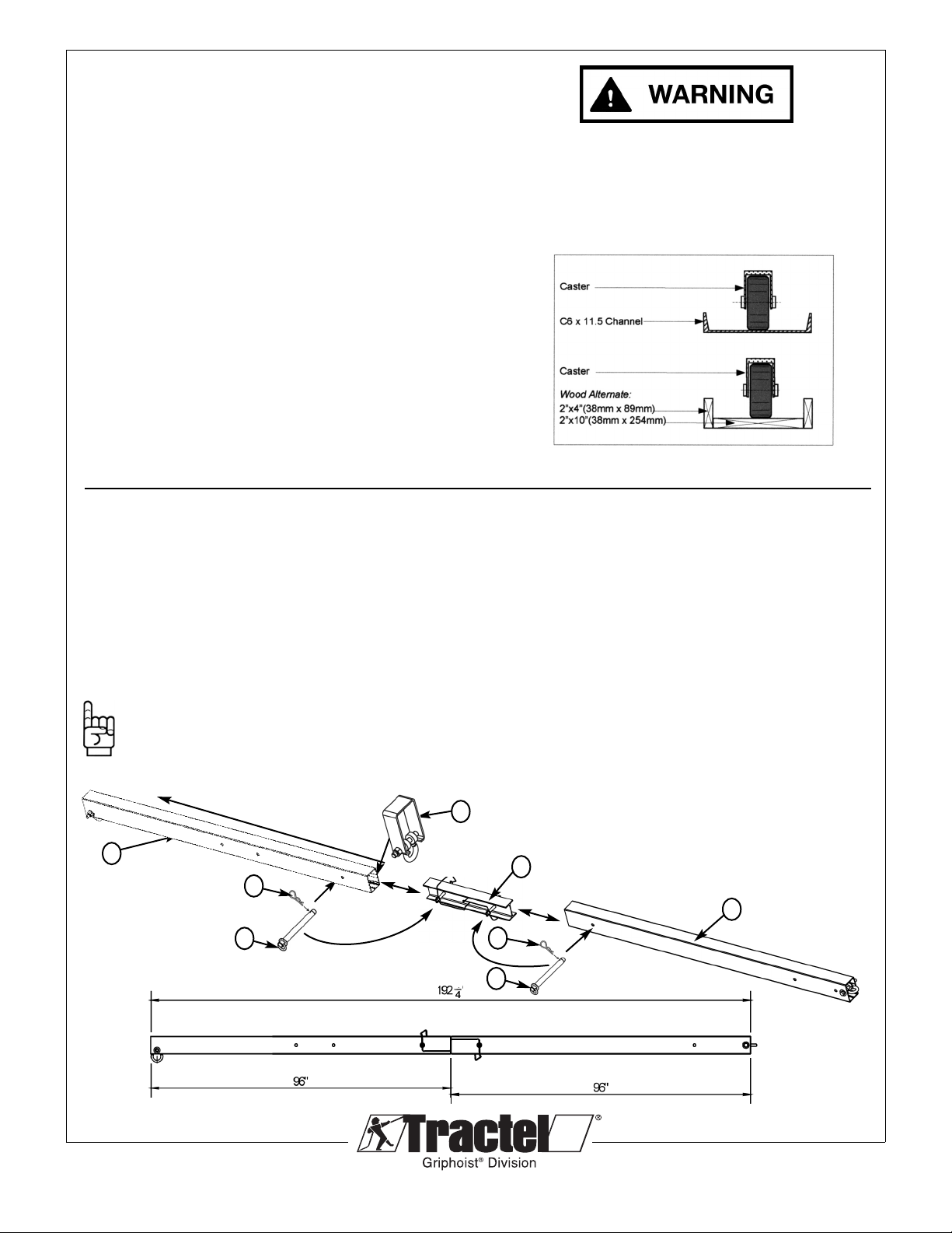
When using casters, install guide channels on structure to guide
the casters. Two channels are required, one for the front
support and one for the rear counterweight Frame. See Fig. 1.
• Block the end of guide channels with end stops.
• Always use a guide channel on roofs to distribute bearing
load.
• uide channels to run parallel to building face.
• Rigidly secure both ends of guide channels to the structure
Determine if you are using the two or three beam version of the
4’ Skybeam. Both have a 4’ reach and a 1,000lb (454 kg)
capacity, the advantage of the three piece beam is less
counterweights are required (16) versus (28) required for the
two beam variation.
4.2 TWO PIECE SKYBEAM ASSEMBLY. (MRB2P)
Ensure you have the correct components for assembly
1 – MRBL0200 Connection Beam (1)
1 – MRBL0210 4’ Front Beam (2)
1 – MRBL0230 4’ Rear Beam (3)
Lie the components on the ground in the following sequence:
Front beam (2) – Connection Beam (1) – Rear Beam (3)
Note: If Using the Optional Sliding Collar (for Horizontal
applications only) (4), slide the collar onto the bottom of
the Front Beam (2) before connecting the unit together.
Then slide the collar behind the front shackle.
© 2012 Tractel Ltd. All Rights Reserved.
12
Fig. 1
3
When using casters, channel guides or
roofjacks must be used.
1) Slide the connection beam (1) into the back of the front
beam (2) to so the first hole aligns with the back hole of
the front beam as shown in Fig 2. Connect the beams
together with the provided 3/4" locking pin (5) and secure
the locking pin with the hair pin (6) provided.
2) The rear beam (3) is then slide over the remaining
section of the connection beam and joined at the front
hole of the rear beam as shown Fig. 2. Connect the
beams together with the provided 3/4" locking pin (5) and
secure the locking pin with the hair pin (6) provided.
For Assembly in the horizontal position go to section 4.4,
for the inclined position go to section 4.5.
1
2
5
5
6
6
4
Fig. 2
Fig. 3
4.3 T REE PIECE SKYBEAM ASSEMBLY. (MRB3P)
Ensure you have the correct components for assembly
2 – MRBL0200 Connection Beam (1)
1 – MRBL0210 4’ Front Beam (2)
1 – MRBL0220 4’ Middle Beam (3)
1 – MRBL0230 4’ Rear Beam (4)
Lie the components on the ground in the following sequence:
Front beam (2) – Connection Beam (1) – Middle Beam (3) -
Connection Beam (1) – Rear Beam (4)
Note: If Using the Optional Sliding Collar (for Horizontal
applications only) (7), slide the collar onto the bottom of
the Front Beam (2) before connecting the unit together.
Then slide the collar behind the front shackle.
1) Slide the connection beam (1) into the back of the front beam
(2) to so the first hole aligns with the back hole of the front
beam as shown in Fig 3. Connect the beams together with the
provided 3/4" locking pin (5) and secure the locking pin with the
hair pin (6) provided.
© 2013 Tractel Ltd. All Rights Reserved.
13
2) The middle beam (3) then slides over the remaining
section of the connection beam and joined at the front
hole of the middle beam as shown Fig. 4. Connect the
beams together with the provided 3/4" locking pin (5) and
secure the locking pin with the hair pin (6) provided.
3) Slide the connection beam (1) into the back of the
middle beam (3) to so the first hole aligns with the back
hole of the middle beam as shown in Fig 5. Connect the
beams together with the provided 3/4" locking pin (5) and
secure the locking pin with the hair pin (6) provided.
4) The rear beam (4) is then slides over the remaining
section of the connection beam and joined at the front
hole of the rear beam as shown Fig. 6. Connect the
beams together with the provided 3/4" locking pin (5) and
secure the locking pin with the hair pin (6) provided.
For Assembly in the horizontal position go to section 4.4,
for the inclined position go to section 4.5.
3
1
2
5
6
7
1
4
5
6
5
6
5
6
Fig. 4
Fig. 5
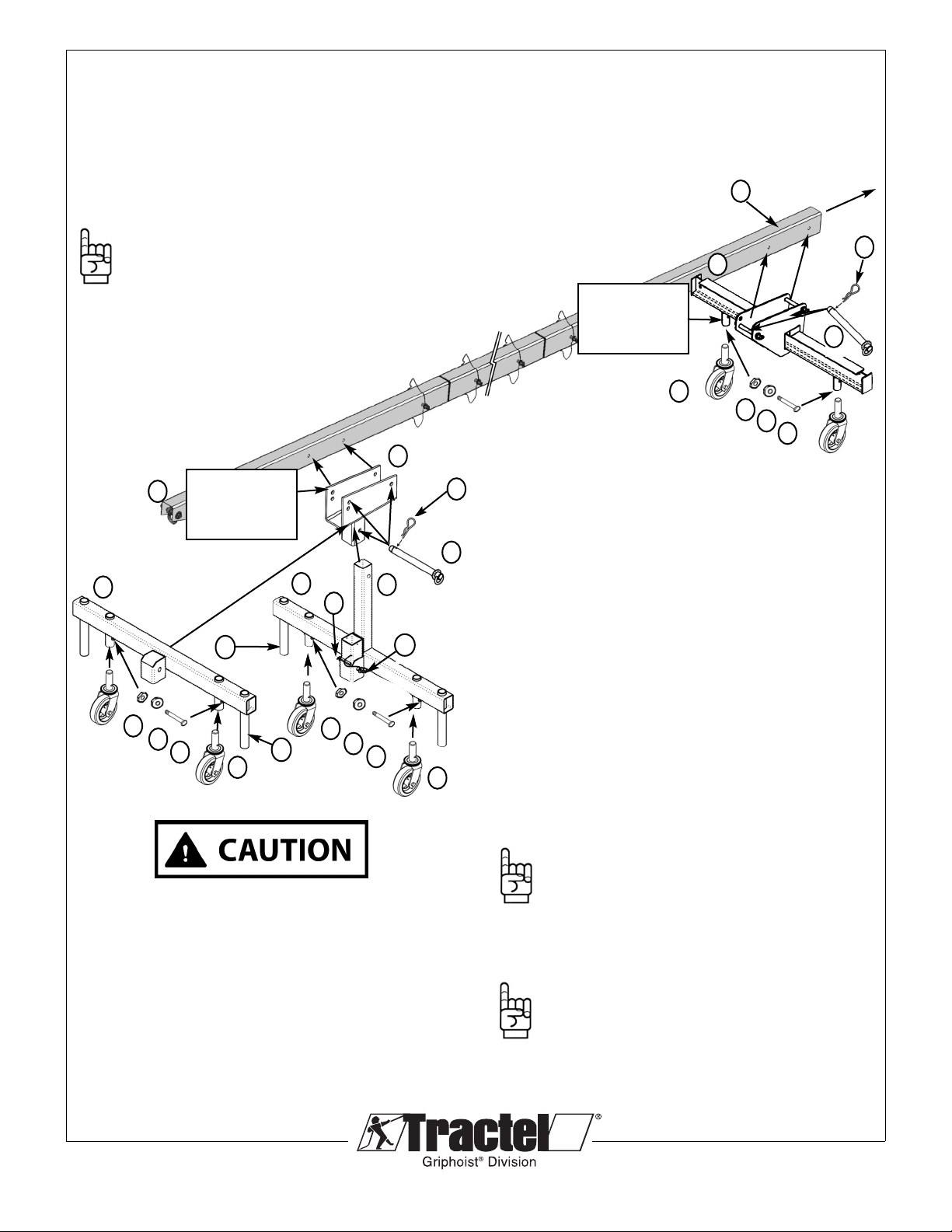
4.4 CONTINUED - ASSEMBLY OF 4’ ROOF BEAM -
INCLINED VERSION (Two or three piece beam)
FRONT FRAME
Set the reach and connect the front support (1) to the front
beam (2) with two 3/4" dia. locking pins (3) onto the ‘U’ shaped
Top Ledger of the front support, through aligned holes* on the
frame and beam. Be sure to lock the pins with the hair pins (4)
provided. When attaching the front support (1) ensure you do
not exceed the maximum extension of the front beam (2)
based on your load weight calculations.
*Note: The front support (1) has three holes in total,
always face the side with two holes toward the front of
the beam. These two holes are dependent on the
configuration being used. The top is used when
the beam configuration is for inclined position
and the bottom used for the
horizontal position.
INCLINED BEAM
Attach casters (5) to the front leg (6) by aligning holes in the
leg with those of the casters and connect with the 0.375" bolt
(7), washer (8) and nut (9). Then slip the front leg into the front
support and align the holes and connect using a 3/4” locking
pin (3) and secure with the hair pin (4).
For bigger loads/reaches than 1000lbs. /5 Ft. use wood
plates under the two vertical extensions (10) of the
inclined front support, to unload the wheels.
ORIZONTAL BEAM
Attach the front support (1) to the front leg (11) by slipping the
Leg into the front support and aligning the holes and connect
using the 3/4” locking pin (3) and secure with the hair pin (4).
COUNTERWEIG T BEAM
The counterweight beam (12) is secured with two 3/4" dia.
locking pins (13) into the ‘U’ shaped center ledge of the rear
beam (14), through aligned holes** on the frame and the tail
end of the beam. Be sure to lock the pins with the hair pins
provided (15). See Fig. 5
Note: The casters are already attached to the
counterweight beam.
**Note: The counterweight beam (12) has three holes
in total, always face the side with two holes toward the
front of the beam.These two holes are dependent on
the configuration being used. The top is used when
the beam configuration is for inclined position and the
bottom used for the horizontal position.
© 2012 Tractel Ltd. All Rights Reserved.
14
6
2
8
5
1
7
14
12
3
9
Fig. 6
Tieback
Required
11
4
10
13
15
Use the top hole for
the reclined position
Use the top hole for
the reclined position
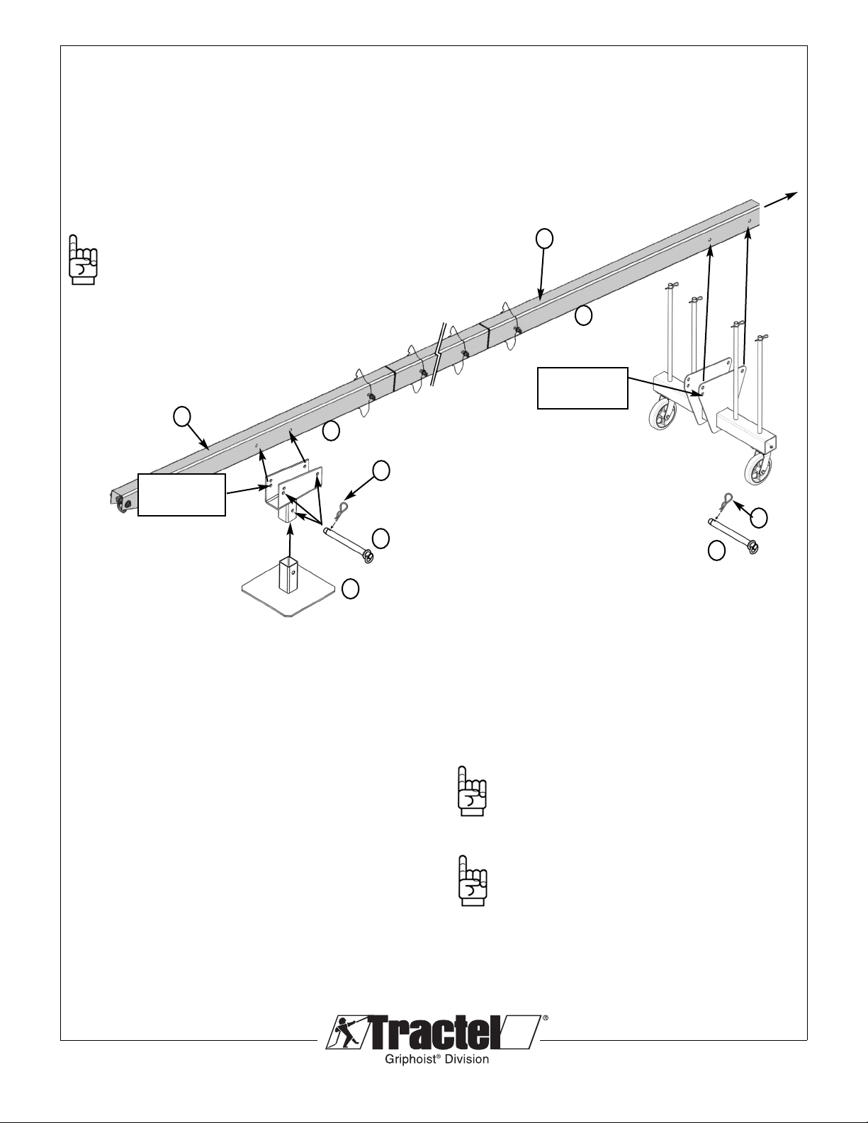
4.4 CONTINUED - ASSEMBLY OF ROOF BEAM -
ORIZONTAL VERSION (TWO OR T REE PIECE
BEAM)
FRONT SUPPORT
Connect the Front Support (1) to the Front Beam (2) with two
3/4" dia. Locking Pins (3) using the ‘U’ shaped form of the Front
Support, through aligned holes* on the support and beam. Be
sure to lock the pins with the hair Pins (4) provided.
*Note: The Front Support (1) has three sets of holes in
total. Always face the side with two holes toward the front
of the beam. These two holes are dependent on the
configuration being used. The top is used when the
beam configuration is for inclined position and the bottom
used for the horizontal position.
Installing the orizontal Front Support Base Plate
Attach the Front Support (1) to the Support Base Plate (11) by
slipping the leg into the Front Support and aligning the holes
and connect using the 3/4” Locking Pin (3) and secure with the
Hair Pin (4).
© 2012 Tractel Ltd. All Rights Reserved.
15
COUNTERWEIG T BEAM
The counterweight beam (12) is secured with two 3/4" dia.
locking pins (13) into the ‘U’ shaped center ledge of the rear
beam (14), through aligned holes** on the frame and the tail
end of the beam. Be sure to lock the pins with the hair pins
provided (15). See Fig. 5
Note: The casters are already attached to the
counterweight beam.
**Note: The counterweight beam (12) has three holes
in total, always face the side with two holes toward
the front of the beam.These two holes are dependent
on the configuration being used. The top is used
when the beam configuration is for inclined position
and the bottom used for the horizontal position.
2
1
14
4
11
3
12
Fig. 7
Use the bottom
hole for the
horizontal position
Use the bottom
hole for the
horizontal position
Tieback
Required
13
15
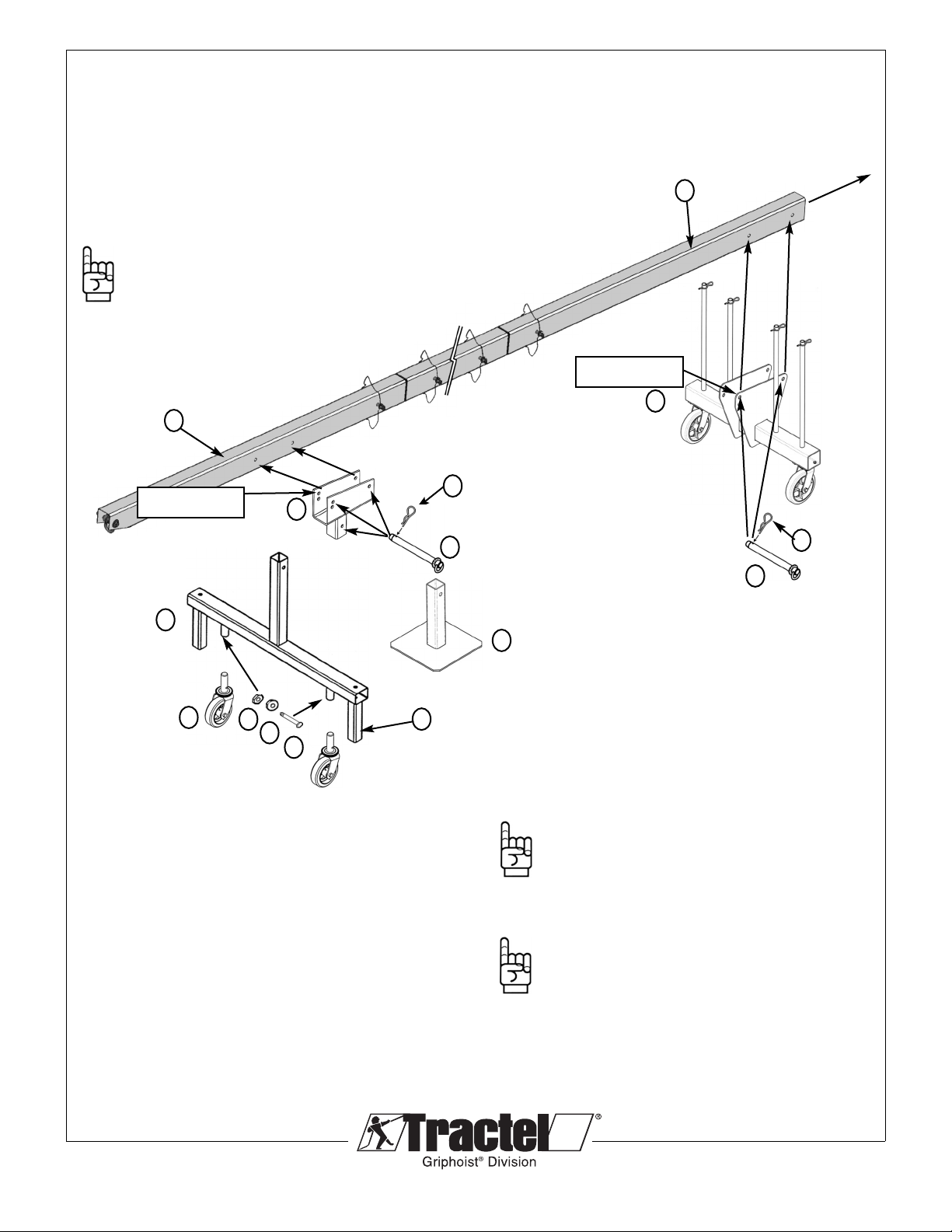
4.4 CONTINUED - ASSEMBLY OF 4 ROOF BEAM -
ADJUSTABLE STAND (RBI101016A & RB 1050B)
FRONT SUPPORT
Connect the front support (1) to the Front Beam (2) with two
3/4" dia. Locking Pins (3) using the ‘U’ shaped form of the front
support, through aligned holes* on the support and beam. Be
sure to lock the pins with the Hair Pins (4) provided.
*Note: The Front Support (1) has three sets of holes in
total. Always face the side with two holes toward the
front of the beam. These two holes are dependent on
the configuration being used. The top is used when the
beam configuration is for inclined position and the
bottom used for the horizontal position.
It is recommended to use wood plates or roofjacks
with the two vertical extensions (11) of the inclined
high support to unload the casters.
Installing Adjustable Stand for orizontal or Inclined
positioning of the Roofbeam
Attach casters (5) to the Front Frame (7) by aligning holes in the
legs with those of the casters and connect with the 3/8" bolt (8),
washer (9) and nut (10). For the Horizontal position the front
support (1) into the front frame (7) in the center post support and
align the holes and connect using a 3/4” locking pin (3) and secure
with the hair pin (4).
SINGLE COUNTERWEIG T FRAMES
Single Counterweight Frame (13) is secured with two 3/4"
dia. Locking Pins (3) into the back of the Rear Beam (14),
through aligned holes** on the Counterweight Frame and the
tail end of the beam. Be sure to lock the pins with the hair
pins provided (4).
See Fig. 8.
**Note: The Counterweight Frames (13) have three sets of
holes in total. Always face the side with two holes
toward the front of the beam. These two holes are
dependent on the configuration being used. The top
is used when the beam configuration is for inclined
position and the bottom is used for the horizontal
position.
Note: Installation of casters if not already in place. Attach
casters (5) to the Single Counterweight Frame (13) by
aligning holes in the bottom posts on the
Counterweight Frame with those of the casters and
connect with the 3/8" bolt (8), washer (9) and nut (10).
Two casters are required for the Single Counterweight
Frame.
© 2012 Tractel Ltd. All Rights Reserved.
16
2
9
5
1
8
7
14
4
3
10
13
3
4
Fig. 8.
10 98
Use the top hole for
the inclined position
and the bottom hole
for the horizontal
position.
Use the top hole for
the inclined position
and the bottom hole
for the horizontal
position.
5
98
10
11
11
76
5
3
4
For the inclined position install the inclined extension (6) into the
front frame (7) as shown and connect using a 3/4” locking pin
(3) and secure with the hair pin (4). The inclined extension is
then inserted into the front support (1) and connected using the
3/4” locking pin (3) and secured with the hair pin (4).
Tieback
Required
© 2012 Tractel Ltd. All Rights Reserved.
17
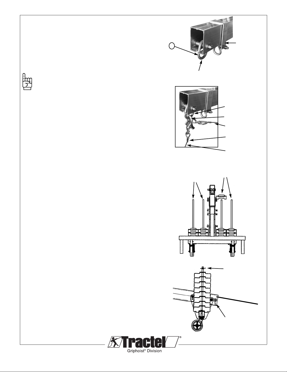
4.4 CONTINUED - ASSEMBLY OF ROOF BEAM
Level the outrigger beam and support assembly. Attach the
thimble end of the suspension wire rope to beam using a 5/8",
3-1/4 ton shackle (1). See Fig 10. Once the rope is attached,
set the assembly into working position. For beams with casters,
apply the brakes on all of the casters. Once in position install
taut tieback to the rear shackle (Fig. 13) as shown on Page 16
& 17 Fig. 14 & 15.
Note: The optional sliding collar shown in Fig. 10 is
for suspension only in the horizontal position. It is
not recommended for the inclined suspension beam.
If you are using the two beam version of the 4’
skybeam 28 counterweights are required. The three
beam version requires 16 counterweights. Both
beams have a 4’ reach and a 1,000lb. (454 kg)
maximum capacity.
Add the counterweights (#3348) (up to 32 max.) to the
counterweight beam (See fig 8). Check once again the
maximum admissible load (see Section 4.4 page 17 –
Calculation of counterweight) related to the reach and the
number of counterweights on the counterweight beam. Install all
required counterweights on the counterweight beam by lowering
them over the extension pole, starting with the two inside poles.
Distribute the weight as equally as possible on each side of the
frame. See Fig.12.
When all weights are in place install the locking pin to prevent
removal. See Fig. 13.
Attach the tieback wire rope at the back of the rear beam,
to the rear shackle inside. Always insure the tieback has
equivalent strength to the hoisting rope and they must be
installed without slack. See Fig 13. See Section 4.4 Fig. 11
& 12 for proper tie back instructions.
1
Primary wire rope is attached
here (see details below)
Beam Shackle
5/8” Shackle
Tieback Line
Wire Rope Thimble
Primary Wire Rope
Optional
sliding collar
Locking Pin
Rear shackle and
safety tieback as
required
Insert weights over the post,
starting on the inside and
evenly distributing from side
to side.
Fig. 10
Fig. 11
Fig. 12
Fig. 13
5.0 ASSEMBLY INSTRUCTIONS OT ER
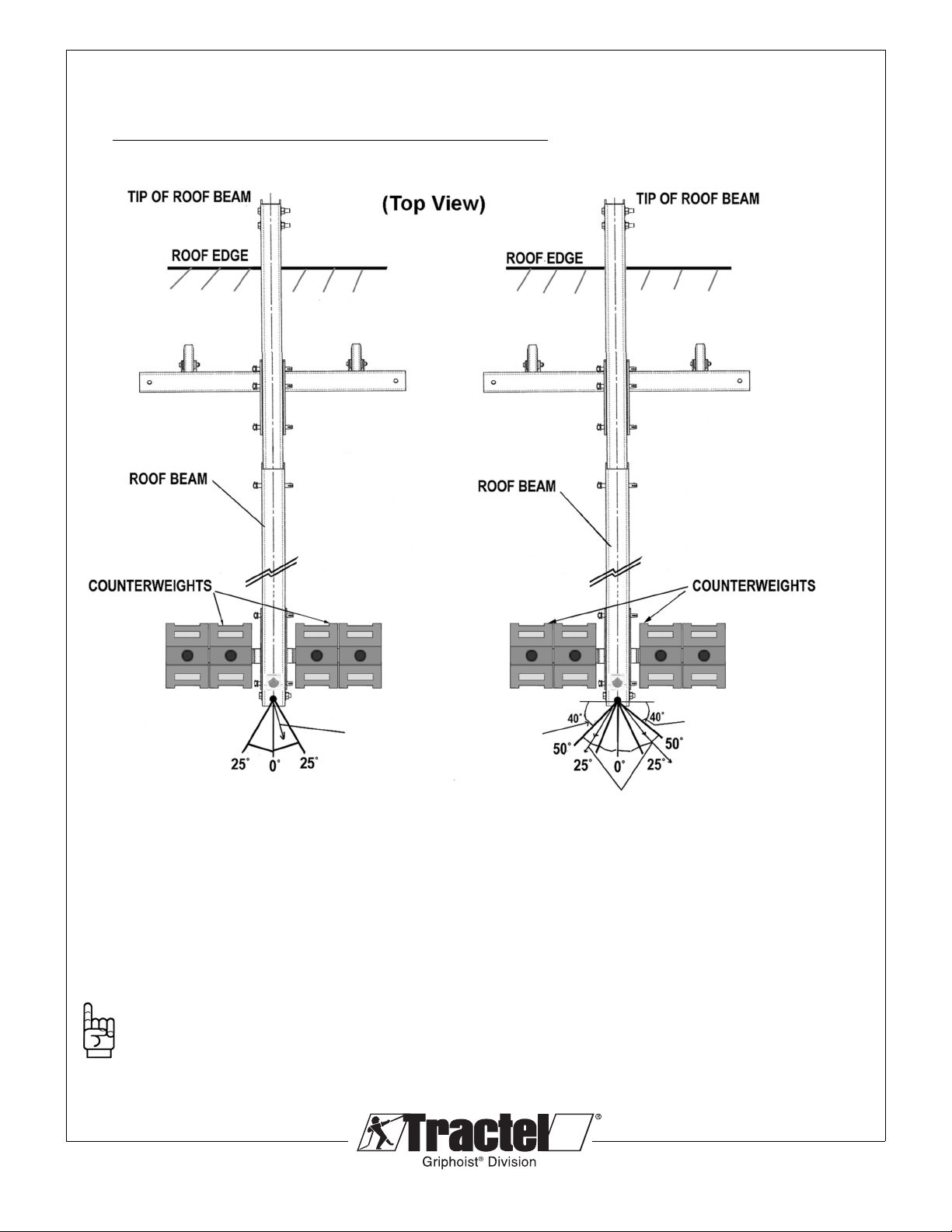
5.1 INSTALLATION OF OUTRIGGER TIEBACKS
Installation of outrigger tiebacks is mandatory!
Fig. 14
Secure tieback to rear shackle on the roof beam, and to the tieback anchor on the roof.
Tieback wire ropes must have the equivalent strength to the hoisting ropes and must be
installed without slack.
NOTE: 1) Tieback may also be installed from the tip of the roof beam.
2) When using the two tiebacks, one must be on each side of the beam.
© 2013 Tractel Ltd. All Rights Reserved.
18
TWO TIEBACKS ARE REQUIRED IF
BETWEEN 25° TO 50° OF CENTERLINE.
ONE MUST BE ON EACH SIDE OF THE
CENTERLINE.
SKYBEAM
SKYBEAM
ONE TIEBACK IS REQUIRED WITHIN
25° OF THE CENTERLINE.
TIEBACK
REQUIRED
TIEBACKS NOT ALLOWED
IN THIS AREA
TIEBACKS NOT
ALLOWED IN
THIS AREA
© 2013 Tractel Ltd. All Rights Reserved.
19
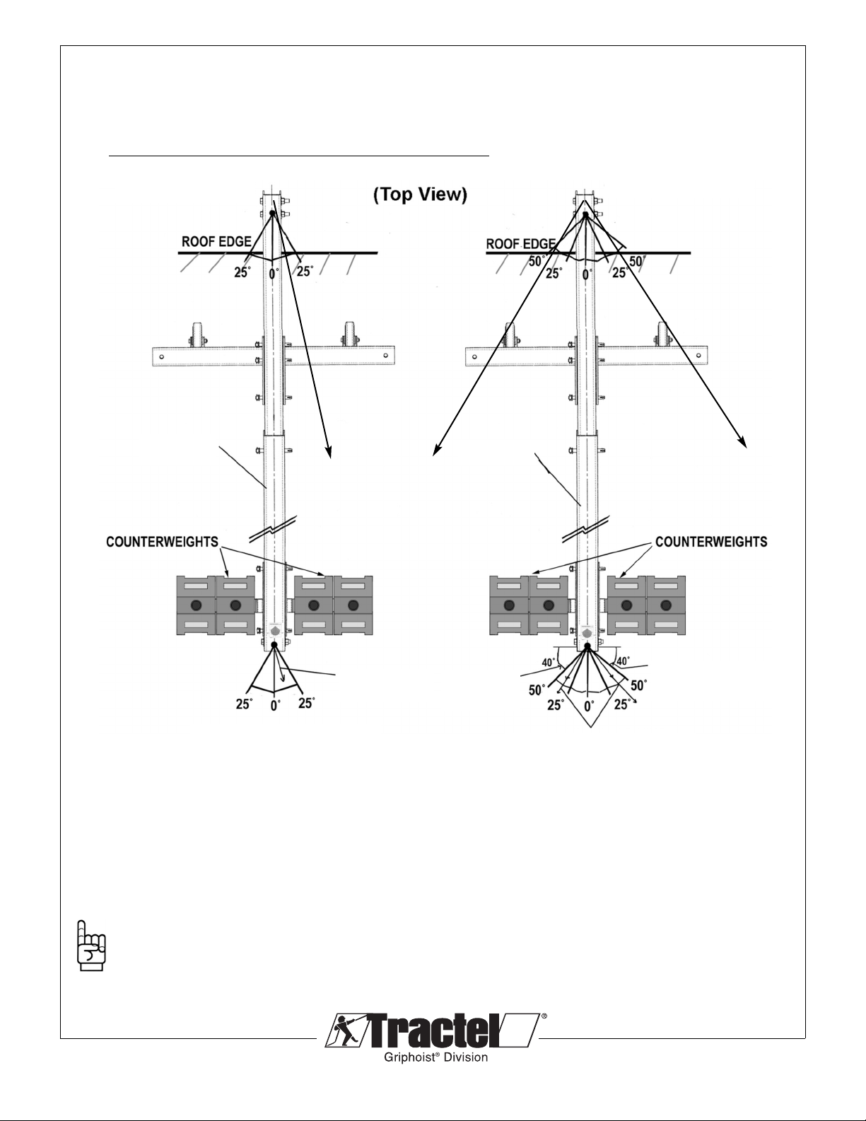
5.1 INSTALLATION OF OUTRIGGER TIEBACKS - CONTINUED
Tieback instructions for the secondary wire rope if installed.
Installation of outrigger tiebacks is mandatory!
Fig. 15
Secure tieback to rear shackle on the roof beam, and to the tieback anchor on the roof.
Tieback wire ropes must have the equivalent strength to the hoisting ropes and must be
installed without slack.
NOTE: 1) Tieback may also be installed from the tip of the roof beam.
2) When using the two tiebacks, one must be on each side of the beam.
Secondary wire rope tieback. Note: only
one required within 25°. Two are
required if between 25° and 50° of the
beam. Tiebacks are not permitted
beyond 50°.
TIEBACK
REQUIRED
TIEBACKS NOT ALLOWED
IN THIS AREA
TIEBACKS NOT
ALLOWED IN
THIS AREA
TWO TIEBACKS ARE REQUIRED IF
BETWEEN 25° TO 50° OF CENTERLINE.
ONE MUST BE ON EACH SIDE OF THE
CENTERLINE.
ONE TIEBACK IS REQUIRED WITHIN
25° OF THE CENTERLINE.
FRONT OF SKYBEAM
SKYBEAM
FRONT OF SKYBEAM
SKYBEAM

Formula for calculating COUNTERWEI HT & LEN TH of
back beam,
(La) 4 (La) 4
W = or b =
b W
W = L x a x 4 ÷ b or b = L x a x 4 ÷ W
W = Counterweight in Pounds
L = Load in Pounds (Rated capacity of oist)
a = Reach (from center front frame to the suspension wire
rope in feet)
b = Back Span - (Distance between front frame and
back frame in feet center to center)
4 = Safety Factor
Severe injury or death can result from improper use or
assembly. Assemble in accordance to this manual. Check
and recheck counterweight chart and formula. Minor
changes could cause complete system failure. Consult your
GRIP OIST dealer for additional information.
Counterweights must be a nonflowable material, and they
must be attached to the outrigger beam.
Always use tieback wire ropes capable of holding the full
load.
© 2013 Tractel Ltd. All Rights Reserved.
20
5.2 CALCULATION OF COUNTERWEIG TS
COUNTERWEIG T FORMULA CALCULATIONS
Provided only as a reference. If you are using the two beam version of the 4’ Skybeam 28 counterweights
are required. The three beam version requires 16 counterweights. Both beams have a 4’ reach and a
1,000lb. (454 kg) Maximum capacity.
Example Calculations:
W= ? L = 1000 lbs.
a = 4 foot b = 11’ 6"
(1000x4) x4
W =
11.5
W = 1391 lbs of Counterweights
(26 pcs.) or more, must be added.
Only have 990 lbs. in Counterweights
then
W= 990 L = 1000 lbs.
a = 4 foot b = ?
(1000x4) x4
b =
990
b = 16’ 2" Therefore the distance
between A and B must be 16 foot and
2 inches or greater.
Table of contents
Other Tractel Lighting Equipment manuals

Popular Lighting Equipment manuals by other brands


ADJ
ADJ ALLEGRO Z6 User instructions

Manaras Opera
Manaras Opera Lightcurtain 003 Specification and installation instructions

EuroLite
EuroLite LED D-40 TCL 2X9W user manual

involight
involight SlimPAR766 user manual

Omron Microscan
Omron Microscan NERLITE Smart Series quick start guide

V-TAC
V-TAC VT-8061 Installation instruction