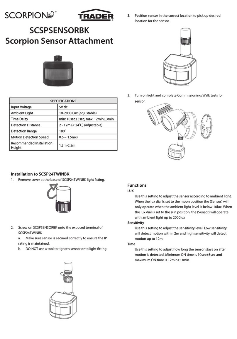
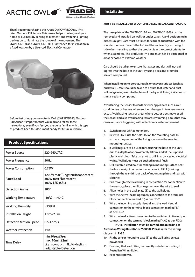
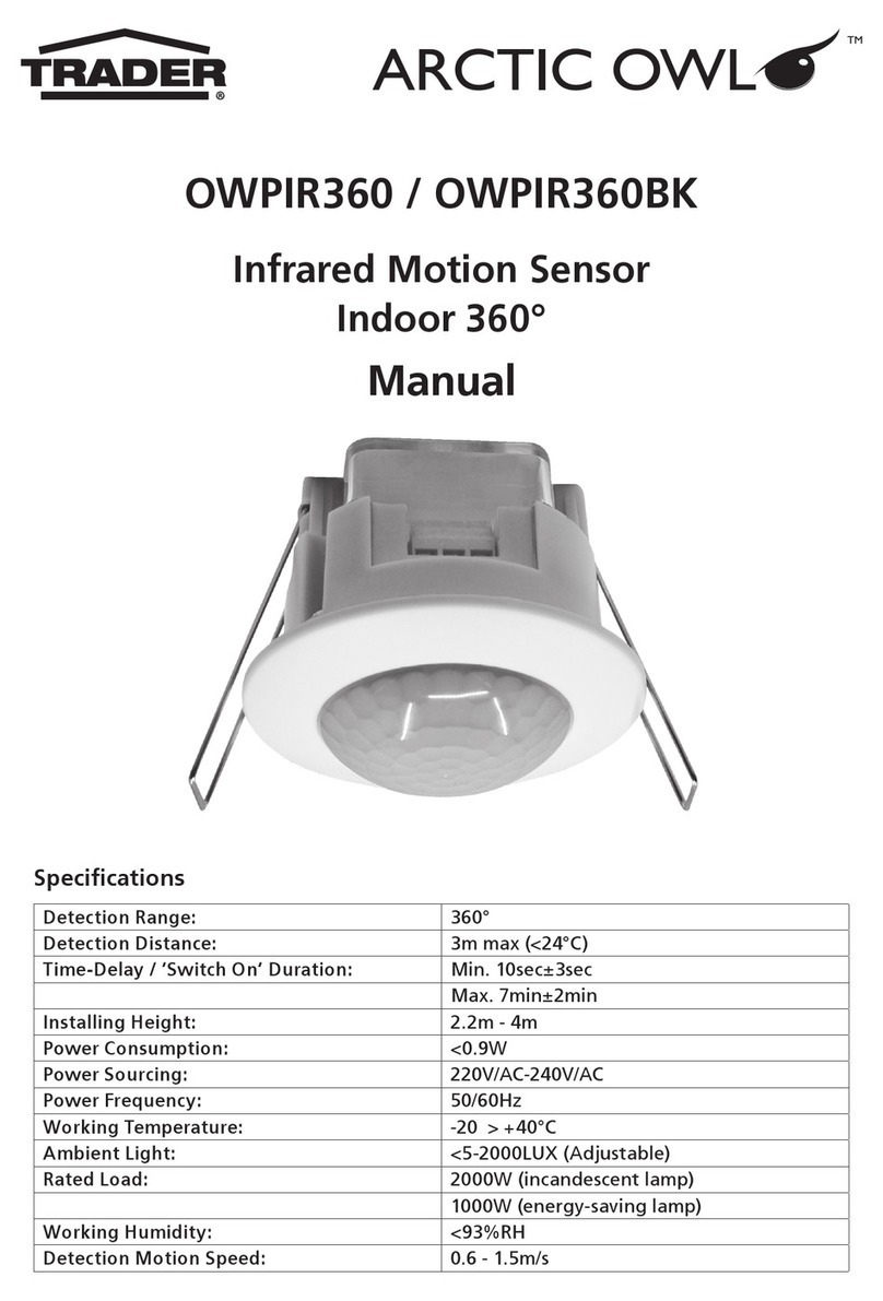
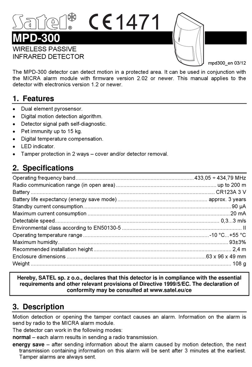
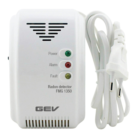
Trader ARCTIC OWL OWPIROD User manual

OWPIROD
Outdoor Infrared Sensor
Specifications
Supply Voltage 220-240V AC 50Hz
Maximum Incandescent Lighting Load 10A 2400W
Maximum Induction Load 5A 1200W
Sensor Power Consumption 0.7W
Detection Method Passive Infrared
Weatherproof Rating IP66
Time Delay 5 to 10 seconds
Warm up to 30 seconds
Detection Angle Up to 110°
Detection Distance Up to 18m

Safety Information
The OWPIROD is a mains connected device and is intended for installation in a fixed location
by a Licensed Electrical Contractor in accordance to applicable Australian wiring rules. The
product must be installed and used in conjunction with detail provided in the enclosed
instructions, failure to do so may cause serious injury. The product contains no user servicable
parts and must be returned to GSM Electrical (Australia) Pty Ltd (GSME) if the product is
damaged and requires repair.
Installation
Before installing your new Arctic Owl (OWPIROD) Outdoor PIR Sensor, it is most important that
you read and follow these instructions, even if you feel you are quite familiar with this type of
product. Keep this document handy for future reference. (If you are the electrical contractor,
please leave the instructions with the client after installation for their future reference).
When operating with standard lighting loads, ensure the lights are pointing away from the
sensor head. Light from the lamps may cause false re-triggering and heat from globes may
harm the sensor unit if too close. The base of the Arctic Owl can be installed in a vertical
manner; such as walls, fascias, or alternatively it may be installed on horizontal surfaces such as
ceilings and under eaves.
When installing onto porous, rough or uneven surfaces (such as brick walls), care should be
taken to ensure that water and dust will not gain ingress into the base of the unit through the
use of a silicon or similar sealant compound. A foam sealing gasket is provided for all other
installation types. It may also be necessary to install the base onto a conduit box or surface
mounting block depending on location.
FIG 1 AB
C
A
E
D
E

Steps for Installation:
1. Switch power OFF at meter box.
2. Refer to FIG 1. Use the holes (A) on the Mounting Base (B) to mark the position of the
fixing screws on the selected mounting surface once the mounting position has been
established.
3. If wall pugs are to be used for securing the base of the unit, drill to a depth of
approximately 40mm, and fit the supplied plastic wall plugs as appropriate. Take care not
to drill into concealed electrical wiring or other services. Wall plugs must be pushed in
until flush.
4. Drill suitable sized hole for cabling in mounting surface between the other two mounting
holes for electrical connections (C).
5. Ensure gasket is positioned over wiring before connecting (D).
6. Pull through electrical wiring in preparation for connection to the sensor.
7. Connect the Active incoming supply connection to the terminal block connection marked
“L’’, as per FIG 2.
8. Wire the incoming supply Neutral and the load Neutral connection to the terminal block
connection marked “N’’, as per FIG 2.
9. Wire the load active connection to the switched Active output connection on the terminal
block marked “S”, as per FIG 2.
NOTE: Installation must be carried out according to Australian Wiring Rules (AS/NZS 3000).
Please refer to the wiring diagram in FIG 3.
10. Remove protective backing from self-adhesive foam gasket (D) as per FIG 1.
11. Attach the self-adhesive foam gasket to the mounting surface or rear of base, aligning
holes in the gasket (E) to the wall plugs as per FIG 1.
12. Fit the sensor mounting base (B) to the wall using screws provided and ensure tightly
secured to maintain IP rating and also tighten adjusting nuts to seal the cable and lock the
head in place.
13. Ensuring that associated lighting loads are correctly installed according to Australian
Wiring Rules.
14. Reconnect power.
FIG 2 FIG 3Removable terminal block

Set Up & Operation
The Arctic Owl OWPIROD Outdoor Sensor is equipped with a highly sensitive PIR (Passive
Infrared) motion detector. A multi-cell technology fresnel lens is used to divide the sensors
basic detection range into multiple separate segments or zones. The sensor automatically
scans for movement between zones, and then will activate connected devices (such as security
lighting) as a result.
The OWPIROD Outdoor Sensor will provide optimal performance and range when installed
in a vertical position approximately 2.5m above the ground; as is shown in the diagrams in
FIG 4 below. The sensor head can be adjusted to allow optimal coverage for the zone of the
detection area by adjusting the head. The horizontal coverage zone can reach up to 18m with
an angle of 110° from the lens.
110°
approx
4m
8m
18m
5°
tilt
4m 8m 18m
2.5m
FIG 4

To adjust sensor head (refer to FIG 5):
Simply loosen the two ball joint locking nuts (A), located at either end of the sensor arm (B),
adjust sensor head (C) and tighten nuts (A).
NOTE: Always loosen locking nuts on sensor before adjusting. Failure to do so can damage the
sensor or crack the lock nut.
Time Duration: The length of time the sensor will activate a light or other load after detection
can be adjusted from 5 seconds to 10 minutes. Rotating the time knob (marked with the clock)
anti-clockwise will reduce the duration time.
LUX Level: The sensor has a built in photoelectric cell that automatically detects daylight
and darkness levels. Rotating the lux control knob anti-clockewise (marked with the day/
night image), will ensure that the sensor only works at night. By rotating the lux control knob
clockwise, the sensor will work in both daylight and at night depending on the application -
this setting is primarily used for testing the sensor after installation.
Sensitivity: The sensitivity control (marked with the sensor symbol) allows you to adjust the
sensitivity of the Infrared detector. This adjustment is useful to adjust the sensitivity of the PIR
to prevent false triggering and to adjust the detection range. Unless required, the sensitivity
adjustment should be operated with the knob turned fully clockwise.
FIG 5
AA
B
C
Time Duration
Lux Level
Sensitivity

Walking the Zone to Commission Installation
1. Rotate the lux knob fully clockwise for daylight operation, set the time control to min
(Anti-clockwise) and the sensitivity to maximum (clockwise).
2. Turn on the power at the isolating switch. The load device should turn on for a short
period of time.
3. Wait 30 seconds for the circuit to stabilise.
4. If not already adjusted, direct the sensor toward the desired area, adjusting the elbow
joint on the sensor arm. Loosen all nuts on sensor before adjusting.
5. Have another person move across the centre of the detection area and slowly adjust the
angle of the sensor arm until the light is switched on. Your sensor is now aimed at your
selected area.
6. Adjust the time control to the desired level.
7. Adjust the sensitivity (if required) to limit detection range. This can be tested via walk
testing.
8. Adjust the lux control by rotating anti-clockwise to revert to night time operation. If the
lights are required to switch on earlier, e.g. dusk; wait for the desired light level, and
slowly turn the lux knob clockwise while someone walks across the centre of the detection
area. When the lights switch on, release the lux control knob.
Manual Override Feature
When the power is initially turned ON, the fitting operates in AUTO mode. In this mode, the
sensor turns the light ON and OFF automatically.
The manual override function means that the fitting can be put permanently “ON”. In this
mode the PIR sensor is disabled.
Resetting the Fitting into “Manual Mode”
9. To bypass the “auto mode” and set the fitting into “manual mode”, turn the wall switch
“OFF” and “ON” once within 3 seconds.
Wall switch action: OFF ON
10. Wait for 3 seconds and the light will turn “ON” permanently and the fitting will be in the
“manual mode”.
Note: If the wall switch action is done more than twice, the fitting may not enter into “manual mode”.
Setting the Fitting into “Auto Mode”
1. To change back to “auto mode”, turn the power “OFF” and wait for about 10 seconds,
then turn it back “ON” again turning the switch “ON” once only.
Wall switch action: OFF, wait 10 seconds ON
2. The PIR sensor will enter into the “Warm-up” mode and the lights will stay “ON” for 10
seconds, then will turn “OFF”.
3. Now wait for about 10 seconds for the circuit to stabilise and the fitting will operate now
in “auto mode”.
Warning: The manual override is linked with the lux setting, and switching on the manual
override will only function at night if the sensor settings are set to functioning in the dark.
It will only work during the day if the lux level is set to daylight.

After Installation & Set Up
To ensure the installation is functioning properly and meets the security/lighting needs, further
adjustments may be required to maintain ideal light level and sensitivity settings.
To ensure a continued high level of performance, ensure the sensor head lens area is regularly
cleaned (3 monthly intervals) from spider webs and dust using a damp cloth.
Troubleshooting
Problem Reason Solution
Unit will not
operate during
daylight.
Sensor not
in daylight
operation mode.
Rotate lux control fully clockwise.
Sensor false
triggering.
Unit may be
suffering from
false activation.
1. Cover sensor unit with a black cloth for a period
of 5 min to check that the light does not trigger.
Occasionally, winds and drafts may activate the sensor.
Sometimes passages between buildings etc. can cause a
“wind tunnel’’ effect.
2. Ensure the unit is not positioned so as to allow
detection of cars/people using public thoroughfares
adjacent to the property. Adjust the sensitivity control
accordingly to decrease range of sensor or adjust
direction of sensor head.
Sensor not
turning off.
Sensor re-
triggering during
operation.
Stand well out of the detection range and wait (the
warm-up period should never exceed 1 minute). Then
check for any extra sources of heat or movement within
the detection area such as animals, trees, light globes
etc. and adjust sensor head and controls accordingly.
PIR will not
operate at
night.
Too much
ambient light.
The level of ambient light in the area may be too bright
to allow operation. Adjust lux level control accordingly
and remove any other sources of ambient light.
PIR sensor will
not operate
at all.
No power.
Check that the power is switched ON at the circuit-
breaker or internal wall switch. Ensure that connections
are not loose.
Unit activates
during the
daytime.
Low level of
ambient light or
lux level control
set incorrectly.
The level of ambient light in the area may be too dark
to allow operation in night time only mode. Re-adjust
the lux control accordingly.

5 Year Manufacturer’s Warranty
This product has been manufactured to the highest quality standards.
This product is warranted to the original purchaser and is not transferable.
The product is guaranteed to be free from defects in workmanship and parts for a period of 5
Years from the date of purchase. Defects that occur within this warranty period, under normal
use and care will be repaired, replaced or refunded. The benefits conferred by this warranty
are in addition to all other rights and remedies of the consumer under Commonwealth,
State and Territory laws in relation to the goods or services to which this warranty relates
and Australian Consumer Law. Risk in regard to the product to be repaired shall at all times
remain with the Purchaser. The warranty is given on the condition that the product to which it
applies is used for the purpose and in the manner intended by its construction and for no other
purposes whatsoever. GSM Electrical (Australia) Pty Ltd shall not be responsible for damage
of any kind, caused by accidents, power surges, electrical storm damage, incorrect power
current, infestation (vermin or insect), incorrect installation, incorrect electricity or plumbing
installation, improper use of controls or failure to use the product in accordance with the
operating instructions, general misuse or abuse or from normal wear and tear. Any attempt by
an unauthorised person to repair or tamper with the equipment shall render the warranty null
and void.
GSM Electrical (Australia) Pty Ltd’s liability under this warranty is limited to the replacement
and/or repair of the defective parts within the warranty period and does not extend to
installation or removal of the product. Acceptance of liability by GSM Electrical (Australia) Pty
Ltd contained herein is to the exclusion of any other remedy whatsoever and howsoever arising
in respect of any equipment to which it applies.
GSM Electrical (Australia) Pty Ltd
Level 2 142-144 Fullarton Road
Rose Park SA 5067
www.gsme.com.au
Phone: 1300 301 838
Fax: 1300 301 778
Table of contents
Other Trader Security Sensor manuals
