ENGLISH FRANÇAIS DEUTSCH ITALIANO ESPAÑOL PORTUGUÊS
EN-5
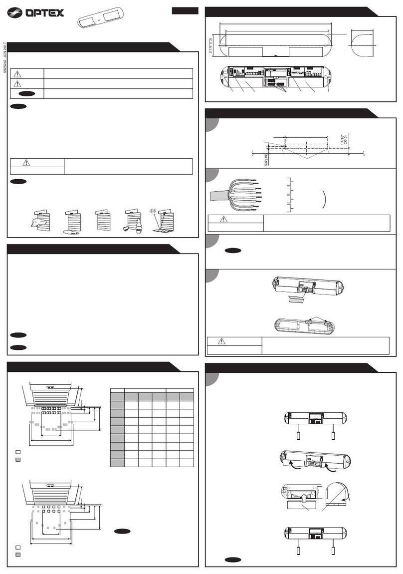
4Tilt the bracket about 45° and pass
through the wire.
In Out
5
6Open the wiring knockout.
To the right To the left
Wiring knockout
Determine the horizontal direction (left or right) of
the detector before installing the bracket on the wall.
7
Knockout with 4 × 20 tapping screw (screwkit)
Open the Up-Down lock screw knockout for
connecting the bracket.
8
Wiring
hole
Wiring
sponge pad
In
Tighten screws 1 and 2 , adjust the bracket angle
(refer to 2-2), then tighten screw 3 .
Perform an area check. If re-adjustment is required,
loosen screw 3 and change the bracket angle.
After the adjustment is complete, tighten screw 3
again.
Out
14 × 20
screw
34 × 35
Up-Down
lock screw
2
4 × 20
screw
Adjustment
screw
9Tighten the adjustment screw clockwise.
10 Wire to the terminal and install the main unit and
lens on the base. 11 Install the shaft cover into place.
12 m (40 ft.)
3.0 m (10 ft.)
0° is the right setting for 3.0 m
(10 ft.) height installation.
Adjust 1 click (2.5° upward) for 2.5 m
(8.2 ft.) height installation.
4 clicks (10°)
2 clicks (5°)
0°
Example (the ground is level)
* This is the case to have 12 m
detection length.
Perform the walk test to check
if detector is parallel to the ground.
For best performance, install detector parallel to the ground.
Decide the detection length. If you choose 9.0 m/5.5 m/4.0 m, mask the unnecessary lens with masking seals.
Caution>>
If the base of the unit is already
parallel to the ground,
• Do not change the detection
length by tilting the unit up or
down. Detection length should
be adjusted with masking
seal. Refer to 2-1 for the
details.
If the detection length is shorter
than the designated one (refer to
page 3), change the detector
angle upward. If the detection length is equal to the
designated one, adjustments have
been completed.
If the detection length is longer
than the designated one (refer to
page 3), change the detector
angle downward.
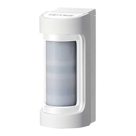
1Open the wiring knockout with suitable tool
e.g. screwdriver.
3Fasten the base to the wall.
2Pull the wire through the base knockout.
4Install main unit after wiring to the terminal.
In
Out
Wiring sponge pad
2-2
ADJUSTING THE VERTICAL ANGLE
2-3
MOUNTING WITHOUT THE BRACKET
